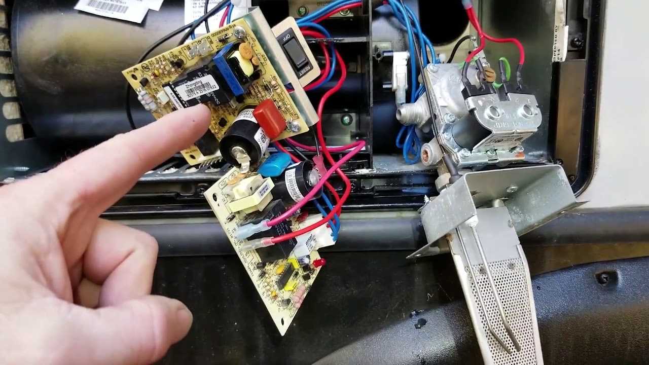
The inner workings of certain heating units can often appear complex, but a closer look reveals a logical arrangement designed for efficient heat production. Each element plays a critical role in ensuring a smooth operation, and their collective arrangement is crucial for the unit’s overall efficiency and safety. By exploring these configurations, users can better understand how warmth is generated and distributed.
Within this setup, various mechanisms collaborate to transform energy into warmth, regulate temperature, and maintain airflow. Identifying and understanding these elements can aid in troubleshooting, maintenance, and upgrades, making it easier for owners and technicians to maintain optimal performance. A clear view of the structure helps pinpoint potential issues and ensures effective operation for years to come.
Recognizing the significance of each component and its precise positioning allows for a deeper appreciation of the unit’s design. This knowledge empowers users, whether they are seeking to replace a specific part or simply wish to grasp how each element contributes to the overall function. The details provided in the following sections offer insights into the specific arrangements, guiding both enthusiasts and professionals through the intricacies of this heating solution.
Overview of Hydro Flame Furnace Components
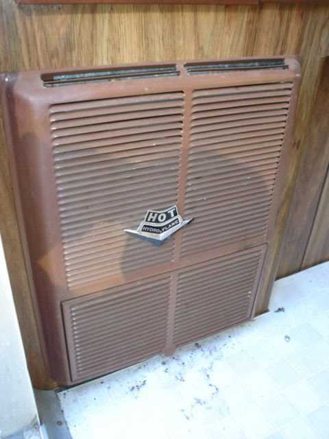
The system in question is designed to efficiently produce heat, incorporating various elements that work together to ensure warmth and comfort. Each element has a specific function, contributing to the overall process of temperature regulation and air circulation. Understanding these elements can help in identifying potential issues and maintaining effective operation.
Primary Heating Element
The core heating unit serves as the main source of warmth, converting energy into thermal output. This part is crucial as it generates the required heat, which is then distributed throughout the space. Built for durability and efficiency, the heating unit plays a key role in maintaining a consistent internal environment.
Air Distribution Mechanism
For optimal heat flow, the air distribution setup channels warmed air into different areas. A motorized fan is typically responsible for circulating air, ensuring even temperature levels. Proper functioning of this mechanism is vital for balanced heating, as it helps avoid hot or cold spots.
Safety Features like automatic shut-off valves and sensors are integrated to prevent overheating or gas leaks, enhancing the reliability and security of the system. These components ensure the equipment operates safely, providing peace of mind for users
Key Elements in Heating Mechanism
The process of generating warmth relies on a combination of interconnected components working seamlessly. These elements collaborate to ensure efficient heat production, safe operation, and consistent distribution throughout the space. Understanding the primary components helps to identify how each part contributes to the overall thermal process.
- Combustion Chamber: The core space where the conversion of energy takes place, releasing warmth as fuel is ignited and burned efficiently.
- Ignition System: Responsible for initiating the thermal cycle, this element ensures that the energy source is properly triggered to start the heating process.
- Heat Exchanger: Transfers the generated warmth to the surrounding air or medium. It maximizes energy usage while keeping combustion gases isolated from the air being warmed.
- Blower Fan: This component circulates air through the system, pushing warm air into the designated area and helping to maintain even temperature levels.
- Safety Sensors: These critical devices monitor temperature and other factors to prevent overheating, ensuring that the system runs safely and effectively.
Together, these elements form an integrated process, transforming energy into a steady source of comfort. Each component plays a specific role, contributing to an efficient and secure system.
Common Issues with Internal Parts
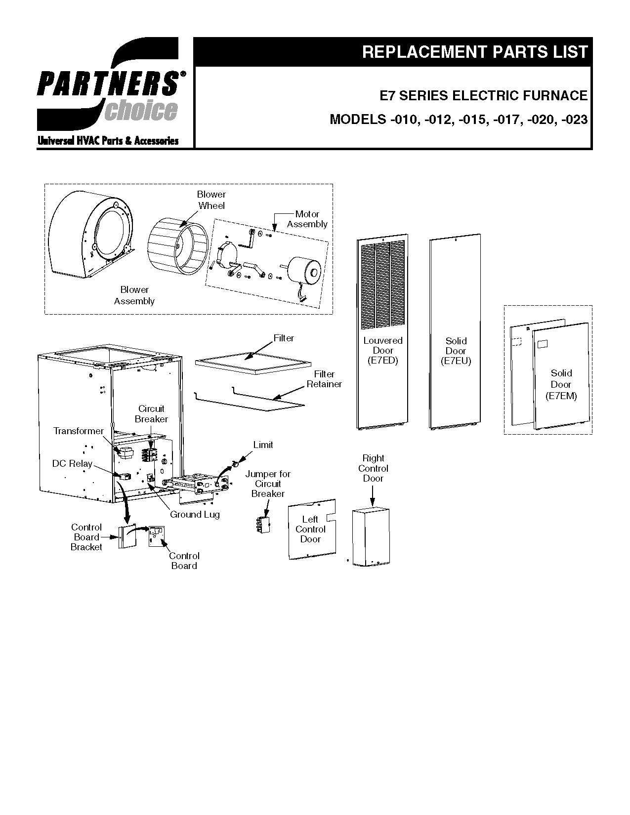
Understanding the potential challenges that can arise within the core components of these heating units is crucial for maintaining their efficiency. Various elements inside the unit can experience wear over time, leading to decreased performance or even failures. Addressing these concerns early can help prevent more significant problems down the line.
Temperature Regulation Problems
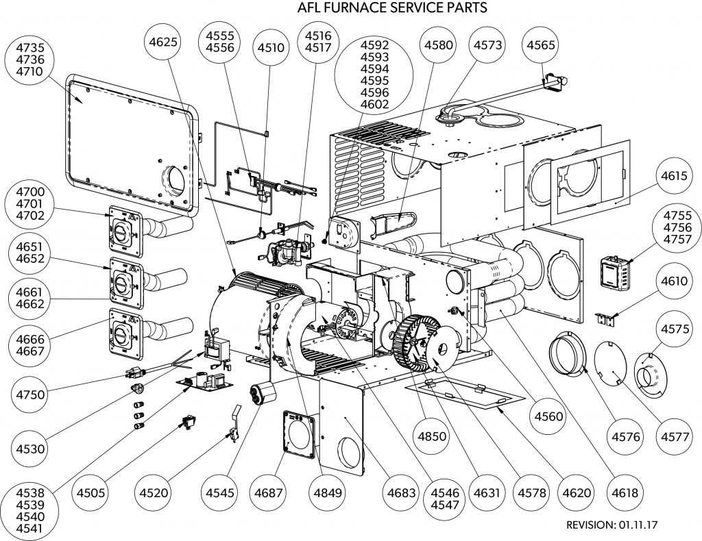
One frequent issue involves inconsistencies in heat control. If the temperature fluctuates unexpectedly, it may indicate malfunctioning sensors or a compromised control board. These components are responsible for managing the heat output, and any faults in them can result in uneven warming or sudden shut-offs.
Airflow Blockages
Another common challenge is related to restricted circulation. Dust, debris, or obstructions can accumulate in the ventilation channels, causing inadequate air movement. This can lead to overheating or reduced warmth distribution. Regular maintenance and cleaning of these passages can mitigate such concerns, ensuring
Understanding the Control Board Function
The central module plays a pivotal role in managing the entire system’s operations. It acts as the brain of the mechanism, coordinating various inputs and outputs to ensure seamless functionality. This component processes signals, adjusts settings, and maintains safety protocols, contributing to optimal performance and user comfort.
Main Responsibilities of the Central Module
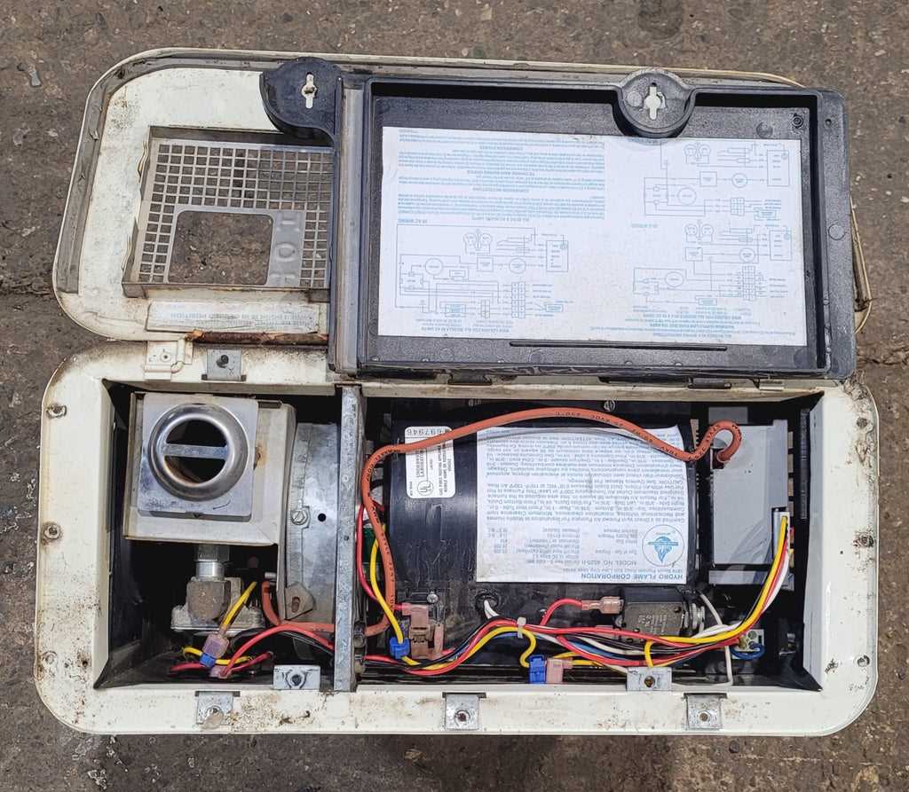
- Regulating Temperature: The unit continuously monitors thermal levels, ensuring that the environment reaches and maintains the desired settings.
- Managing Power Flow: It controls the distribution of electrical current to different elements, balancing power needs while preventing overloads.
- Safety Protocols: Integrated safety measures detect irregularities, automatically adjusting or halting operations to avoid potential hazards.
Key Inputs and Outputs
This module interacts with various components, receiving data from sensors and relaying instructions to actuators. Key elements include:
- Temperature Sensors: Detect fluctuations and send data to adjust the system’s operations accordingly.
- Ignition Signals: Manage the activation and deactivation of core functions based on user input and pre-set parameters.
- Status Indicators: Provide visual feedback for operational status, ensuring users are informed of the system’s condition.Maintenance Tips for Longer Lifespan
Regular upkeep can significantly extend the service life of heating systems. A consistent routine helps to ensure that all components operate efficiently, reducing the risk of unexpected malfunctions. Following a few essential practices can keep the system running smoothly and minimize the need for costly repairs.
Regular Cleaning and Inspection
Dust and debris can accumulate in various sections of the unit, affecting performance. Periodic cleaning of vents, filters, and surrounding areas prevents blockages that can restrict airflow. Regular inspections help in identifying early signs of wear and potential issues before they escalate.
Component Checks and Replacements
Over time, certain elements of the unit may wear out due to regular use. Checking connections, switches, and safety mechanisms can prevent larger problems. Replace worn-out components promptly to maintain efficiency and safety. Maintaining a record of these checks can help track the health of the system.
Maintenance Task Recommended Frequency Clean Vents and Filters Every 3 Months Inspect Safety Mechanisms Annually Replacement Parts for Different Models
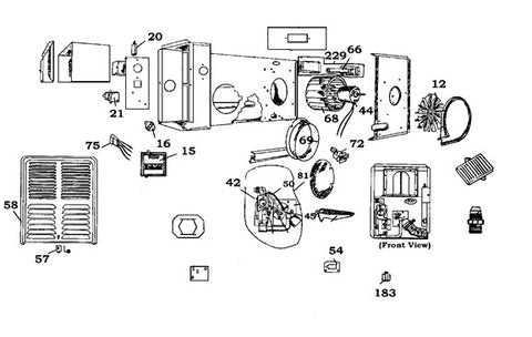
When dealing with various heating systems, it is essential to understand the significance of compatible components. Each model may have specific requirements, leading to variations in the types of elements that can be utilized. This section outlines the considerations for selecting appropriate substitutes based on individual system specifications, ensuring optimal performance and longevity.
Understanding Compatibility
Compatibility is critical when selecting replacement components. Different models may utilize unique configurations or specifications that must be matched for efficient operation. Familiarizing oneself with the characteristics of each unit will aid in identifying the right alternatives, minimizing installation challenges and ensuring seamless integration.
Common Replacement Components
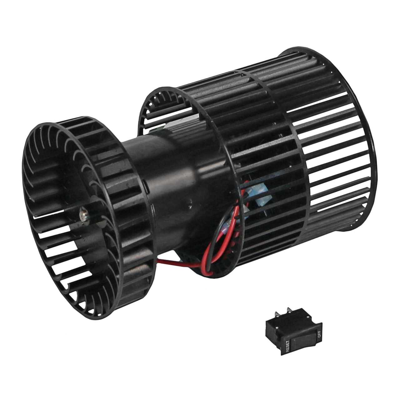
Several components are frequently replaced due to wear or malfunction. These may include igniters, blowers, and control boards, each playing a vital role in the system’s functionality. Knowing the typical replacements for specific models allows for quicker repairs and reduced downtime, enhancing the overall reliability of the heating solution.
Troubleshooting Common Electrical Problems
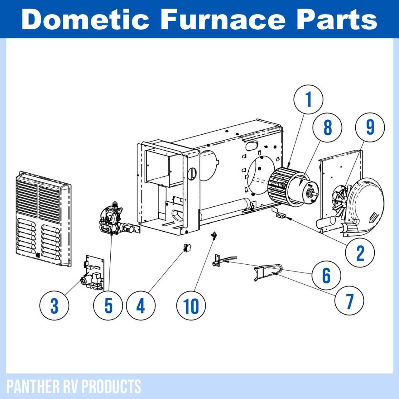
Identifying and resolving electrical issues can be a challenging task, especially when dealing with heating systems. Understanding the common electrical failures and their symptoms can help users restore functionality quickly and efficiently. This section outlines key troubleshooting strategies to address frequent electrical malfunctions.
Identifying Power Issues
Power interruptions can arise from various sources, including blown fuses or tripped circuit breakers. Inspecting the main power supply is the first step in diagnosing these problems. Ensure all connections are secure and that the appropriate voltage is being supplied. If the system does not respond, it may be necessary to check for damaged wires or connectors.
Addressing Control Malfunctions
Control components are essential for the proper operation of heating systems. Faulty thermostats or control boards can lead to erratic behavior or complete system failure. Testing these components with a multimeter can help verify their functionality. If any irregularities are found, replacing the defective part may be necessary to restore normal operation.
How to Identify Faulty Components
Recognizing malfunctioning elements within a heating system is essential for maintaining efficiency and safety. Understanding common indicators of issues can prevent further damage and ensure optimal performance. Below are some effective methods to diagnose problematic components.
Visual Inspection
Begin by conducting a thorough visual assessment. Look for signs of wear, corrosion, or physical damage. Any discoloration or unusual deposits may signal a problem. Pay close attention to connections, ensuring they are secure and free from debris. A clean, well-maintained appearance often correlates with proper functioning.
Performance Testing
Next, assess the system’s overall functionality. If the heating cycle is irregular or the output is insufficient, it may indicate a malfunction. Utilize testing tools to measure voltage and current in critical areas. Deviations from the expected ranges can help pinpoint faulty components, allowing for targeted repairs.
Upgrading for Better Heating Efficiency
Enhancing the performance of your heating system can lead to significant improvements in energy consumption and comfort levels. By investing in modern technologies and components, you can optimize your setup for maximum efficiency.
Consider the following upgrades:
- High-Efficiency Burners: Replacing older burners with high-efficiency models can significantly reduce fuel usage while increasing heat output.
- Advanced Thermostats: Installing smart thermostats allows for better temperature control and can adjust heating patterns based on your schedule.
- Insulation Improvements: Enhancing insulation in ducts and around your unit minimizes heat loss, ensuring that more warmth reaches your living spaces.
- Variable Speed Blowers: Upgrading to variable speed fans enables more precise air distribution, resulting in improved comfort and reduced energy use.
- Regular Maintenance: Committing to regular inspections and tune-ups can help identify inefficiencies and keep your system running smoothly.
Implementing these enhancements not only promotes a more comfortable environment but also contributes to long-term savings on energy costs.