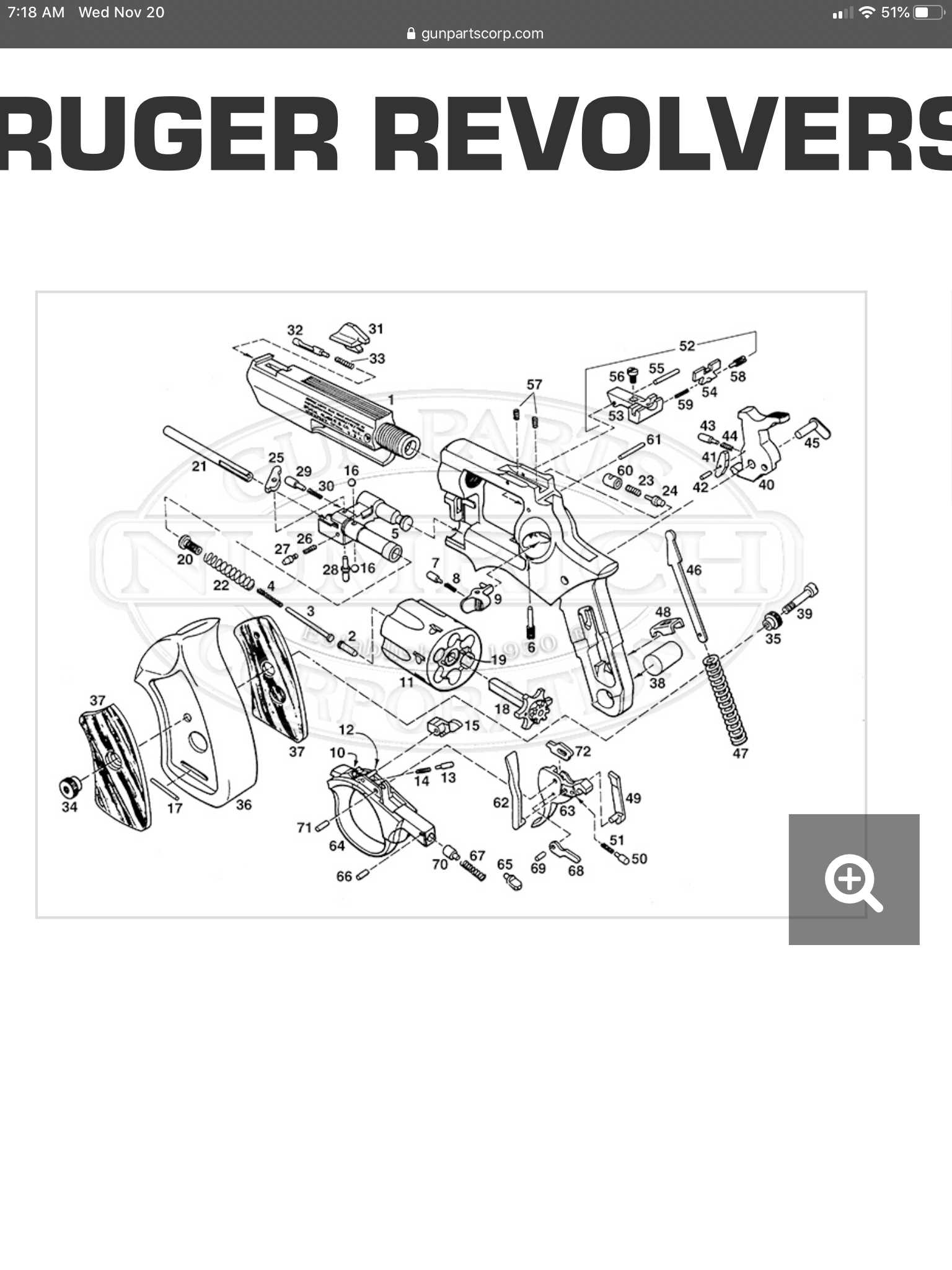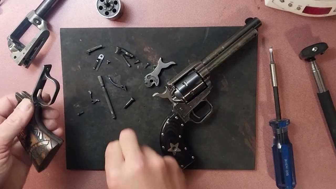
When it comes to maintaining or upgrading your firearm, understanding its individual components and how they function together is crucial. Each element has a unique role in ensuring the performance, safety, and durability of the weapon. Proper knowledge of the structure allows for more effective repairs, customization, and routine checks, ensuring that everything operates smoothly.
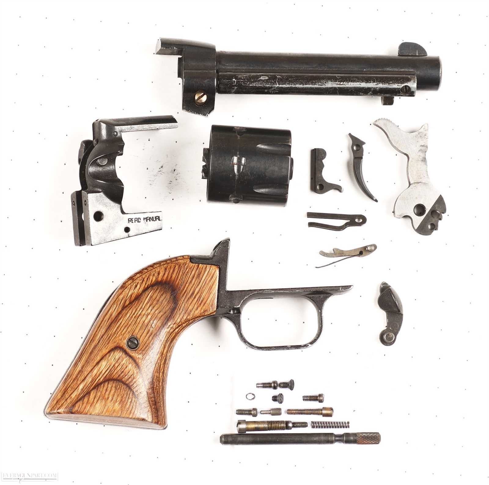
In this section, we will dive deep into the various mechanisms that make up this well-known firearm. By examining each part closely, you will gain insight into its purpose and functionality, which can be particularly beneficial for enthusiasts looking to optimize or modify their equipment. This breakdown will provide valuable guidance for anyone aiming to improve their understanding of
Understanding the Function of Key Components
In this section, we explore the primary elements that ensure the smooth operation of a classic single-action system. Each component plays a significant role in the overall performance and reliability of the firearm. Understanding how these elements interact is crucial for both maintenance and effective use.
Trigger and Hammer Mechanism
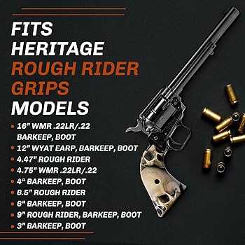
The trigger and hammer are responsible for initiating the firing process. When the trigger is pulled, it releases the hammer, which strikes the firing pin to ignite the ammunition. The smooth coordination between these two components ensures precise control over the firearm’s discharge.
Cylinder and Barrel Alignment
The cylinder holds the ammunition and rotates with each cock of the hammer, aligning the next round with the barrel. Proper synchronizati
Barrel Assembly Overview and Maintenance Tips
The barrel assembly plays a crucial role in the performance and accuracy of any firearm. Proper understanding of its structure and regular upkeep are essential for ensuring reliable operation and long-term durability. This section provides an overview of the key elements of the barrel system, along with practical advice on how to maintain it effectively.
Key Components of the Barrel Assembly
The barrel assembly is comprised of various components that work together to direct and stabilize the projectile. These elements typically include the barrel itself, which is responsible for the bullet’s trajectory, and other associated parts that assist in securing and supporting its operation. Understanding the interaction of these components is important for troubleshooting and performance optimization.
Maintenance Tips for Longevity
To maintain the longevity of the barrel assembly, regular cleaning and inspection are necessary. U
Exploring the Internal Mechanism Layout
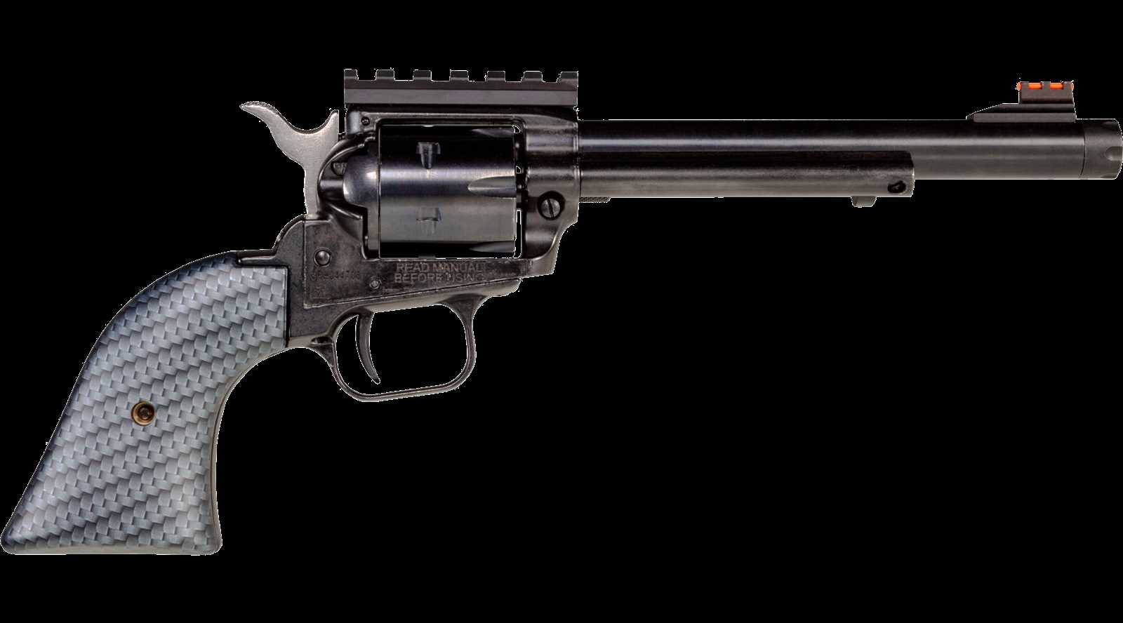
The internal structure of this revolver is a carefully designed system that ensures smooth and reliable operation. Understanding how the components interact is essential for maintenance, customization, or repair. Each element plays a specific role in transferring motion and controlling the firing sequence.
Trigger and Hammer Interaction: The relationship between the trigger and hammer is crucial for the firing process. When the trigger is pulled, it releases the hammer, which strikes the firing pin, igniting the round. This motion must be finely tuned to avoid misfires or excessive wear.
Locking and Safety Mechanisms: The revolver incorporates a series of locking devices to ensure safety. These mechanisms prevent accidental discharges and ensure that the firearm remains secure when not in use. They engage and disengage with each action of the cylinder and hammer.
Cylinder Rotation System: A
Trigger Group Breakdown and Its Role
The trigger group plays a pivotal role in the overall functionality of a firearm. This assembly ensures the controlled and reliable release of the hammer, influencing the firearm’s responsiveness and precision. Understanding its components and how they work together can help with maintenance and troubleshooting, leading to more effective and safe use.
Key Components of the Trigger Assembly
The trigger mechanism consists of several interconnected elements, each performing a crucial task in the firing process. These include the trigger itself, the sear, and the hammer. Their interaction determines how smoothly and consistently the firearm discharges, and minor malfunctions in this system can significantly affect performance.
| Component | Function |
|---|---|
| Trigger | Initiates the
Hammer and Firing Pin Configuration Explained
The interaction between the hammer and the firing pin plays a crucial role in the mechanical operation of a firearm. Understanding how these components work together is key to ensuring reliability and safety during use. This section explores the key features of this mechanism, outlining the fundamental processes involved in striking the cartridge and discharging a round. Hammer MechanicsThe hammer is a pivotal element, responsible for transferring kinetic energy to the firing pin. When the trigger is pulled, the hammer moves swiftly forward, powered by tension from a spring mechanism. This motion enables it to strike the firing pin with precision, initiating the firing sequence. Proper alignment and tension within this system are essential for consistent performance. Firing Pin Function
Once the hammer impacts the firing pin, the pin drives forward to strike the cartridge primer. This causes a small explosion, igniting the gunpowder and propelling the bullet forward. The firing pin’s length and shape must be carefully calibrated to avoid misfires or accidental discharges, highlighting the importance of met Disassembling and Reassembling the Cylinder AssemblyUnderstanding how to take apart and put together the cylinder assembly is crucial for maintenance and repair. This process ensures the proper functioning of the mechanism, allowing for smoother operation and increased longevity. Below is a step-by-step guide to help you through the process efficiently. Tools Required
Steps to Disassemble the Cylinder
|
