When working with a multi-port valve, it’s essential to recognize the core elements that make up its structure. These components are intricately designed to work together, ensuring optimal control over water flow and system efficiency. By becoming familiar with these elements, maintenance and troubleshooting become more straightforward, reducing the need for extensive repairs.
The valve is composed of several critical units that each play a unique role in regulating pressure and directing the flow of liquid through the system. Knowing how these pieces function and interact with each other can extend the life of the device and enhance performance.
Whether you’re replacing worn elements or conducting routine inspections, understanding the internal layout is crucial. This allows for more effective servicing and helps maintain the system’s reliability over time.
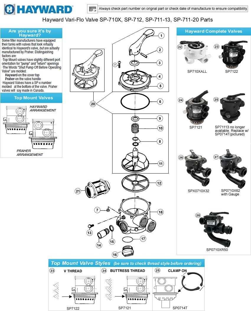
Overview of Key Components in the Hayward SP710XR50
The system features a variety of critical elements, each working together to ensure efficient operation. Understanding these components helps in the overall maintenance and functionality of the equipment, as each part plays a vital role in regulating flow and control.
Main Control Mechanism
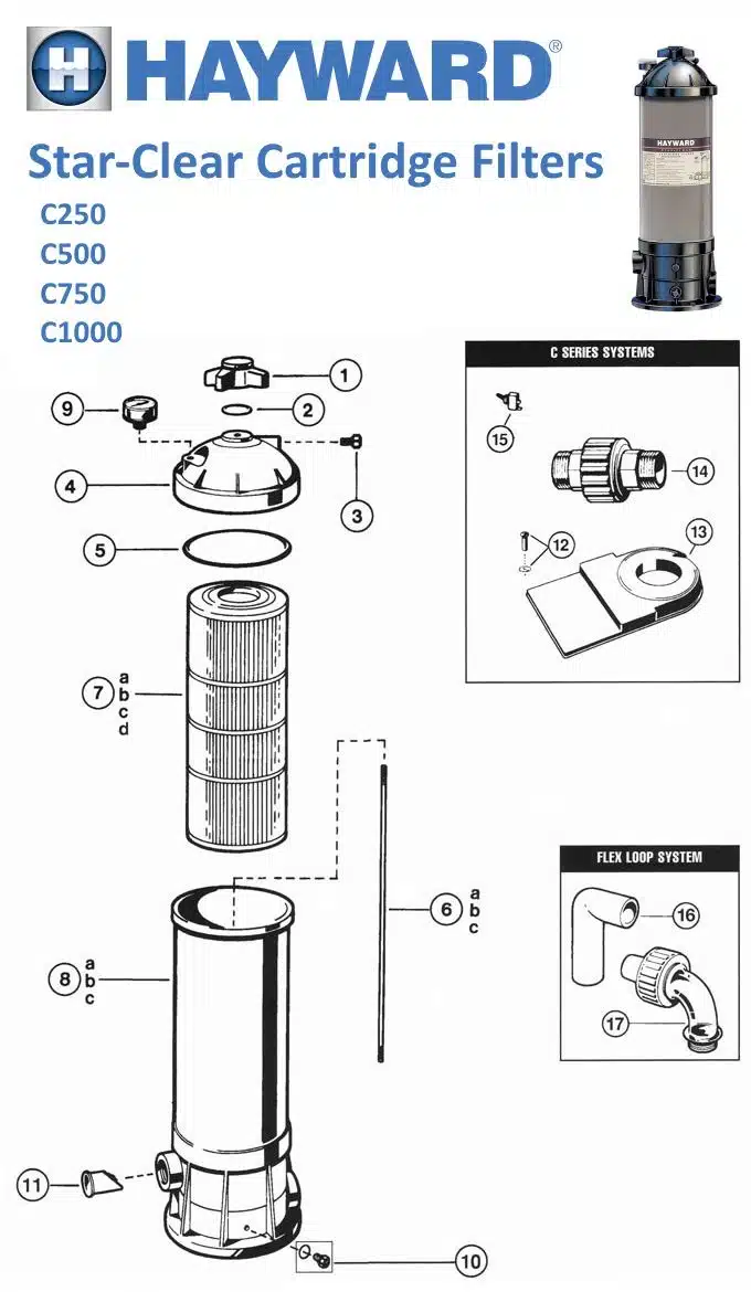
This section is responsible for directing the water flow through different pathways. It allows precise adjustments, ensuring proper circulation and filtration. With its intuitive design, the control mechanism provides smooth operation, minimizing the chances of leaks or inefficiencies.
Seals and Connectors
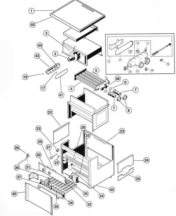
Seals and connectors are essential for maintaining the integrity of the system. They prevent unwanted leaks and ensure that connections between various elements are secure. Regular inspection of these parts can prevent wear and extend the lifespan of the overall assembly.
Detailed Breakdown of Valve Structure
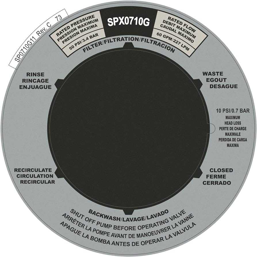
The intricate design of the valve’s inner mechanisms ensures smooth and efficient operation across various settings. Understanding the components that comprise the unit helps in identifying how the flow control is managed, directing the liquid with precision and preventing potential leaks or inefficiencies.
Key Internal Components
Inside the valve, there are several critical elements that work together to regulate the flow. The primary unit responsible for control is the rotary handle, which adjusts the direction of movement. Beneath it, seals and gaskets play a vital role in maintaining pressure while preventing any unwanted discharge.
Flow Control System
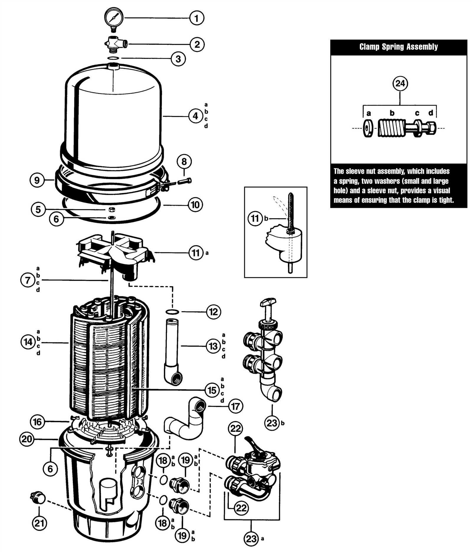
At the core of the valve is the flow diverter, a mechanism that shifts the direction of water based on the selected setting. This is supported by a system of channels and ports, ensuring that the pressure remains consistent while allowing users to modify the flow without resistance.
Identifying Commonly Replaced Parts
Understanding the most commonly exchanged components in any system is crucial for ensuring smooth operation and extending its lifespan. When wear and tear take their toll, certain elements often need more frequent attention and replacement to keep the equipment functioning efficiently.
Wear and Tear: High-Impact Components
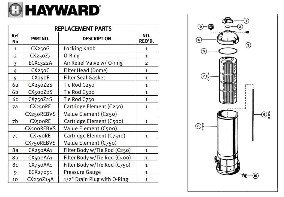
Among the most frequently swapped components are those subjected to constant friction or pressure. These elements endure the highest levels of strain and are typically the first to show signs of deterioration. Regular inspection and timely replacement of these can prevent major malfunctions.
Maintenance Checklist: What to Monitor
For optimal performance, specific parts should be checked during routine maintenance. This can help you avoid unexpected breakdowns and costly repairs. Below is a table listing common elements that often require inspection or replacement:
| Component | Frequency of Replacement | Signs of Wear | ||||||
|---|---|---|---|---|---|---|---|---|
| Seals and Gaskets | Annually | Leaks, Cracks, Discoloration | ||||||
| O-Rings |
| Pressure Range | Action Required |
|---|---|
| Too Low | Check for leaks or system blockages. |
| Too High | Inspect for overpressure or faulty valves. |
| Normal | System is operating correctly. |
By maintaining regular checks on the pressure readings, you ensure that the system remains in optimal condition, reducing wear and extending the lifespan of the components.
Proper Lubrication of Moving Parts
Ensuring the longevity and smooth operation of mechanical systems requires proper attention to lubrication. When moving components interact, friction can lead to wear and tear, reducing efficiency and potentially causing damage. Adequate lubrication not only minimizes this friction but also helps in maintaining the overall health of the machinery over time.
Choosing the Right Lubricant
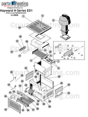
Different systems require specific types of lubricants. It is essential to select a lubricant that matches the operational environment, load conditions, and temperature ranges. The wrong choice can result in poor performance or even premature failure of the components.
- Viscosity: Select a lubricant with appropriate thickness for the system’s speed and load.
- Temperature resistance: Ensure the lubricant can withstand the operating temperatures.
- Compatibility: Ensure it works well with the materials used in the system.
Application Techniques
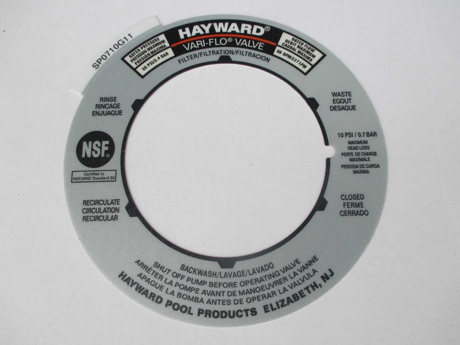
Applying lubrication correctly is crucial to maximize its benefits. Too little lubrication may fail to reduce friction, while too much can attract dirt and debris, which could cause blockages or other issues.
- Use the manufacturer-recommended application methods to ensure even distribution.
- Apply lubricant at regular intervals to maintain consistent performance.
- Check for any signs of leakage or contamination after application.
Tips for Maintaining Longevity of Parts
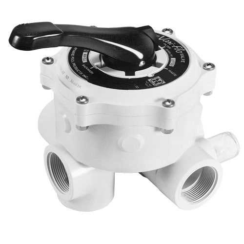
Proper care and regular upkeep are essential to ensure the extended life of components within your equipment. By following simple yet effective maintenance practices, you can prevent premature wear and reduce the likelihood of costly replacements. Regular checks, cleaning, and correct usage are key to ensuring optimal performance over time.
1. Regular Inspections: Conducting routine inspections will help you identify early signs of wear or damage. This allows you to address potential issues before they escalate, preventing more significant damage to other elements of the system.
2. Clean Thoroughly: Ensure that all components are free from dirt, debris, or any other foreign materials that could interfere with their function. Periodic cleaning helps in maintaining smooth operation and extends the service life of the system.
3. Avoid Overuse: While it’s tempting to push equipment to its limits, excessive strain can lead to faster deterioration. Follow manufacturer guidelines for optimal usage, and avoid continuous operation without necessary breaks.
4. Use Proper Lubrication: For moving parts, applying the right type of lubricant will reduce friction and wear. Ensure you are using the recommended lubricant and apply it in the correct manner to prevent buildup or damage.
5. Store Properly: When not in use, store components in a dry, cool area to prevent damage from environmental factors such as moisture or excessive heat. Proper storage conditions ensure that parts retain their integrity and functionality.
Replacement Options for Obsolete Components
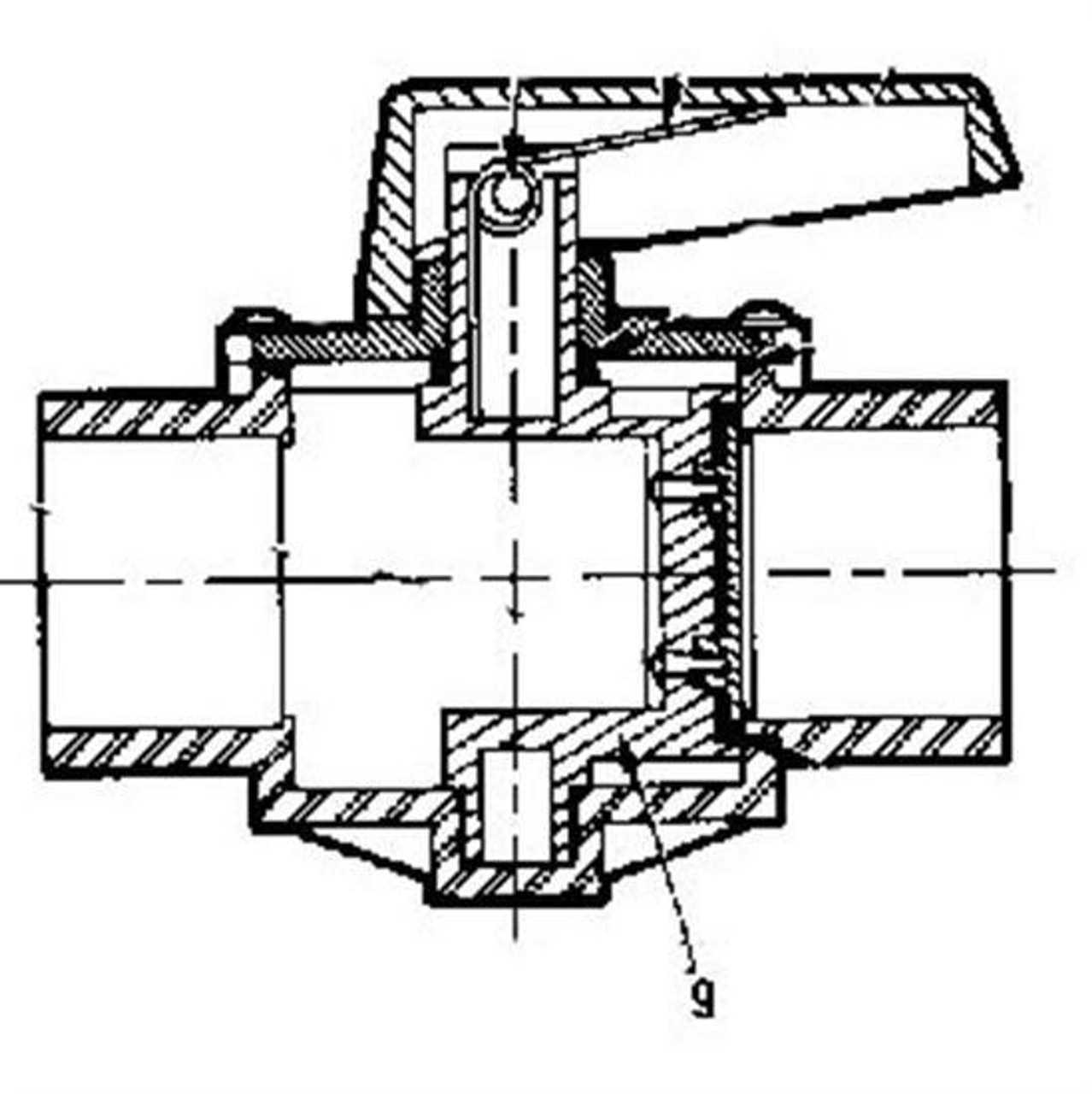
When certain components reach the end of their service life, finding suitable alternatives becomes essential to maintain system performance and reliability. Often, these components may no longer be in production, but that doesn’t mean replacements aren’t available. Identifying compatible parts and ensuring they meet operational standards is critical for continued functionality.
Several factors should be considered when seeking alternatives:
- Compatibility: Ensure the replacement fits seamlessly with the existing setup.
- Functionality: The substitute must fulfill the same role without compromising performance.
- Quality: Opt for high-quality options that meet or exceed the original specifications.
- Availability: Availability from reliable suppliers is crucial to avoid delays.
Some possible avenues to explore include:
- Third-party manufacturers offering similar components designed for similar systems.
- Generic replacements that offer the same functionality with a broader range of compatibility.
- Upgraded versions of the original components with enhanced features or materials.
By considering these options, it’s possible to maintain operational efficiency while adapting to newer technologies or manufacturers.
