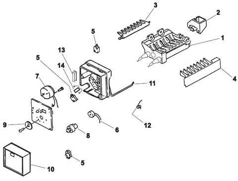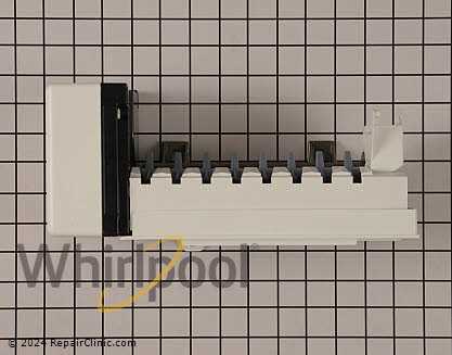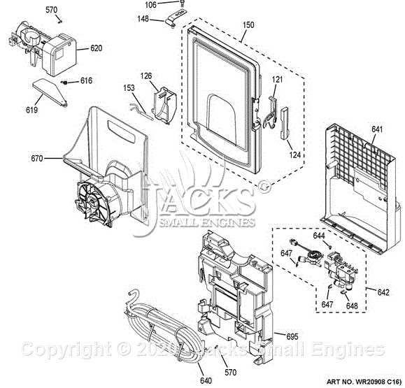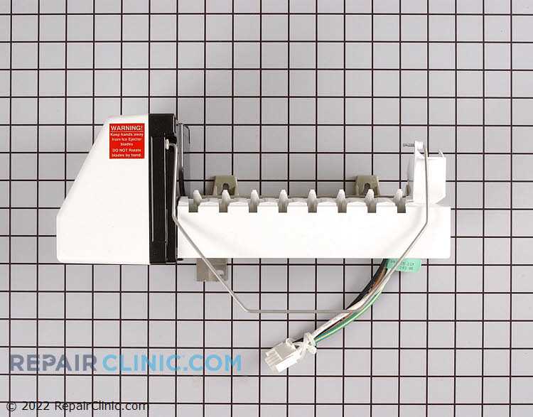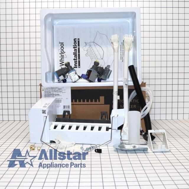
Every household relies on various appliances that simplify daily tasks and provide comfort. One essential device found in many homes operates to offer cool, refreshing relief, especially during warmer months. For this device to function effectively, it is built with several integral elements working in harmony. Knowing the role and placement of these components can greatly assist in keeping it running efficiently and may prove useful in diagnosing potential issues.
The structure of this cooling unit is designed with specialized sections, each playing a distinct role. Familiarizing yourself with these key areas can help in recognizing any unusual symptoms or wear and tear. A clear layout of each section and its interconnections aids not only in understanding how the unit works but also in identifying the primary sources of malfunctions or inefficiencies over time.
In the following sections, we will delve into the layout and connections that make this appliance function smoothly. You’ll gain insight into how each part contributes to the overall performance and how small adjustments or replacements can significantly impact its operation. This knowledge can empower homeowners to address minor issues confidently and maintain their appliance in optimal condition.
Essential Components of a GE Ice Maker

This section covers the main elements required for a typical cooling and dispensing unit to produce and deliver solid water formations. These devices rely on several interconnected parts that work together efficiently to achieve their intended functions. Each component has a dedicated role, from initial water intake to final delivery, ensuring reliable and consistent operation.
Key Elements of the Cooling and Delivery Mechanism
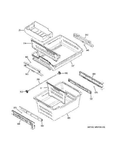
Understanding the primary components of this system helps in identifying potential issues and maintaining optimal performance. Here are some of the crucial parts involved in the process:
| Component | Description | ||||||||||||||||
|---|---|---|---|---|---|---|---|---|---|---|---|---|---|---|---|---|---|
| Water Inlet Valve | Controls the flow of water into the system, ensuring an adequate supply for each cycle. | ||||||||||||||||
| Evaporator | Responsible for transforming liquid into solid form, using a cooling process to achieve desired results. | ||||||||||||||||
| Control Module | Manages the timing and sequence of operations, coordinating each step for consistent output. | ||||||||||||||||
| Thermostat | Regulates the temperature within the unit, maintaining necessary levels to support efficient formation. | ||||||||||||||||
| Dispenser Assembly | Facilitates the release and access to the final product, ensuring
Overview of the GE Ice Making Mechanism
In exploring the intricate system within GE appliances that produces frozen cubes, we delve into the inner workings of a mechanism designed to transform water into solid forms for cooling purposes. This mechanism operates through a sequence of interconnected components, each playing a crucial role in the overall function.
Understanding these foundational aspects illuminates the complexity behind this vital household technology, highlighting the synergy between engineering precision and practical application. Water Supply and Filter Assembly
The assembly responsible for providing and purifying the essential liquid component plays a crucial role in ensuring optimal performance. This system not only supplies the necessary fluid but also incorporates filtration to maintain cleanliness and safety. Understanding its components and functionality is vital for efficient operation. Connection Elements: The initial part of this assembly includes various connections that facilitate the flow of liquid from the main supply to the internal mechanisms. These connections must be securely fitted to prevent leaks and ensure a steady supply. Filtration System: A reliable filtering mechanism is essential for removing impurities. It typically involves a cartridge or mesh system designed to trap contaminants, thereby ensuring that only purified liquid reaches the internal components. Flow Regulation: The assembly also features components that regulate the flow rate, ensuring that the right amount of liquid is delivered at all times. This regulation is vital for maintaining efficiency and preventing any potential overflow. Maintenance Considerations: Regular checks and maintenance of the connection elements and filtration system are recommended. Replacing filters at scheduled intervals helps to sustain performance and prolong the life of the entire assembly. Ice Mold Tray and Its Role
The component responsible for shaping frozen water plays a crucial role in the overall functionality of refrigeration appliances. Its design and operation are essential for producing uniform and properly formed blocks of frozen liquid, catering to various needs and preferences. This crucial element operates through a series of processes that ensure efficiency and reliability. Here are some key aspects of its role:
Understanding the significance of this component highlights its impact on everyday convenience and enjoyment, making it an indispensable part of modern refrigeration solutions. Thermostat and Temperature Control Parts
This section explores crucial components responsible for regulating temperature and ensuring optimal performance within refrigeration units. Understanding these elements is essential for maintaining efficiency and preventing malfunction. Types of Temperature RegulatorsTemperature regulators come in various forms, each designed to perform specific functions. From mechanical devices that rely on bimetallic strips to advanced electronic sensors, these regulators help maintain the desired climate by adjusting cooling cycles accordingly. Importance of Calibration
Proper calibration of temperature controls is vital for efficient operation. Misaligned settings can lead to overcooling or insufficient cooling, impacting overall functionality and energy consumption. Regular checks and adjustments ensure the system operates at its ultimate efficiency. Functions of the Auger and Motor
The auger and motor play crucial roles in the efficient operation of a refrigeration appliance designed for producing frozen cubes. Their collaboration ensures that the entire system functions smoothly, allowing for a steady flow of frozen product when needed. The auger is responsible for moving the frozen substance from the storage area to the dispensing outlet. Its spiral design facilitates the transport process, helping to break apart and transfer the frozen cubes with minimal effort. Meanwhile, the motor powers the auger, providing the necessary energy to rotate it effectively, ensuring that the substance is delivered quickly and efficiently.
This synergy between the two components not only enhances performance but also contributes to the overall longevity of the appliance, ensuring consistent and reliable service over time. Understanding the Defrost System
The defrost mechanism plays a crucial role in maintaining optimal functionality by preventing the buildup of frost and ensuring efficient operation. Understanding its components and processes can help in troubleshooting and maintaining overall performance. Key elements of the defrost system include:
Proper maintenance of these components is essential for seamless operation:
By understanding and maintaining the defrost system, users can ensure longevity and efficiency of their refrigeration units. Control Board and Power Connections
The control mechanism and its associated electrical connections play a crucial role in the functionality of refrigeration units. Understanding these components is essential for troubleshooting and ensuring optimal performance.
Proper maintenance of these elements is vital for reliability and efficiency, allowing for smooth operation over time. Common Signs of Component Wear
Over time, various elements within a refrigeration unit may exhibit signs of deterioration. Recognizing these indicators early can prevent further complications and extend the lifespan of the appliance. Pay attention to subtle changes in performance or unusual behaviors that suggest underlying issues. Unusual Noises: One of the most common symptoms of wear is the emergence of strange sounds, such as grinding or buzzing. These noises often indicate that moving parts are struggling or that components are misaligned. Inconsistent Performance: If the machine experiences fluctuations in temperature or struggles to produce its intended output, it may signal that internal mechanisms are failing. This inconsistency can lead to decreased efficiency and higher energy consumption. Physical Wear: Visible signs of wear, such as cracks or corrosion, can compromise the integrity of various components. Regular inspections can help identify these issues before they lead to complete failure. Frequent Cycling: An appliance that cycles on and off more often than usual may be dealing with a malfunctioning thermostat or a failing compressor. This behavior not only affects performance but can also increase wear on the unit. Water Leaks: Any accumulation of water around the unit can indicate a problem with seals or drainage systems. Leaks can lead to further damage if not addressed promptly. By staying vigilant and observing these signs, users can take proactive measures to maintain their appliances and avoid costly repairs. |
