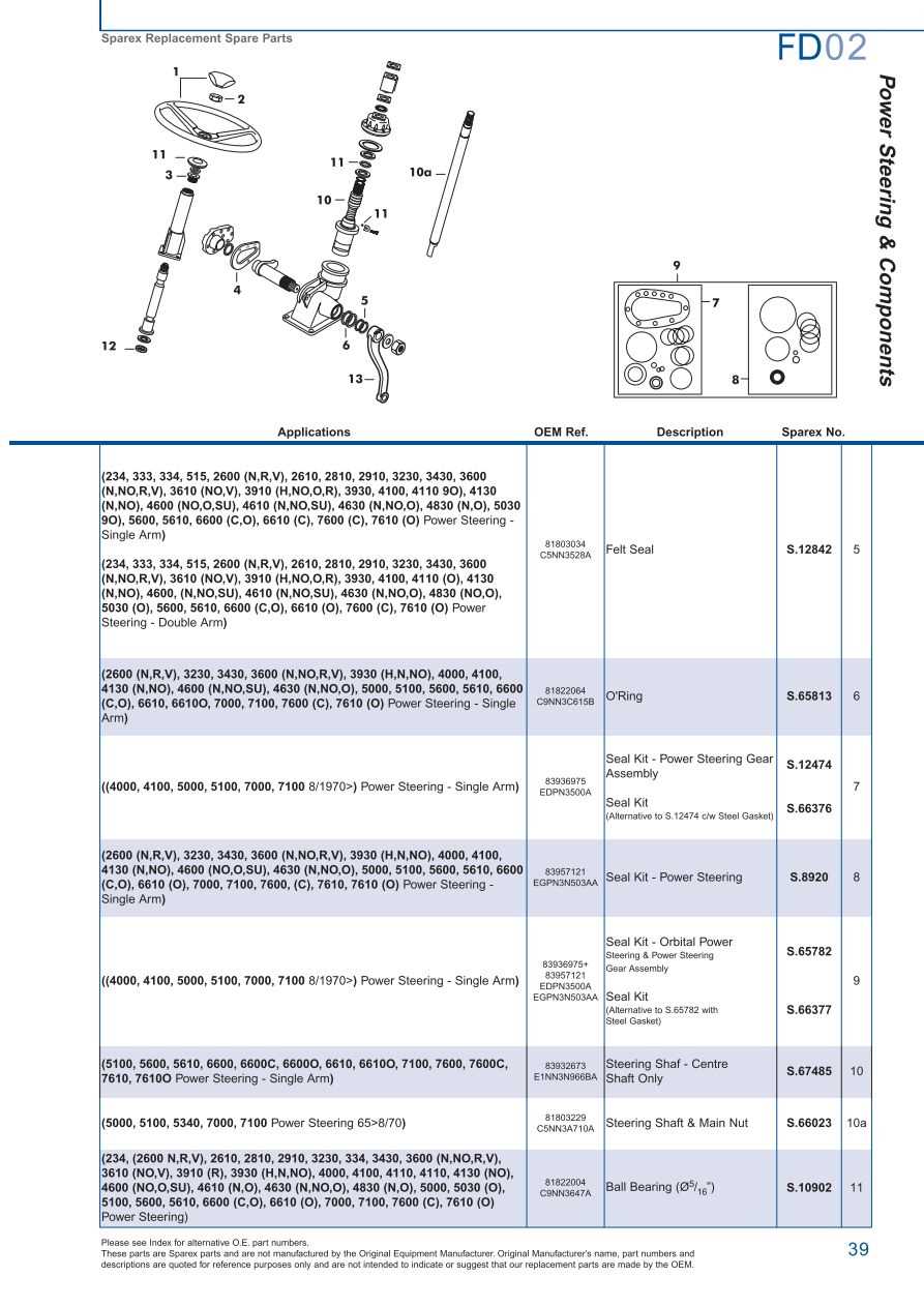
In the realm of agricultural equipment, having a comprehensive understanding of machinery elements is crucial for effective maintenance and operation. These complex machines are designed with numerous components that work in harmony to ensure optimal performance in various farming tasks.
For anyone involved in the upkeep of such machinery, familiarity with the arrangement and function of each individual piece is essential. Knowing how each component interacts can significantly enhance the efficiency of repairs and replacements, ultimately prolonging the life of the equipment.
By examining a visual representation of these components, one can easily identify the various elements and their specific roles. This knowledge not only aids in troubleshooting but also empowers operators to make informed decisions about necessary interventions and upgrades.
Essential Components of Ford 6610 Tractor
The functionality of a modern agricultural vehicle depends on various critical systems working in harmony. Each component serves a specific purpose to ensure that the machine can perform tasks efficiently, whether it’s plowing, hauling, or tilling. Understanding the key elements of these machines is crucial for maintenance and troubleshooting. Below is an overview of the most vital systems and parts that contribute to the tractor’s operation and longevity.
Engine and Powertrain
The engine is the heart of the vehicle, providing the power necessary to perform heavy-duty tasks. It is paired with the powertrain system, which transmits this power to the wheels. Key components in this category include:
- Engine block
- Fuel system
- Cooling system
- Transmission
- Drive shaft
- Axles
Hydraulic and Steering Systems
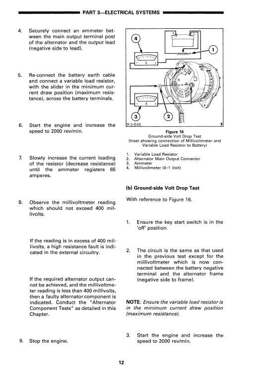
Efficient lifting, tilting, and steering mechanisms rely on the hydraulic system. This system facilitates smooth operation of implements and ensures precise control over the vehicle’s movement. Important elements of this system are:
- Hydraulic pump
- Control valves
- Steering cylinders
- Power steering pump
- Reservoir and hoses
Each of these systems is critical for the effective operation and maneuverability of the machine in diverse agricultural settings. Proper maintenance of these components ensures longevity and reduces downtime for repairs.
Understanding the Ford 6610 Parts Layout
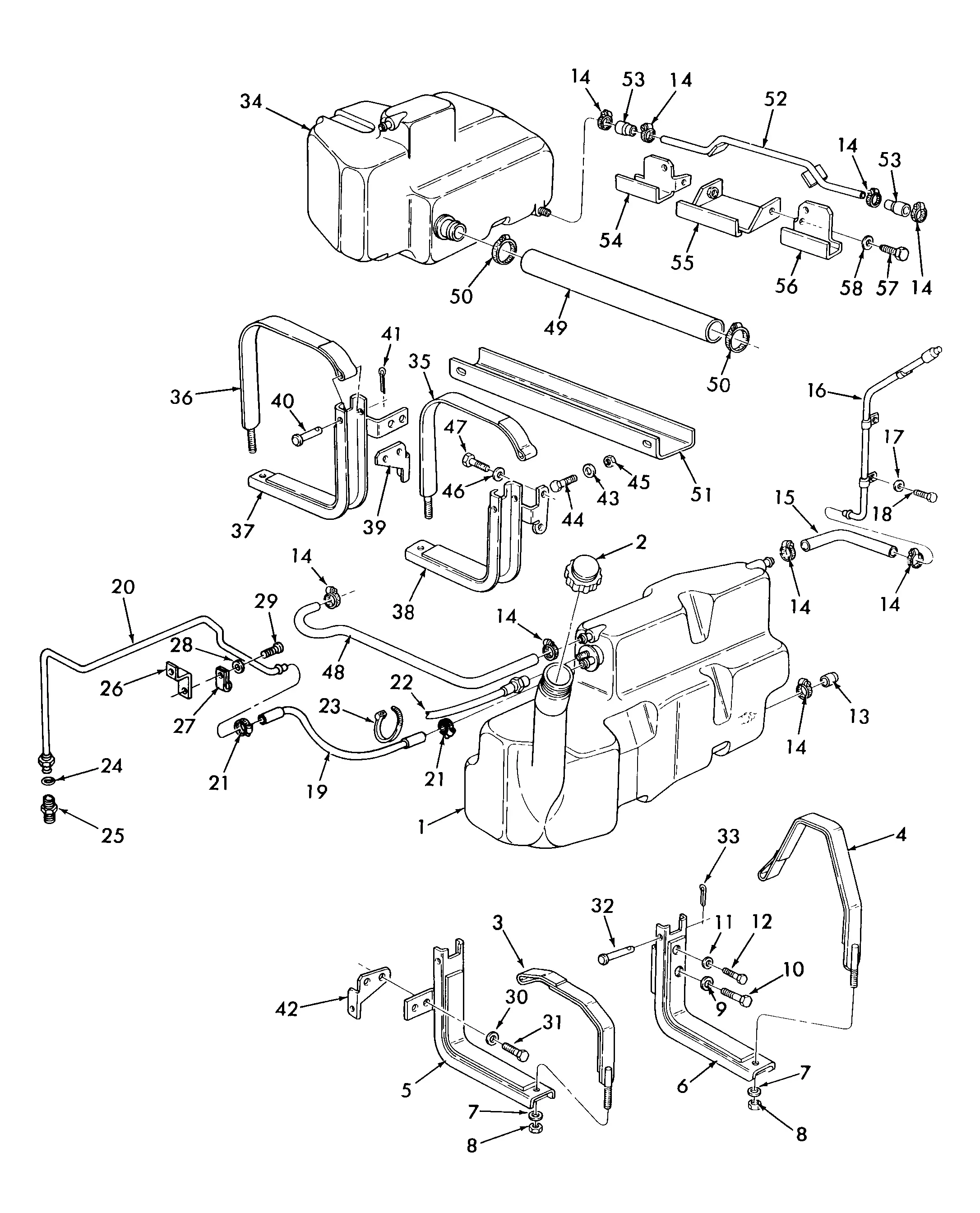
This section provides a comprehensive overview of the assembly arrangement for a well-known agricultural machine. Grasping the structure and components of this model is crucial for maintenance, repair, and effective operation. A clear understanding of how each element interacts ensures that users can efficiently troubleshoot and optimize performance.
Key Components Overview
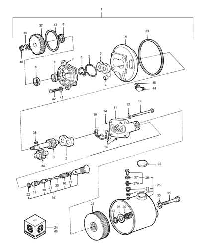
The functionality of this equipment relies on several essential elements, each playing a specific role in the overall operation. Familiarity with these components can enhance both performance and longevity.
| Component | Description |
|---|---|
| Engine | The power source that drives all operations. |
| Transmission | Transfers power from the engine to the wheels. |
| Hydraulic System | Facilitates the movement of attachments and implements. |
| Electrical System | Manages the lighting, ignition, and other electronic functions. |
Importance of Understanding Layout
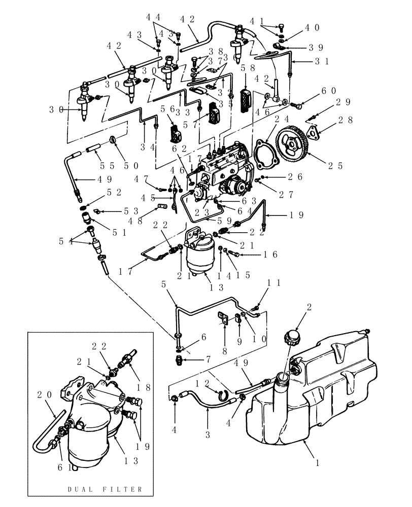
Recognizing how these elements are organized helps in identifying potential issues and conducting effective repairs. Knowledge of the assembly layout is indispensable for both novice and experienced operators, ensuring that every task can be performed with confidence and accuracy.
Key Engine Parts of the Ford 6610
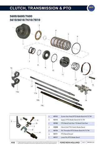
The internal combustion engine consists of several critical components that work in harmony to ensure optimal performance. Understanding the primary elements of this system is essential for maintenance, repair, and efficient operation. Each part plays a specific role, from initiating power generation to managing exhaust gases. This section focuses on the most crucial engine components that contribute to the functionality and longevity of the machine.
Crankshaft and Pistons
The crankshaft is a central component that converts the linear motion of the pistons into rotational motion. The pistons, moving up and down within the cylinders, are connected to the crankshaft via connecting rods. As the combustion process occurs, the force exerted by the expanding gases pushes the pistons, which in turn rotate the crankshaft, generating the mechanical energy needed to drive the vehicle. Proper alignment and lubrication are essential for these parts to function smoothly.
Fuel System and Injection Components
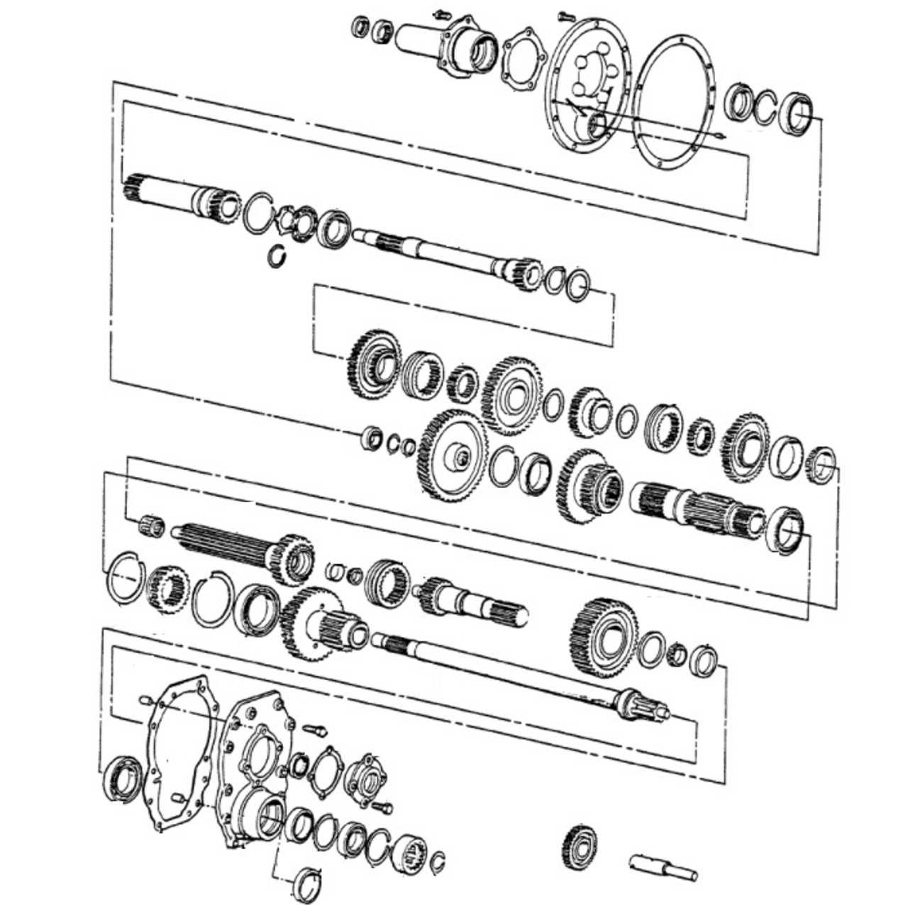
The fuel system, including injectors and the fuel pump, ensures that the engine receives the correct amount of fuel at the right time. Injectors spray the fuel into the combustion chambers, where it mixes with air to form a combustible mixture. The fuel pump regulates the fuel flow to maintain consistent pressure. Maintaining these components is critical for efficient fuel combustion, proper engine performance, and minimizing emissions.
Transmission and Gearbox Overview
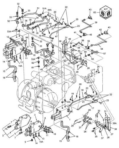
The transmission and gearbox are critical components in any machinery, playing a vital role in converting engine power into usable torque and speed. These systems enable vehicles to operate efficiently across various conditions by allowing the operator to select the appropriate gear ratios. Understanding their design and function is essential for maintenance and repair.
Transmission systems typically consist of several gears and shafts that facilitate the transfer of power from the engine to the drive wheels. They can be categorized into manual and automatic types, each with unique operational mechanisms. Manual transmissions require the driver to change gears manually, while automatic systems adjust gear ratios automatically based on speed and load, providing convenience and ease of use.
The gearbox houses the gear sets that manage torque distribution. It often includes various components such as clutches, synchronizers, and output shafts, which work together to ensure smooth operation. Proper lubrication and regular inspections are crucial to prevent wear and ensure longevity, as any malfunction can lead to significant performance issues.
In summary, a thorough understanding of the transmission and gearbox systems is essential for effective operation and maintenance. Regular checks and timely repairs can enhance the durability and performance of these integral components, ensuring reliable functionality in demanding environments.
Hydraulic System Components Explained
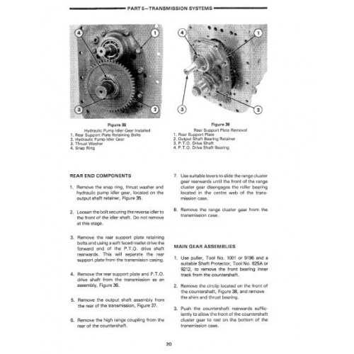
The hydraulic system is a crucial aspect of machinery, relying on fluid dynamics to perform various functions efficiently. Understanding the individual elements that make up this system is essential for maintenance and optimization. Each component plays a vital role in ensuring the smooth operation of hydraulic machinery, contributing to overall performance and reliability.
At the core of the hydraulic system are the pump and reservoir, which work together to circulate fluid. The pump generates the necessary pressure to move the hydraulic fluid, while the reservoir holds the fluid and helps maintain a consistent supply. These two components are fundamental to the system’s functionality and efficiency.
Next, we have the actuators, which convert hydraulic energy into mechanical motion. These can include cylinders and motors that facilitate the movement of various parts of the equipment. The seamless operation of these actuators is critical for tasks such as lifting, pushing, and rotating, making them indispensable in heavy machinery.
Additionally, valves play a significant role in controlling the flow and direction of the hydraulic fluid. By regulating the pressure and flow rate, these devices ensure that the system operates safely and effectively. Various types of valves, including directional, pressure, and flow control valves, are employed to manage the complexities of the hydraulic network.
Finally, hoses and fittings connect all the components, allowing for the efficient transfer of fluid throughout the system. The integrity of these connections is vital, as leaks or blockages can lead to performance issues and potential hazards. Proper maintenance and timely replacements of these parts are essential for the longevity and reliability of hydraulic systems.
Maintenance of the Ford 6610 Parts
Proper upkeep of agricultural machinery is essential for ensuring longevity and optimal performance. Regular inspection and care of various components not only prevent unexpected breakdowns but also reduce the likelihood of costly repairs. Regular checks of key elements, such as the engine, transmission, and hydraulic systems, are crucial in maintaining smooth operations and extending the lifespan of the machine.
Routine maintenance should focus on specific areas like fluid levels, filter conditions, and wear on mechanical parts. It is important to follow a maintenance schedule and keep records of completed tasks. Below is a breakdown of some common components that require periodic attention:
| Component | Maintenance Task | Frequency |
|---|---|---|
| Engine | Change oil and filter, check coolant levels, inspect belts | Every 100 hours of operation |
| Hydraulic System | Check fluid levels, inspect hoses and seals for leaks | Every 200 hours of operation |
| Transmission | Check for leaks, inspect fluid quality, change fluid if necessary | Every 500 hours of operation |
| Brakes | Inspect pads, check for wear, ensure proper fluid levels | Every 100 hours or after heavy use |
| Cooling System | Flush radiator, check hoses, ensure no leaks | Every 200 hours of operation |
By adhering to a maintenance schedule and using high-quality lubricants and parts, the reliability and performance of the machine can be ensured, minimizing downtime and repair costs over time.
Electrical System and Wiring Diagrams
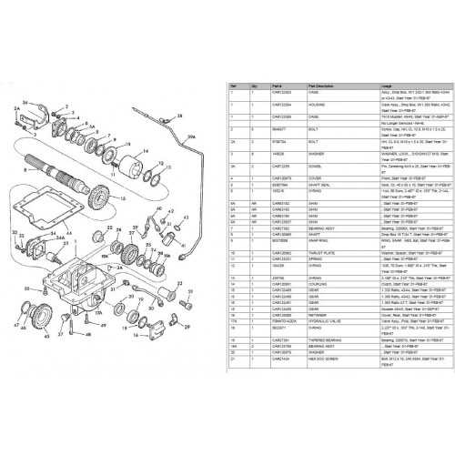
The electrical architecture of agricultural machinery is crucial for optimal performance and reliability. Understanding the layout and connections of various components ensures efficient troubleshooting and maintenance. A clear representation of the circuitry can significantly aid in identifying issues and implementing effective solutions.
Component Overview
This section highlights the essential elements within the electrical framework, including switches, relays, and sensors. Each part plays a vital role in the overall functionality, contributing to tasks such as starting the engine and controlling various systems. Familiarity with these components enhances operational efficiency.
Wiring Connections
Mapping the connections between different electrical parts is fundamental for diagnosing faults. Detailed illustrations can provide insights into proper routing and potential areas of concern. By delving into the specifics of these connections, users can achieve a more profound understanding of their machinery’s electrical capabilities.
Replacing Worn-Out Parts Effectively
Maintaining the functionality of machinery is crucial for optimal performance. Regularly updating components that show signs of wear can prevent costly breakdowns and ensure smooth operation. Understanding the process of replacing these elements effectively is essential for any operator or technician.
Here are some key steps to consider when addressing worn components:
- Identification: Regularly inspect machinery to identify components that are deteriorating. Look for:
- Unusual noises during operation
- Visible signs of wear, such as cracks or breaks
- Decreased performance or efficiency
lessCopy code
- Tracking maintenance history
- Ordering the correct replacements
- Reputable manufacturers
- Reviews and feedback from other users
- Using the right tools
- Ensuring proper alignment and fit
- Testing the machinery post-installation
By following these steps, operators can ensure that their machinery remains in peak condition, minimizing downtime and enhancing overall efficiency.