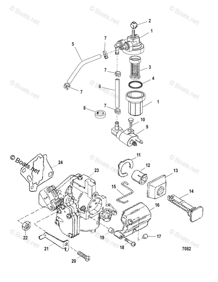
When dealing with any marine engine, it is crucial to have a clear understanding of the internal and external mechanisms that allow it to function efficiently. Every piece plays a role in the overall performance, from the fuel system to the ignition components. To keep a boat running smoothly, familiarity with its key elements is essential.
Whether you’re maintaining, repairing, or upgrading, knowing how various elements connect and work together will make any task easier. Proper identification of each element ensures smoother troubleshooting and better handling of any issues that may arise during use.
This guide provides detailed insights into the essential components, helping boat owners and technicians easily navigate and maintain their marine engines. By focusing on these systems, you can enhance both the longevity and reliability of your equipment.
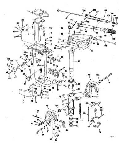
Overview of Key Components in 25 HP Marine Engine
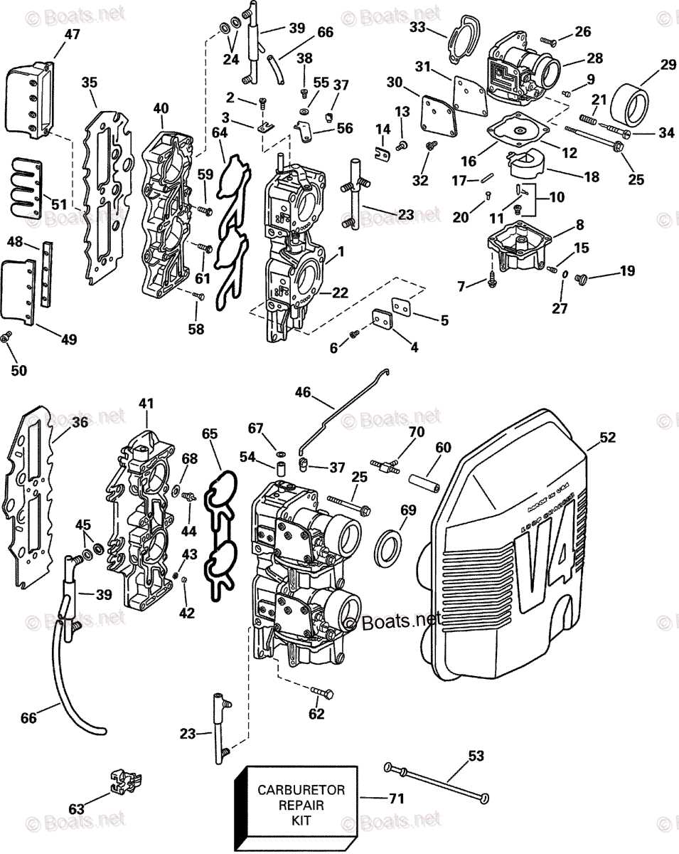
The structure of any marine propulsion system is built around a set of essential elements that ensure smooth operation and power delivery. Understanding these components is crucial for efficient maintenance and troubleshooting.
- Powerhead: The core of the engine, responsible for generating the necessary force to propel the boat. It houses internal mechanisms like the pistons and cylinders that convert fuel into power.
- Fuel System: This includes a series of components like the carburetor and fuel lines, which manage the flow of fuel into the engine for optimal performance.
- Ignition System: Responsible for igniting the fuel mixture, this system includes the spark plugs, coils, and associated wiring, ensuring the engine starts and runs smoothly.
- Cooling System: Designed to prevent the engine from overheating, this system circulates water through various channels, regulating the temperature and ensuring longevity.
- Lower Unit: The section that connects the power source to the propeller, t
Identifying Vital Engine Parts and Functions
Understanding the key components and their roles within a motor system is essential for ensuring smooth operation and efficient performance. Each element plays a specific part in maintaining the engine’s overall functionality, and being able to recognize them helps in both maintenance and troubleshooting.
- Power Source Mechanism: The primary unit responsible for converting fuel into mechanical energy, enabling motion and power generation.
- Cooling System: Critical for regulating temperature, preventing the engine from overheating during extended use. This system ensures the motor remains at optimal operating conditions.
- Ignition Setup: Initiates the combustion process by generating the necessary spark, ensuring the system starts reliably under various conditions.
- Fuel Delivery System: Controls the flow of fuel, ensuring the appropriate mixture reaches the combustion chamber, maximizing efficiency and output.
- Exhaust Mechanism: Channels out the byproducts of combustion, keeping the system clear of harmful gases and maintaining performance.
Familiarity with these fundamental components and their purposes enables better maintenance
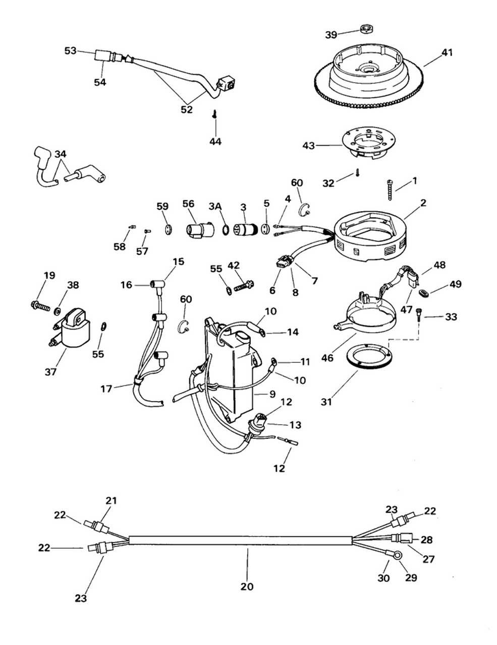
Understanding the Ignition System Layout
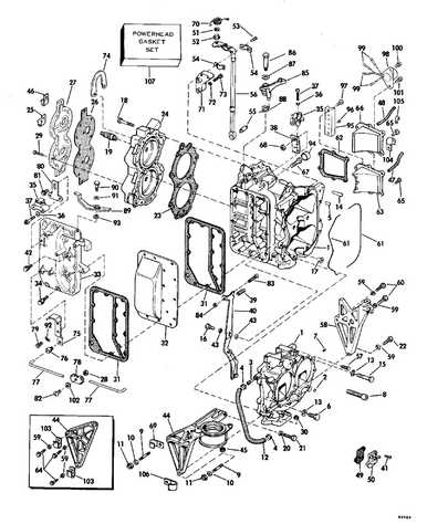
The ignition system plays a vital role in ensuring smooth and efficient operation. By delivering the necessary electrical charge, it helps in starting the engine and maintaining stable performance. A well-organized system ensures the right timing and precision in the combustion process, allowing for optimal power and fuel efficiency. Recognizing how each element interacts can assist in troubleshooting and maintaining the system’s reliability.
Key Components and Their Roles
The system typically consists of several essential components that work together to generate and deliver the spark needed for ignition. These include the ignition coil, spark plugs, and control units. Each component must function in harmony to create the right conditions for combustion. The timing of the spark is also crucial, as it ensures that the fuel-air mixture ignites at the perfect moment.
Importance of Proper Maintenance
Regular maintenance of the ignition system is crucial to prevent misfires or engine failures. Checking the connections, cleaning the spark plugs, and ensuring the wiring is intact can significantly extend the life of the system.
Fuel System Components and Their Roles
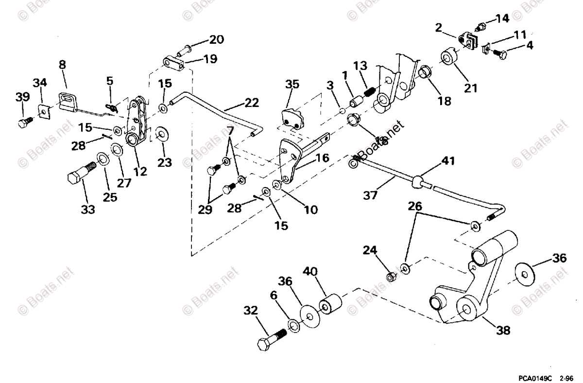
The fuel delivery system in any motorized equipment ensures the efficient flow and utilization of energy sources required for operation. It includes various interconnected components that regulate, store, and distribute energy, ensuring smooth and consistent performance during use.
- Fuel Tank – Stores the necessary fuel, maintaining the system’s supply for continuous operation.
- Fuel Line – A channel that transports the stored fuel from the tank to other critical components, ensuring steady flow.
- Fuel Filter – Removes impurities and debris, preventing them from entering sensitive parts of the system, which could cause blockages or damage.
- Fuel Pump – This part generates the necessary pressure to move fuel through the system, ensuring that it reaches the engine efficiently.
- Carburetor – Mixes fuel with air in precise ratios to create the optimal conditions for combustion, driving the motor efficiently.
Each of these components plays a crucial role in the overall functionality of the motor, working together to ensure efficient energy utilization and reliable performance.
Water Cooling Mechanism: Structure and Operation
The cooling system plays a vital role in ensuring the efficient and safe operation of the engine, maintaining optimal temperature levels. Without proper regulation of heat, the machinery can overheat, leading to performance issues and potential damage. The cooling process helps to dissipate excess warmth generated during operation, keeping all components within safe temperature limits.
Key Components of the Cooling System
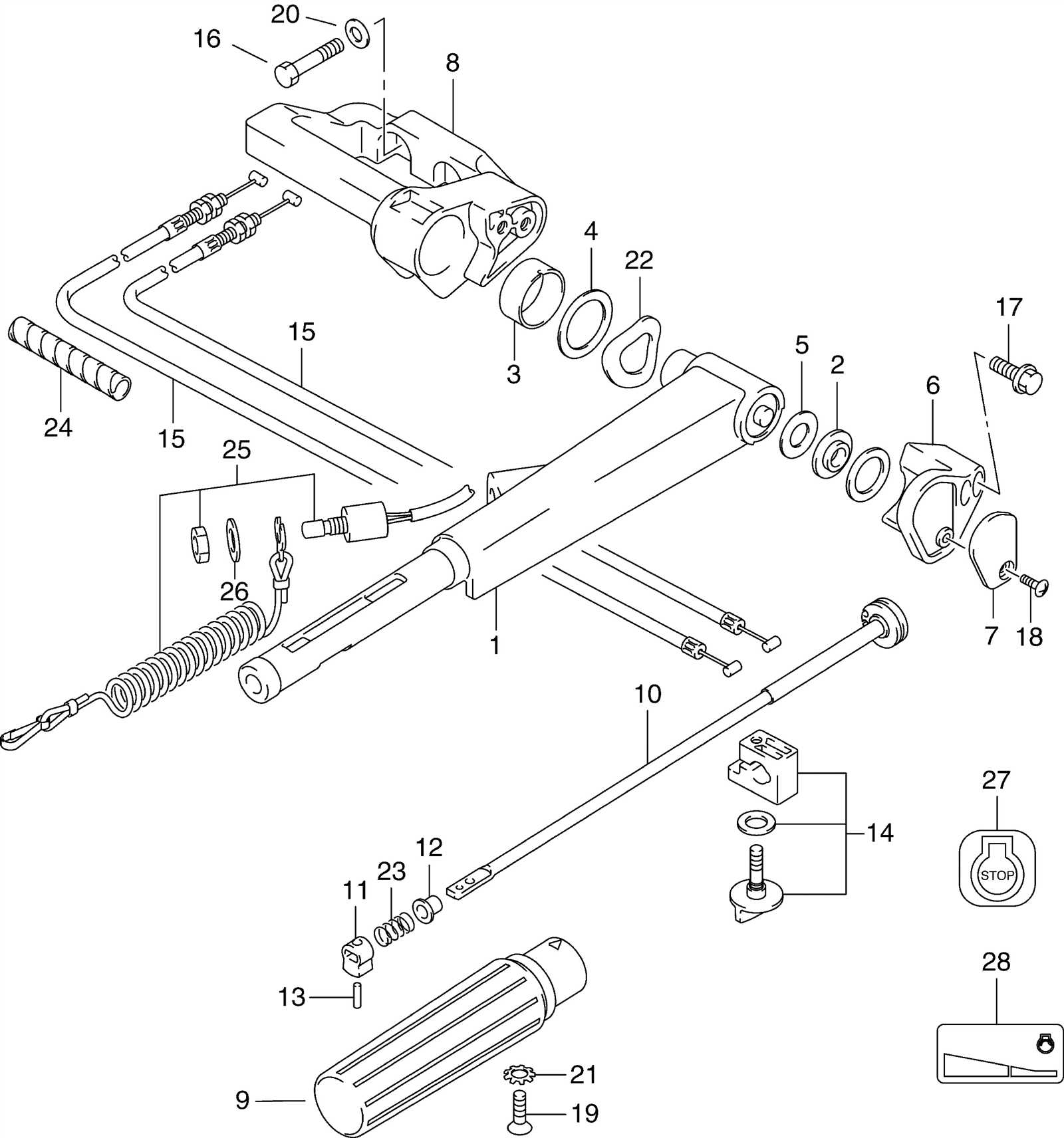
This mechanism relies on several essential elements working in harmony. A pump draws in water from the surrounding environment, directing it through specific channels. As the liquid passes through, it absorbs heat from critical areas of the engine, thus preventing any potential thermal stress. The system is designed to continuously cycle the water, ensuring a steady flow to keep temperatures in check.
How the System Operates
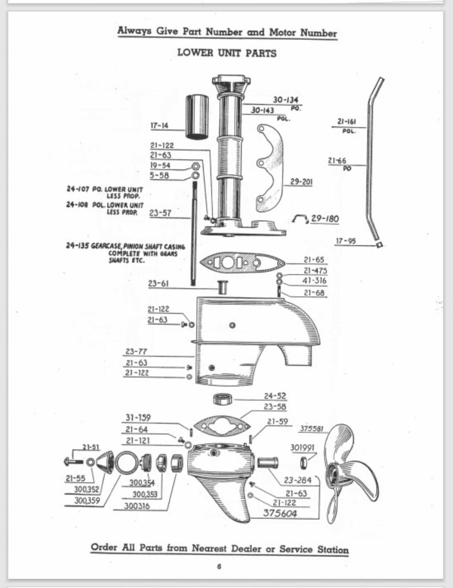
Once water enters the system, it is strategically routed to areas that generate the most heat. After absorbing the excess warmth, the heated water is expelled, allowing cooler water to enter and repeat the process. This constant exchange enables the engine to maintain stable performance levels, even during prolonged use or under heavy loads.
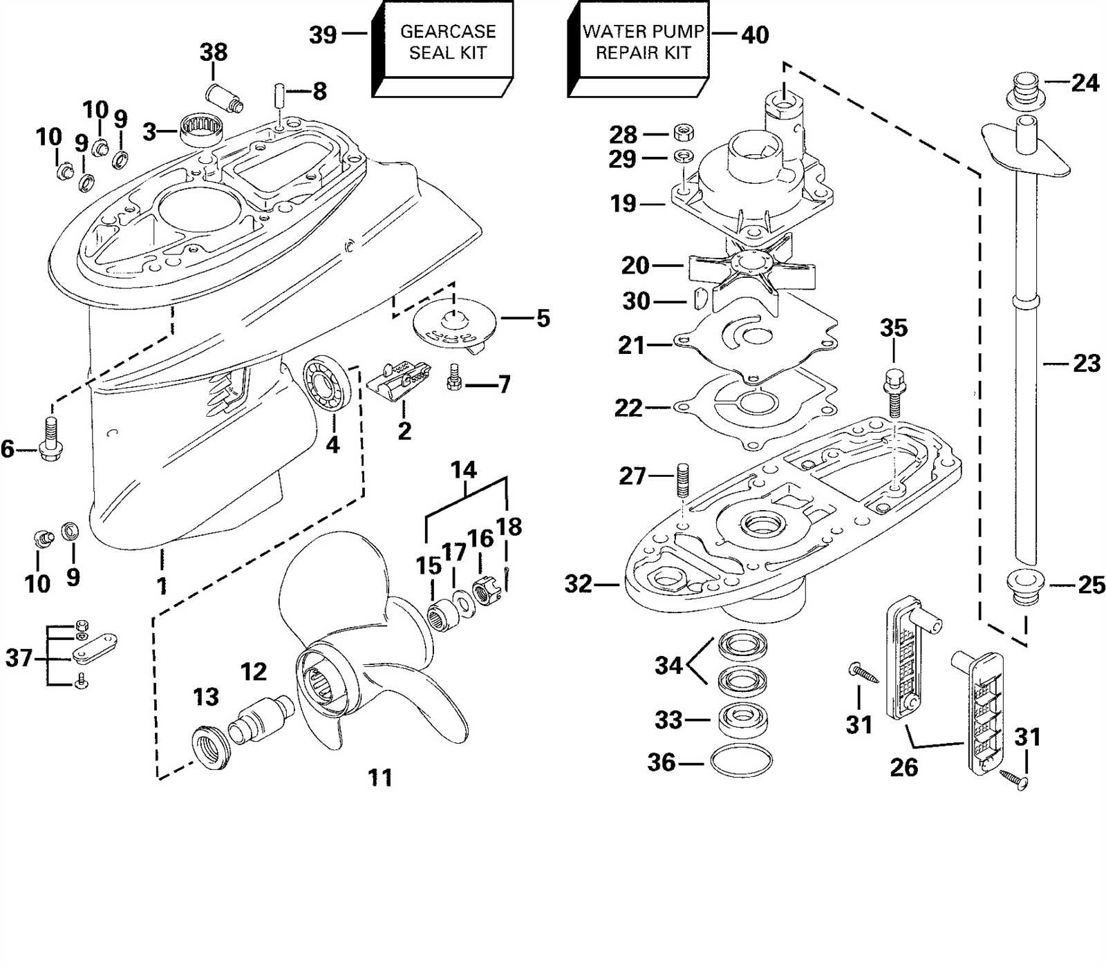
Exploring Propeller and Shaft Assembly
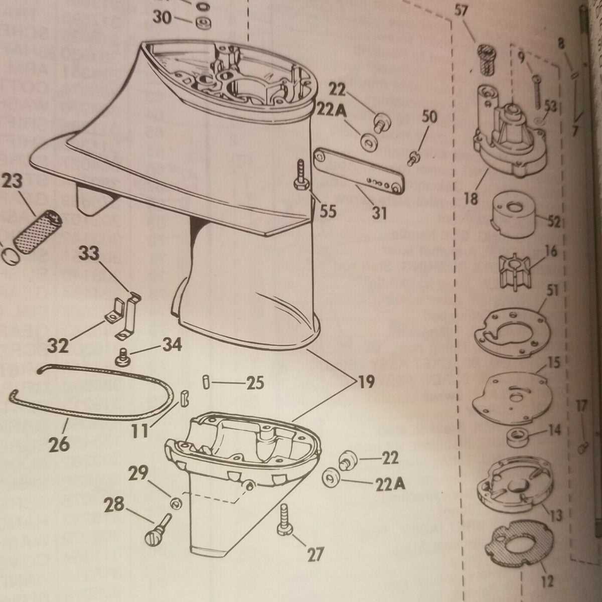
The interaction between the rotating blades and the drive mechanism is crucial for optimal performance on the water. Understanding the components involved in this assembly provides insight into their functionality and importance in marine propulsion systems. A well-designed configuration can significantly enhance efficiency and maneuverability, ensuring a smooth experience while navigating various aquatic environments.
Key Components of the Assembly
The primary elements of this assembly include the rotating blades, the central hub, and the drive shaft. The blades, often crafted from durable materials, are designed to efficiently convert engine power into thrust. The hub serves as the connection point for the blades and the shaft, ensuring stability and precision during operation. The drive shaft transmits rotational energy from the engine to the propeller, allowing for effective propulsion.
Maintenance and Performance Optimization
Regular inspection and maintenance of the assembly are vital for sustaining performance and preventing potential issues. Checking for signs of wear, corrosion, or damage is essential to ensure that all components operate harmoniously. Additionally, optimizing the pitch and diameter of the blades can enhance thrust and fuel efficiency, contributing to a more effective and enjoyable boating experience.
Electrical Wiring and Connections Overview
Understanding the intricacies of electrical connections is vital for ensuring optimal performance and safety in marine equipment. Proper wiring not only facilitates efficient operation but also prevents potential malfunctions. This section delves into the fundamental aspects of electrical connectivity, emphasizing key components and their roles in maintaining a reliable system.
The wiring system consists of various elements that work in unison to provide power and control signals to different parts of the machinery. Each component serves a specific function, and a clear understanding of these roles is essential for effective maintenance and troubleshooting.
Component Function Battery Supplies power to the electrical system. Fuse Protects the circuit by breaking the connection in case of overload. Wiring Harness Connects various electrical components, ensuring organized routing. Connectors Facilitate secure connections between different wiring segments. Switches Control the flow of electricity to specific components. Common Wear Parts and Maintenance Tips
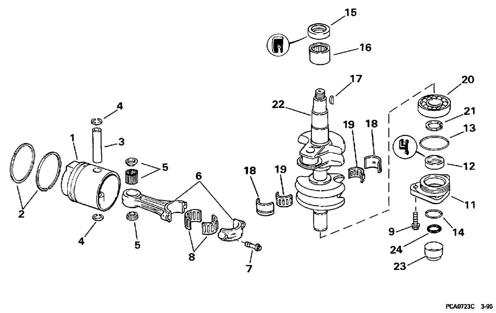
Regular upkeep of marine engines is essential for optimal performance and longevity. Various components are subject to wear and tear due to exposure to harsh conditions and continuous use. Understanding which elements require attention can greatly enhance the reliability of your equipment.
Here are some frequently worn components to monitor:
- Propellers: Inspect for nicks and bends that can affect efficiency.
- Fuel Filters: Replace regularly to ensure clean fuel supply and prevent engine damage.
- Water Pumps: Check for blockages and wear, as efficient cooling is crucial.
- Spark Plugs: Examine for deposits and replace if necessary for optimal ignition.
- Hoses and Clamps: Look for cracks and deterioration to maintain proper fluid flow.
To ensure these components remain in good condition, consider the following maintenance tips:
- Perform regular inspections before and after each outing.
- Keep the engine clean to prevent corrosion and buildup.
- Follow a consistent schedule for part replacements based on usage.
- Utilize quality replacement components that meet manufacturer specifications.
- Consult a professional mechanic for any major repairs or concerns.
Adhering to these guidelines can significantly extend the life of your marine engine and enhance its performance on the water.
How to Use a Parts Diagram for Repairs
Understanding the layout of components in a mechanical system is essential for effective maintenance and restoration. Utilizing a visual representation can significantly enhance the repair process by providing clarity and reference points. This guide will explore how to leverage such a representation for successful fixes.
Identifying Components
The first step in the repair process is recognizing the various elements involved. A visual guide allows you to:
- Quickly locate specific items.
- Understand the relationship between different parts.
- Make informed decisions regarding replacements or repairs.
Planning Your Approach
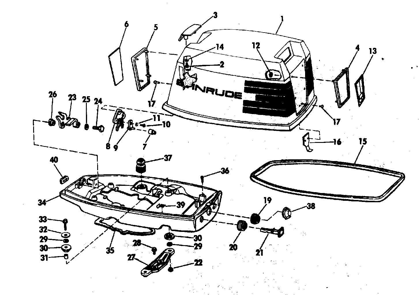
Once you’ve familiarized yourself with the components, it’s crucial to develop a strategy for your repair work. Consider the following steps:
- Gather all necessary tools and replacement items.
- Refer to the visual guide to plan the disassembly process.
- Document your progress to ensure correct reassembly.
By utilizing a visual reference, you can streamline your repair efforts, minimizing errors and enhancing overall efficiency.