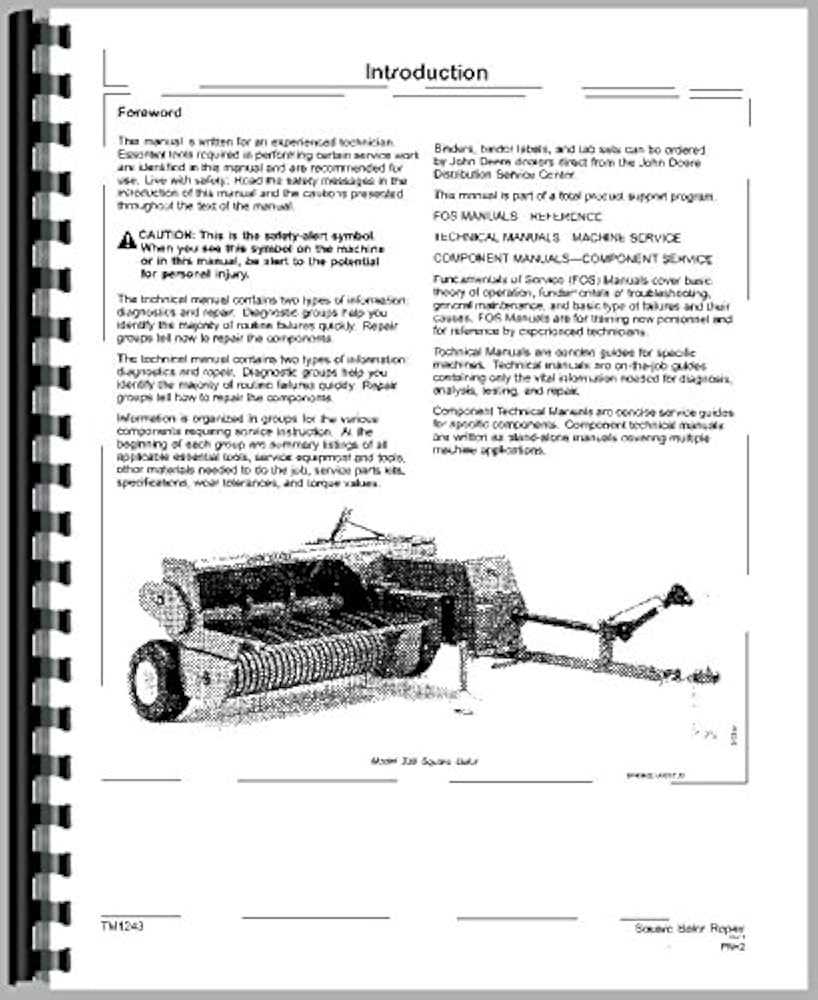
Understanding the intricate mechanics of farming machinery is essential for ensuring efficient operation and minimizing downtime. When working with large-scale agricultural equipment, knowing how each element fits together and functions is crucial for proper maintenance and repairs. By examining the internal layout of such machines, operators can identify potential issues before they escalate into costly problems.
In this section, we will explore the various assemblies and mechanisms that make up a specific piece of harvesting machinery. The focus will be on the critical elements that ensure smooth operation, from the main drive system to the smaller, yet equally important, components that aid in the overall efficiency. By breaking down each section and reviewing its purpose, users will gain a better appreciation for how these parts contribute to the machine’s functionality.
It is important to have a clear visual reference when working on these machines. A comprehensive illustration showing how the pieces connect and work together can serve as a valuable tool. By understanding these layouts, operators can confidently troubleshoot problems and make informed decisions regarding repairs and replacements.
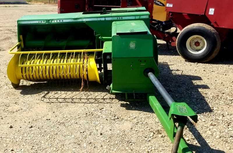
John Deere 336 Baler Overview
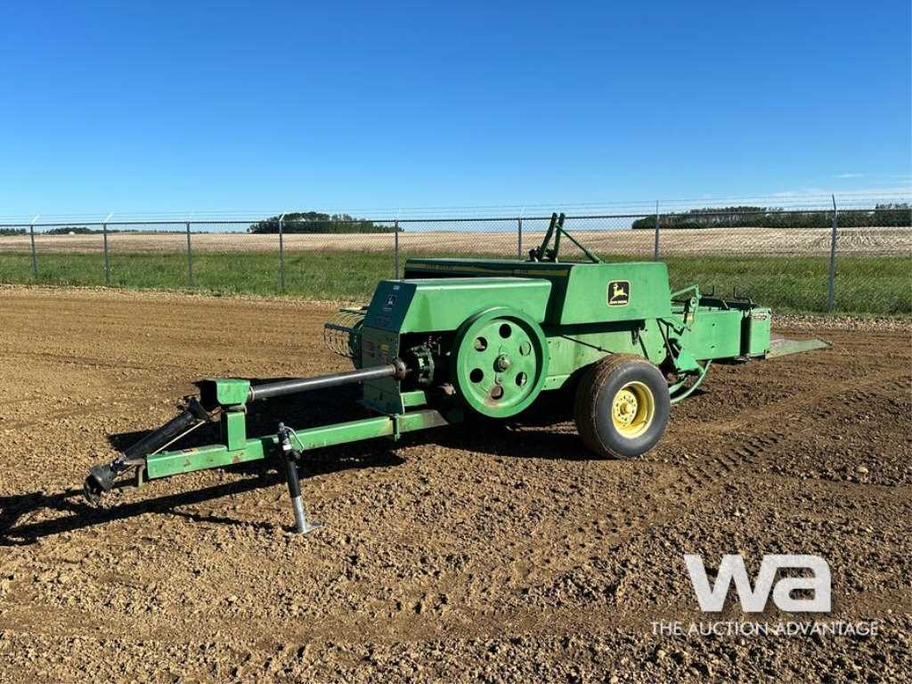
This machine is an essential piece of equipment for efficient hay production, known for its reliability and durable construction. Designed for use in large-scale farming operations, it combines simplicity with advanced functionality to meet the needs of modern agriculture. With its robust features, it ensures smooth operation in the field, allowing farmers to efficiently gather and compress crops for storage or transport.
Key Features
- Heavy-duty construction for long-lasting use in demanding environments.
- Efficient compression system for producing high-quality bales.
- Designed to handle a variety of crop types with ease.
- Simple operation and maintenance, reducing downtime.
- Adaptable to different farm sizes and conditions.
Benefits for Farmers
- Increased productivity with less manual labor required.
- Improved bale quality, ensuring efficient storage and transport.
- Cost-effective due to its long service life and low maintenance requirements.
- Easy to use with minimal setup, providing operational efficiency.
Essential Components of the 336 Baler
Understanding the key elements of this machine is crucial for ensuring its efficient operation. Each part plays a vital role in the overall function, from feeding material in to compacting it into neat bundles. A proper knowledge of these components allows for optimal maintenance and troubleshooting.
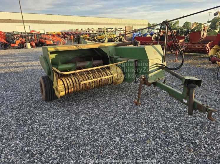
- Feed Mechanism: This section includes the parts responsible for gathering and feeding the material into the machine. It includes the pickup reel, feed forks, and the intake chamber, which work together to direct the crop towards the compression chamber.
- Compression System: The heart of the machine, where the gathered material is compacted into tightly bound units. This involves a series of rollers and belts, working in unison to squeeze the crop efficiently and evenly.
- Twine or Netting Mechanism: Once the material is compacted, this system wraps it into a secure form. Depending on the system, it may use twine or a net, ensuring the finished bundle remains intact during transportation and storage.
- Ejection System: The last part of the process is the removal of the finished bundles from the chamber. The ejection system typically consists of a kicker or a drop floor, which ensures smooth and efficient discharge of the compacted units.
Each of these components is crucial to the baling process, and regular maintenance can help prevent issues and keep the machine running efficiently. A good understanding of these essential elements ensures smoother operation and less downtime during the work season.
How to Identify Parts in the Diagram
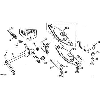
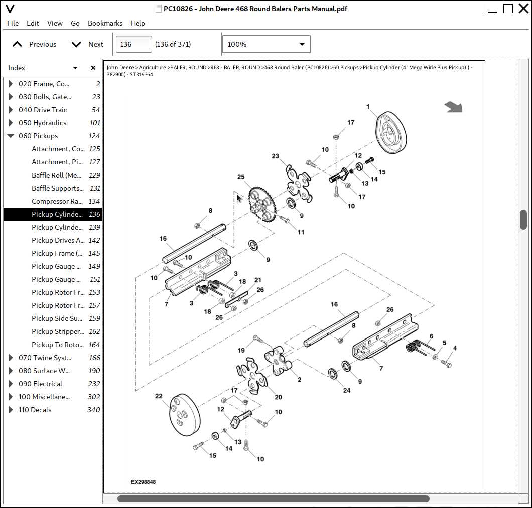
Understanding the layout of components within machinery is essential for maintenance and repair tasks. By examining visual guides, users can locate and identify individual elements crucial for operation. These references are designed to simplify the process of recognizing various segments and their connections within the system. Proper identification aids in troubleshooting, ensuring accurate replacements or repairs.
Steps to Identify Key Components
- Begin by locating the main assembly or section related to the task at hand.
- Look for labels or numbers next to each element, which usually correspond to the reference material or guide.
- Focus on unique shapes, sizes, or connections that distinguish one piece from another.
- Cross-reference with a manual or reference sheet to ensure accuracy.
Common Tips for Accurate Identification
- Pay attention to component orientation–some views may display parts from different angles.
- Check the scale or dimensions indicated in the reference for better understanding of each part’s real-life size.
- Ensure that all markings and codes are matched correctly with the corresponding section of the manual.
Maintenance Tips for Common Parts
Proper upkeep of machinery components is essential for ensuring their longevity and efficient operation. Regular maintenance prevents unexpected breakdowns and costly repairs. This section offers helpful guidelines for maintaining the most frequently encountered elements of your equipment.
- Lubrication: Regularly lubricate moving components to reduce friction and wear. Pay attention to areas prone to heat and pressure, such as bearings and chains.
- Cleaning: Clean dust, dirt, and debris from essential mechanisms after every use. Accumulation can lead to overheating and malfunctioning of critical parts.
- Check for Wear: Inspect key elements like belts, springs, and joints for signs of damage or excessive wear. Replace any worn-out parts promptly to prevent further damage.
- Alignment and Tension: Ensure that the alignment and tension of components, such as cables and belts, are adjusted correctly to maintain optimal performance.
- Fluid Levels: Regularly monitor and top up fluid levels, such as hydraulic oils, to keep the system running smoothly.
- Storage: When storing equipment, keep it in a dry, cool location to prevent rust and corrosion on metal surfaces.
Understanding the Bale Formation Mechanism
The process of creating tightly bound bundles of hay or straw is a crucial part of agricultural machinery. This operation relies on a complex system of mechanical components working together to gather, compress, and secure the material into a compact form. Key elements involved in this process include gathering the raw material, compressing it under pressure, and tying it with twine or wire to hold it together for storage or transport.
At the heart of this mechanism is a chamber where the material is compacted, ensuring uniform density and shape. The rotating mechanisms and driven belts contribute to the even movement of material, while the pressure rollers push it toward the compression zone. As the material is compressed, tension is maintained by a series of control systems that regulate the pressure applied. This ensures that each bale is formed with the desired consistency and strength.
Furthermore, the tying system plays an essential role in the completion of the process. Once the bale reaches the optimal size, a knotter system activates to wrap twine around it, securing the bundle for transport. The precision of this system is critical to ensure that the bale remains intact during handling and storage. The entire mechanism works seamlessly to create bales of uniform size and quality, maximizing efficiency in the field.
Tools for Repairing the 336 Baler
Maintaining agricultural machinery requires a variety of specialized tools to ensure smooth operation and longevity. For efficient upkeep and repairs, it is essential to have a well-equipped toolkit. The right set of instruments helps in diagnosing issues, replacing worn components, and ensuring that everything functions as it should. Knowing which tools to use for specific tasks allows for both time and cost savings.
Basic Tools Required
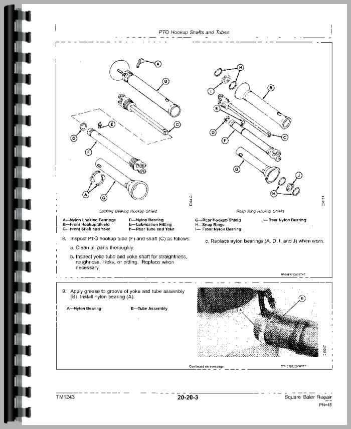
The foundation of any repair work includes basic hand tools such as wrenches, pliers, and screwdrivers. These tools are essential for disassembling parts, securing bolts, and making minor adjustments. Having a range of sizes available is crucial for dealing with different fasteners found on the machine.
Advanced Equipment for Heavy-Duty Repairs
For more complex repairs, such as replacing large components or making precise adjustments, advanced tools like hydraulic jacks, impact wrenches, and specialized diagnostic equipment are often necessary. These tools are designed to handle more demanding tasks and to provide accurate results, ensuring the equipment is back in top working condition.
Order and Replace Baler Components
Maintaining the functionality of agricultural machinery requires prompt attention to individual elements that may wear out or become damaged over time. To ensure optimal performance, it is essential to identify, acquire, and replace specific machine components as needed. This process involves understanding the key components of the equipment and ensuring that the replacements meet the manufacturer’s specifications.
Ordering New Components
When it becomes necessary to replace certain machine parts, it’s crucial to order replacements from a trusted supplier. Ensure that the parts are compatible with the existing system, and check the specifications provided by the manufacturer to avoid errors. A strong relationship with a reliable supplier can minimize downtime and provide access to genuine components that fit the system perfectly.
Replacing Worn-Out Elements
After receiving the replacement components, the next step is to proceed with the replacement process. It is important to follow safety protocols during disassembly and reassembly. Use the appropriate tools, and if necessary, consult a repair manual to correctly position the new parts. Proper installation can greatly extend the life of the equipment and maintain its efficiency.
Troubleshooting Issues with Key Parts
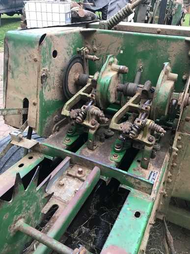
When working with agricultural machinery, addressing malfunctions of critical components is essential for smooth operation. Identifying the source of problems early can save time and prevent costly repairs. Whether dealing with the feeding system, drive mechanisms, or output assembly, understanding how to troubleshoot effectively is key to maintaining optimal performance.
- Feeding Mechanism: If the material is not being fed consistently, check for clogged or misaligned feed rollers. Ensure there are no blockages in the intake area, and inspect for worn-out belts that could be causing slippage.
- Drive System: Abnormal noises or irregular movement can indicate issues with the drive belt or chain. Inspect these components for wear and tension. If the drive is not functioning properly, verify the gear connections and lubrication levels.
- Compression Chamber: If the compression of the material is insufficient, check the plunger and its movement. Issues with the plunger’s motion could stem from damaged springs or misalignment of the drive system.
- Output Assembly: Problems with the final output can arise from blockages or worn parts in the knotter system. Ensure all components are properly aligned and free from debris, and replace any worn parts promptly to avoid breakdowns.
Regular inspection of these areas will help identify issues before they escalate. Always consult the manufacturer’s guidelines to ensure the correct maintenance procedures are followed, and replace faulty components immediately to avoid delays in operation.