Understanding the internal structure and configuration of machinery is essential for maintaining smooth operations in the field. This guide provides a detailed look at the key elements that make up essential farming equipment, offering valuable insights for both repair and optimization. By familiarizing yourself with these components, you can ensure efficient functioning and prolong the lifespan of your machinery.
Each section delves into specific mechanical elements, highlighting their roles and interactions within the larger system. Whether you’re dealing with worn-out elements or seeking to upgrade your equipment, this resource will help you identify critical aspects, ensuring a reliable performance in various conditions.
From vital power systems to intricate controls, this guide serves as a useful reference for anyone looking to understand and maintain agricultural machinery effectively. Discover how each piece contributes to the overall efficiency and reliability of your equipment, and learn best practices for upkeep and replacement.
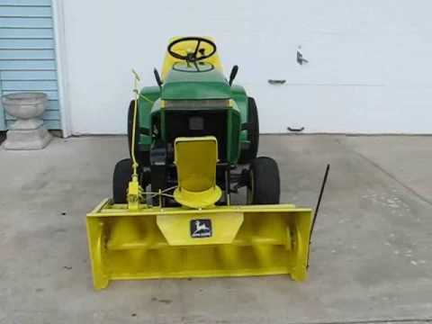
Understanding the Components of a John Deere 210
In any agricultural equipment, it is crucial to be familiar with the key mechanical elements that ensure optimal performance. Understanding how each part operates and contributes to the overall function can significantly improve maintenance and troubleshooting efforts. This section will explore the main elements that make up this robust machinery, allowing users to gain deeper insight into its workings without delving into unnecessary technical complexity.
Engine and Transmission System
The power unit and transmission work together as the heart of the machine, converting fuel into motion. The engine generates the necessary force, while the transmission ensures smooth shifting between different gears and speeds, providing the right amount of power for various tasks. Regular checks and proper care of these systems are essential to keep the equipment running efficiently.
Hydraulic and Steering Components
The hydraulic system plays a vital role in operating the machine’s lifting mechanisms. Proper fluid levels and functioning valves are critical for smooth operation. Meanwhile, the steering system ensures precise control over direction, allowing for easy maneuverability even in tight spaces. Regular inspection of these parts can prevent unexpected breakdowns and maintain a high level of performance.
How to Identify Key Tractor Parts
Understanding the essential components of your agricultural machine is crucial for maintaining its efficiency and ensuring proper operation. Recognizing each element helps with regular maintenance and replacement when necessary. This section will guide you through the process of identifying vital sections of the equipment, focusing on the main structural and functional elements.
Start by examining the central framework, as it houses many of the core mechanical systems. Pay attention to the engine area, where you will find various interconnected mechanisms that power the machine. It’s also important to check the hydraulic systems, often responsible for controlling key attachments and movement.
Don’t forget to inspect the wheels and transmission system. These parts are vital for the movement and stability of the machine. If you’re unsure of any specific piece, referencing the owner’s manual or consulting a professional can help ensure you accurately identify and assess the machinery.
Exploring the Hydraulic System Diagram

The hydraulic system is a critical component that ensures efficient operation by utilizing fluid pressure to power various mechanical functions. Understanding the flow and interaction of components within this system is essential for maintaining its functionality and identifying potential issues.
The diagram typically highlights how fluid moves through different elements, allowing users to trace connections and understand how power is distributed across various parts of the machinery. By following these connections, one can easily pinpoint any potential weak points or areas requiring maintenance.
- Pumps: These devices generate the required fluid pressure, ensuring that the hydraulic system functions smoothly.
- Valves: They regulate the direction and flow of the fluid, controlling the movement of different system components.
- Cylinders: These components convert fluid power into mechanical force, enabling the movement of various a
Maintenance Tips for Engine Components
Proper upkeep of engine elements is essential for ensuring long-lasting performance and minimizing the risk of unexpected failures. By following a few key guidelines, you can extend the lifespan of your equipment and maintain its efficiency. Regular inspections, along with timely replacements, are crucial to keeping everything running smoothly.
Regular Inspection of Key Engine Elements
Routinely check the engine for signs of wear and tear. Pay close attention to any leaks, unusual noises, or changes in performance. Early detection of issues can help prevent costly repairs and keep your equipment in optimal condition.
Lubrication and Cooling System Maintenance
Ensuring the lubrication system is functioning correctly is vital for reducing friction and preventing overheating. Regularly check fluid levels, and make sure cooling systems are clear of obstructions to maintain proper temperature control.
Gearbox and Transmission Structure Overview
The gearbox and transmission systems play a critical role in ensuring efficient power distribution within machinery. By converting energy generated from the engine into usable mechanical force, these components allow for smooth operation across various performance settings. A well-engineered transmission ensures optimal speed and torque, adapting to different conditions and tasks.
Key elements of this structure include gears, shafts, and clutches, all of which work in unison to manage power flow. Gears allow for changes in speed and direction, while shafts transfer the power between components. Clutches serve as mechanisms that engage or disengage the power transmission, offering flexibility in control.
Understanding the interrelationship of these elements is crucial for maintaining operational efficiency. Proper synchronization of the gearbox and transmission components helps to prevent wear and extend the lifespan of the machinery.
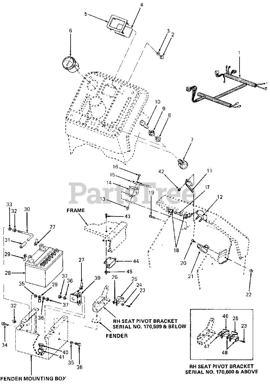
Electrical Wiring Layout for John Deere 210

This section provides an overview of the electrical system configuration, emphasizing the essential components and their connections. Understanding the wiring arrangement is crucial for troubleshooting and maintenance, ensuring optimal performance and safety of the equipment.
Key Components
The electrical system comprises several critical elements that work in harmony to ensure functionality. These include the battery, starter, ignition switch, and various connectors. Proper identification and understanding of these components are vital for effective repairs and enhancements.
Wiring Connections
The following table illustrates the primary connections within the electrical setup, outlining the function of each wire and its associated component:
Wire Color Component Function Red Battery Power supply for starting and electrical components Black Ground Completes the electrical circuit Yellow Ignition Switch Activates electrical components when turned on Green Starter Engages the engine during the starting process Blue Lights Provides illumination for operation in low light Fuel System Diagram and Common Issues
The fuel system is a crucial component in any engine, responsible for delivering the necessary fuel for efficient operation. Understanding its layout and function can help in diagnosing and resolving various problems that may arise during use. This section explores the configuration of the fuel system and highlights frequent challenges faced by users.
Typically, the system consists of several key elements, including the fuel tank, pump, filters, and injectors. Each component plays a significant role in ensuring a smooth flow of fuel to the engine. Blockages or failures within these parts can lead to performance issues, such as stalling, poor acceleration, or reduced power output.
Common problems include clogged filters, which impede fuel flow, and malfunctioning pumps that fail to maintain adequate pressure. Additionally, leaks in the fuel lines can lead to serious safety hazards and operational inefficiencies. Regular maintenance and inspections can help mitigate these issues and extend the life of the engine.
Steps to Replace Steering Mechanism Parts
Replacing the steering components of your machinery is essential for maintaining optimal performance and safety. This process involves careful planning, the right tools, and a systematic approach to ensure a successful outcome. Below are the essential steps to guide you through this task efficiently.
Preparation and Safety Measures
Before beginning the replacement, ensure you have all necessary tools and components ready. Disconnect the battery to avoid any electrical hazards. Wear safety gear, including gloves and goggles, to protect yourself from potential injuries during the procedure.
Removal and Installation
Start by detaching the existing steering assembly, taking care to document the positioning of each component for accurate reinstallation. Once removed, inspect the mechanism for any additional wear or damage. Install the new components in the reverse order of removal, ensuring everything is securely fastened and aligned correctly to restore proper functionality.
Brake System Components and Their Functions
The brake system plays a crucial role in ensuring safety and control during operation. It consists of various elements that work together to slow down or stop the vehicle effectively. Understanding these components is essential for proper maintenance and troubleshooting.
Brake Pedal: The initial point of interaction for the operator, this component converts the driver’s force into hydraulic pressure, initiating the braking process.
Master Cylinder: This vital part generates hydraulic pressure by pushing brake fluid through the system when the brake pedal is depressed, enabling the brakes to engage.
Brake Lines: These conduits transport brake fluid from the master cylinder to the brake calipers or wheel cylinders, ensuring efficient pressure transmission throughout the system.
Brake Calipers: Located at each wheel, these components house the brake pads and apply pressure to them when hydraulic fluid is delivered, creating friction against the brake disc or drum.
Brake Pads: These friction materials are pressed against the brake discs to slow down or halt the vehicle. They are designed to withstand high temperatures and wear over time.
Brake Discs/Drums: These rotating components provide the surface against which the brake pads or shoes press, converting kinetic energy into thermal energy through friction.
Brake Fluid: A specialized hydraulic fluid that transfers force from the brake pedal to the braking mechanism, ensuring responsiveness and reliability during operation.
Anti-lock Braking System (ABS): This advanced feature prevents wheel lock-up during hard braking, enhancing vehicle control and stability. It uses sensors and a control module to modulate brake pressure as needed.
Each of these components plays a significant role in the overall functionality of the braking system. Regular inspection and maintenance of these parts are essential for optimal performance and safety.