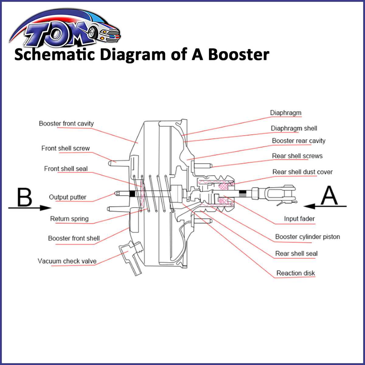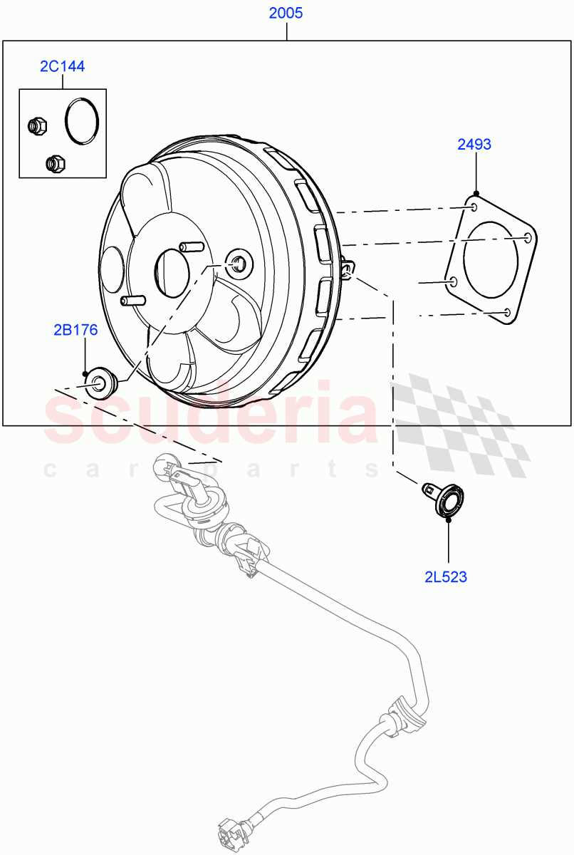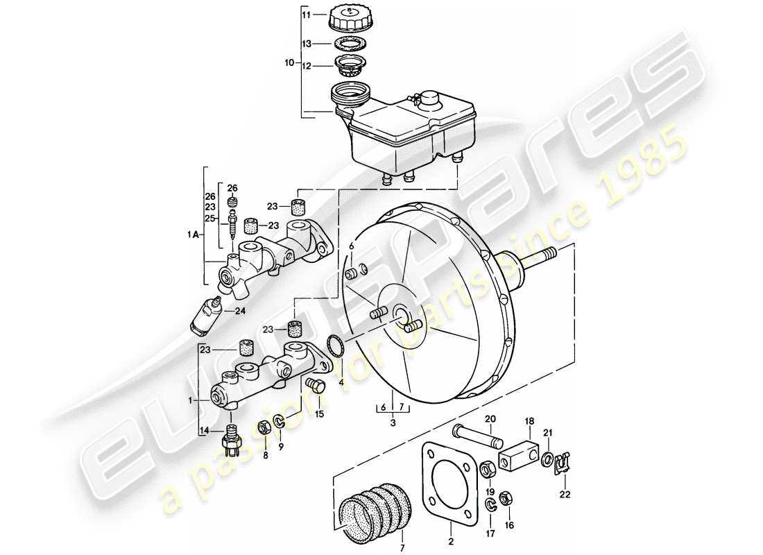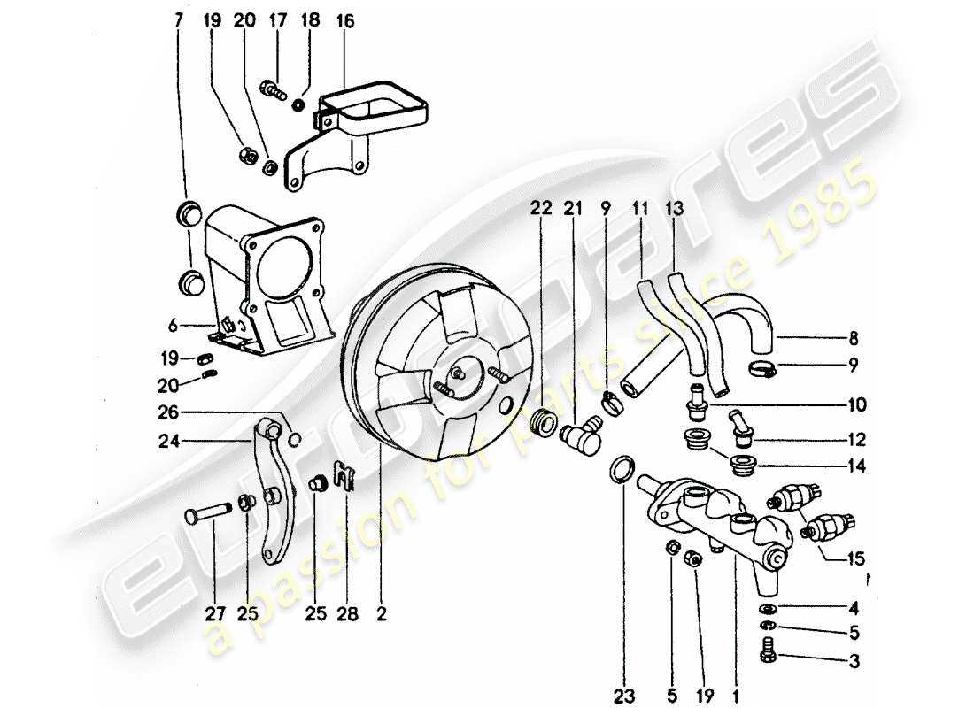
Understanding the various elements that contribute to the functionality of a hydraulic amplification system is essential for maintaining optimal vehicle performance. This system plays a crucial role in enhancing the effectiveness of the actuation process, allowing for smoother operation and increased safety. A detailed exploration of these components reveals their intricate interactions and how they work together to achieve the desired outcomes.
Each component within this assembly serves a specific purpose, contributing to the overall efficiency and reliability of the mechanism. Identifying these elements and their respective functions is vital for diagnosing issues and performing effective repairs. A thorough knowledge of how these pieces fit together will aid in comprehending the complete operational structure.
In addition, recognizing the materials and construction methods used in these components can provide insights into their durability and performance characteristics. As we delve into this subject, it becomes apparent that understanding the complete assembly is not only beneficial for mechanics but also for anyone interested in automotive technology and maintenance.
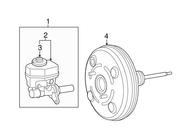
In vehicles, certain components work together to enhance the performance of a vital control system. One such mechanism uses the energy from engine operation to assist with force application, improving the overall response. This process reduces the physical effort required from the user, offering smoother and more efficient operation.
Main Structure and Key Elements
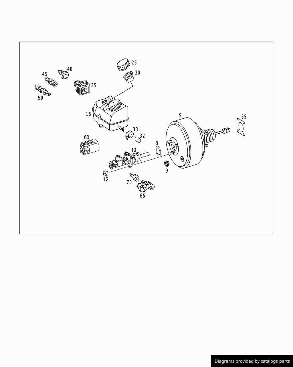
The primary system is made up of several interconnected parts. Each part plays a specific role in making sure the system operates smoothly. These elements work in harmony to manage the transfer of energy, ensuring proper coordination during use.
| Component | Function | |
|---|---|---|
| Vacuum Source | Provides necessary power for the system | |
| Input Valve | Regulates the flow of energy |
| Issue | Description | Symptoms |
|---|---|---|
| Air Leaks | Air infiltration into the system can diminish effectiveness, causing sluggish performance. | Soft or spongy pedal feel, extended stopping distances. |
| Fluid Contamination | Debris or moisture in hydraulic fluid can lead to internal damage and decreased efficiency. | Inconsistent pedal response, unusual noises when applying pressure. |
| Wear and Tear | Components can deteriorate over time due to repeated use, affecting overall functionality. | Unresponsive or overly sensitive braking, requiring excessive force. |
| Vacuum Failure | Insufficient vacuum supply can prevent proper assistance, leading to harder pedal effort. | Pedal feels hard, and increased force is needed to stop the vehicle. |
Importance of Maintenance and Care
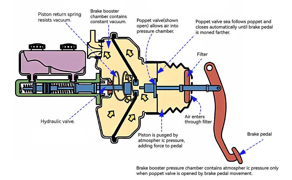
Regular upkeep and attention to vehicle components play a crucial role in ensuring optimal performance and longevity. Proper care helps prevent unexpected failures, enhances safety, and promotes efficient operation. By prioritizing maintenance, vehicle owners can enjoy a smoother driving experience and minimize the risk of costly repairs down the line.
Benefits of Routine Care
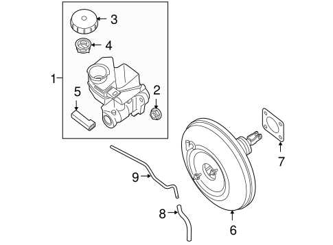
- Increased Safety: Well-maintained components reduce the likelihood of malfunctions that can lead to accidents.
- Enhanced Performance: Regular checks ensure that systems operate smoothly, contributing to better handling and responsiveness.
- Cost Savings: Preventive maintenance often costs less than addressing problems after they arise.
- Improved Resale Value: A well-maintained vehicle tends to retain its value better, making it more appealing to potential buyers.
Key Maintenance Practices
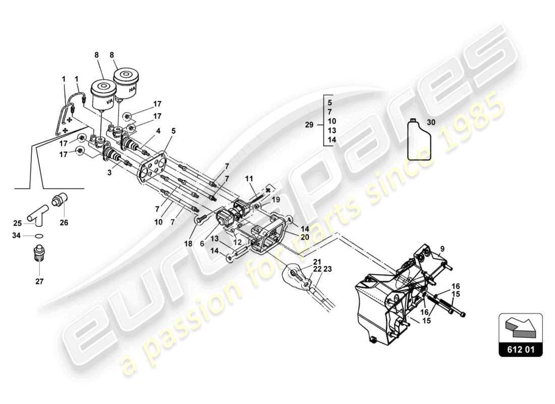
- Regular Inspections: Periodically check essential systems to identify any signs of wear or damage.
- Fluid Changes: Ensure that all fluids are changed as recommended to keep systems functioning efficiently.
- Replace Worn Components: Address any parts showing signs of wear promptly to prevent further issues.
- Follow Manufacturer Guidelines: Adhering to the manufacturer’s recommendations for maintenance can significantly extend the life of your vehicle.
How to Identify Brake Booster Problems
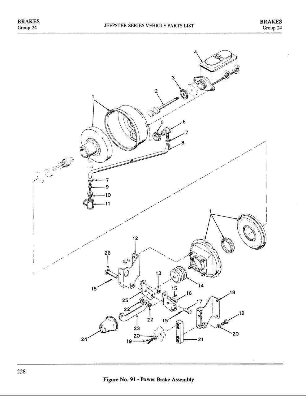
Understanding the signs of issues within the hydraulic assist system can enhance vehicle safety and performance. A thorough examination of specific symptoms can reveal potential malfunctions, leading to necessary repairs or replacements.
Below are common indicators that suggest there may be a malfunction within the hydraulic assist mechanism:
| Symptoms | Possible Causes |
|---|---|
| Hard Pedal Response | Vacuum Leak or Internal Failure |
| Increased Stopping Distance | Insufficient Pressure or Fluid Leakage |
| Hissing Noise When Pressing Pedal | Air Leak in the System |
| Pedal Sinks to the Floor | Fluid Leak or Internal Damage |
Being aware of these signs and conducting regular inspections can help maintain optimal functionality and ensure safe driving conditions.
Replacement Parts for Brake Boosters
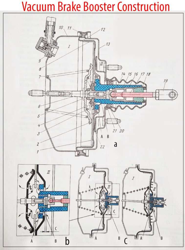
When maintaining the performance of a vehicle’s stopping system, it is crucial to consider the various components that contribute to its efficiency. Over time, certain elements may wear out or become less effective, necessitating replacement to ensure optimal functionality and safety. This section will explore the key components that can be replaced to enhance the effectiveness of this vital system.
| Component | Description | Function |
|---|---|---|
| Vacuum Chamber | A sealed container that uses atmospheric pressure to assist in stopping. | Helps amplify the force applied to the braking mechanism. |
| Diaphragm | A flexible membrane that separates the vacuum chamber from the atmosphere. | Enables the transfer of pressure changes to assist in braking power. |
| Check Valve | A one-way valve that prevents backflow of air into the vacuum chamber. | Maintains the necessary pressure for effective operation. |
| Mounting Bracket | A structural element used to secure the assembly to the vehicle. | Provides stability and proper alignment during operation. |
| Piston | A cylindrical component that moves within the chamber. | Translates the applied force into hydraulic pressure for stopping. |
Comparing Different Brake Booster Types
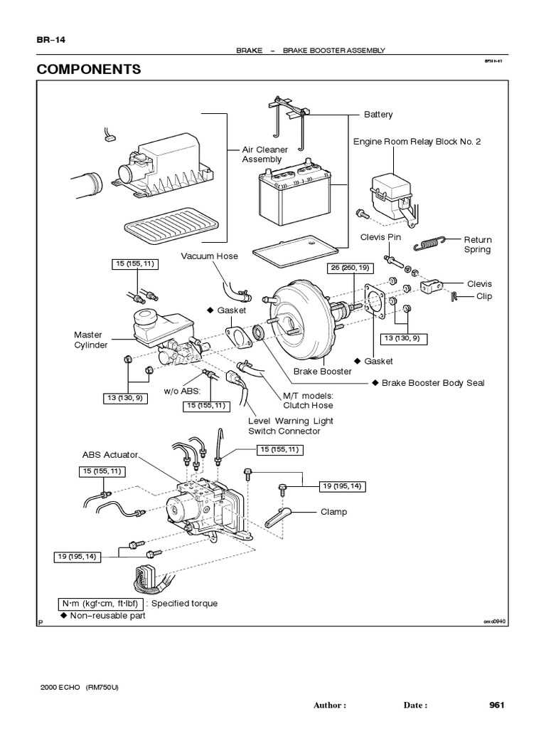
Understanding the various assistance mechanisms in vehicle stopping systems is essential for optimizing performance and safety. Each type of enhancement system offers distinct characteristics, advantages, and applications, impacting overall driving experience. This section explores the primary variations, providing insights into their unique functions and operational mechanisms.
Types of Assistance Mechanisms
- Vacuum-Operated Systems:
- Utilize engine vacuum to amplify force.
- Common in traditional vehicles.
- Efficient for moderate stopping power.
- Hydraulic-Assist Mechanisms:
- Use hydraulic fluid pressure for force enhancement.
- Ideal for high-performance applications.
- Provide rapid response and stronger stopping capability.
- Electronic Systems:
- Incorporate electronic controls to manage force application.
- Allow for adjustable responsiveness based on driving conditions.
- Increasingly popular in modern vehicles.
Choosing the Right System
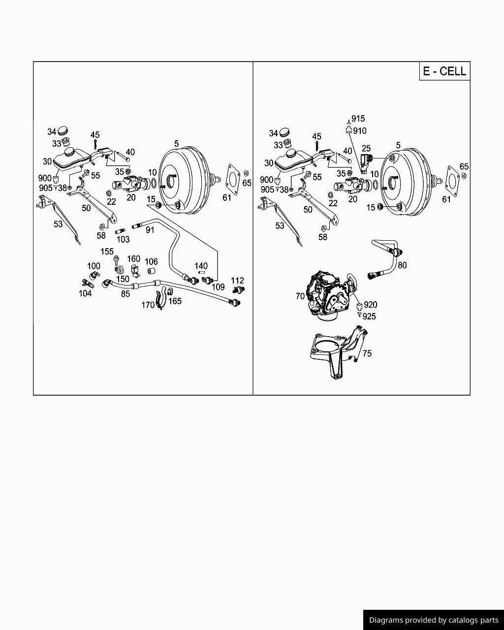
Selecting the appropriate enhancement mechanism involves considering various factors, including vehicle type, intended use, and performance requirements. Evaluating these elements ensures optimal function and safety in diverse driving scenarios.
- Evaluate driving conditions and environments.
- Consider vehicle weight and braking demands.
- Assess personal driving style and preferences.
