In the realm of machinery maintenance and repair, comprehending the arrangement and functionality of various elements is crucial. A well-structured layout not only enhances the efficiency of the equipment but also aids in identifying potential issues during routine inspections. This section delves into the intricacies of the essential components found in a specific machine model, providing insights into their relationships and overall design.
Familiarity with the structure of these mechanisms can significantly benefit users and technicians alike. By grasping how individual parts interact, one can facilitate smoother operations and effective troubleshooting. This exploration serves as a guide to navigating the complex assembly, allowing for better maintenance practices and a deeper understanding of the machinery’s capabilities.
Equipped with this knowledge, operators can make informed decisions regarding repairs and upgrades, ultimately prolonging the lifespan of the equipment. Embracing the details of the assembly leads to more efficient usage and an enhanced experience for those who rely on these powerful tools in their daily tasks.
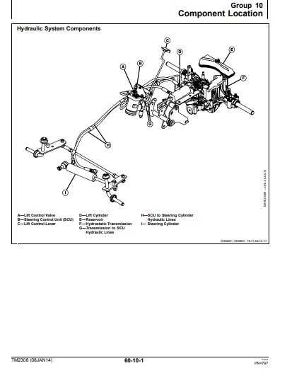 tags and avoids repetition of phrases or words. Overview of John Deere 737 Model”>
This section will provide a comprehensive overview of a particular model, focusing on its design and functionality. By exploring the key components and their roles, readers can gain a deeper understanding of the machinery’s operation and maintenance.
1. Key Components of the Equipment
Understanding the essential elements is crucial for effective operation. Each part contributes to the overall performance and reliability of the machine.
2. Maintenance Guidelines
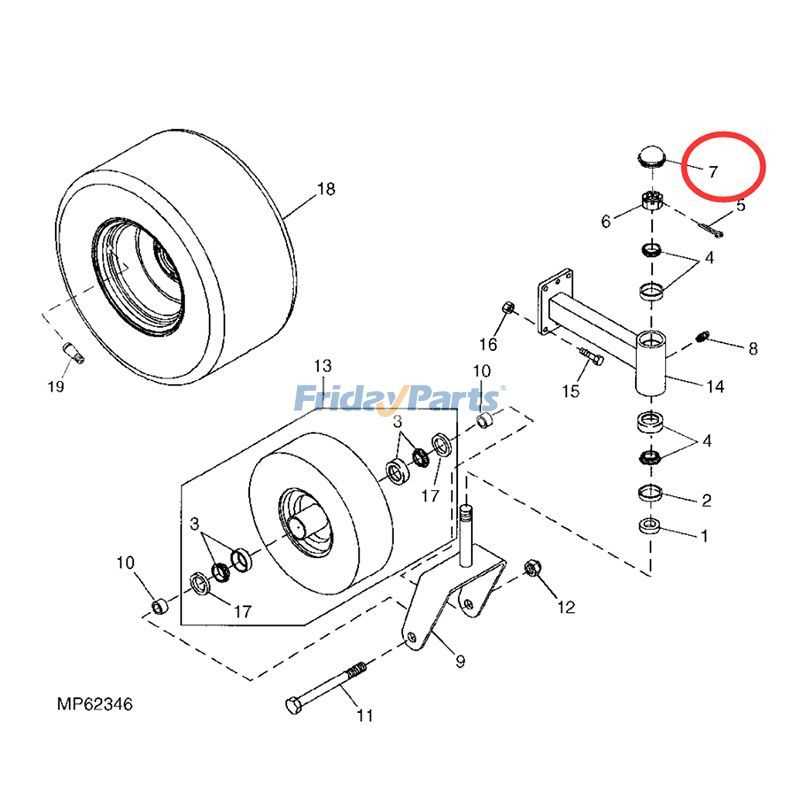
Regular upkeep ensures longevity and efficiency. Following recommended practices can help prevent common issues and extend the lifespan of the equipment.
3. Troubleshooting Common Issues
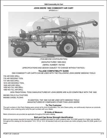
Identifying frequent problems can save time and resources. Knowing how to address these concerns enhances operational efficiency.
4. Accessory Options
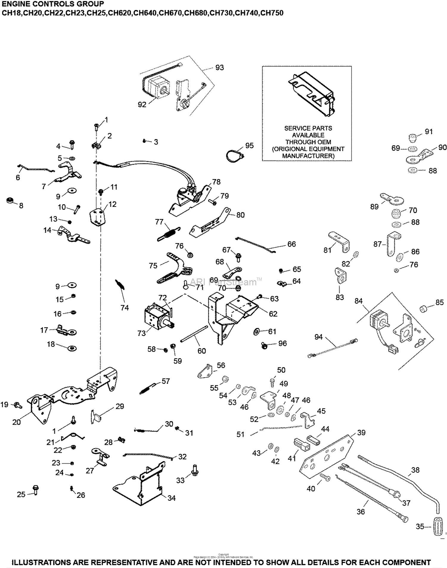
Additional tools can improve functionality and versatility. Exploring available enhancements allows users to customize their experience.
5. Safety Considerations
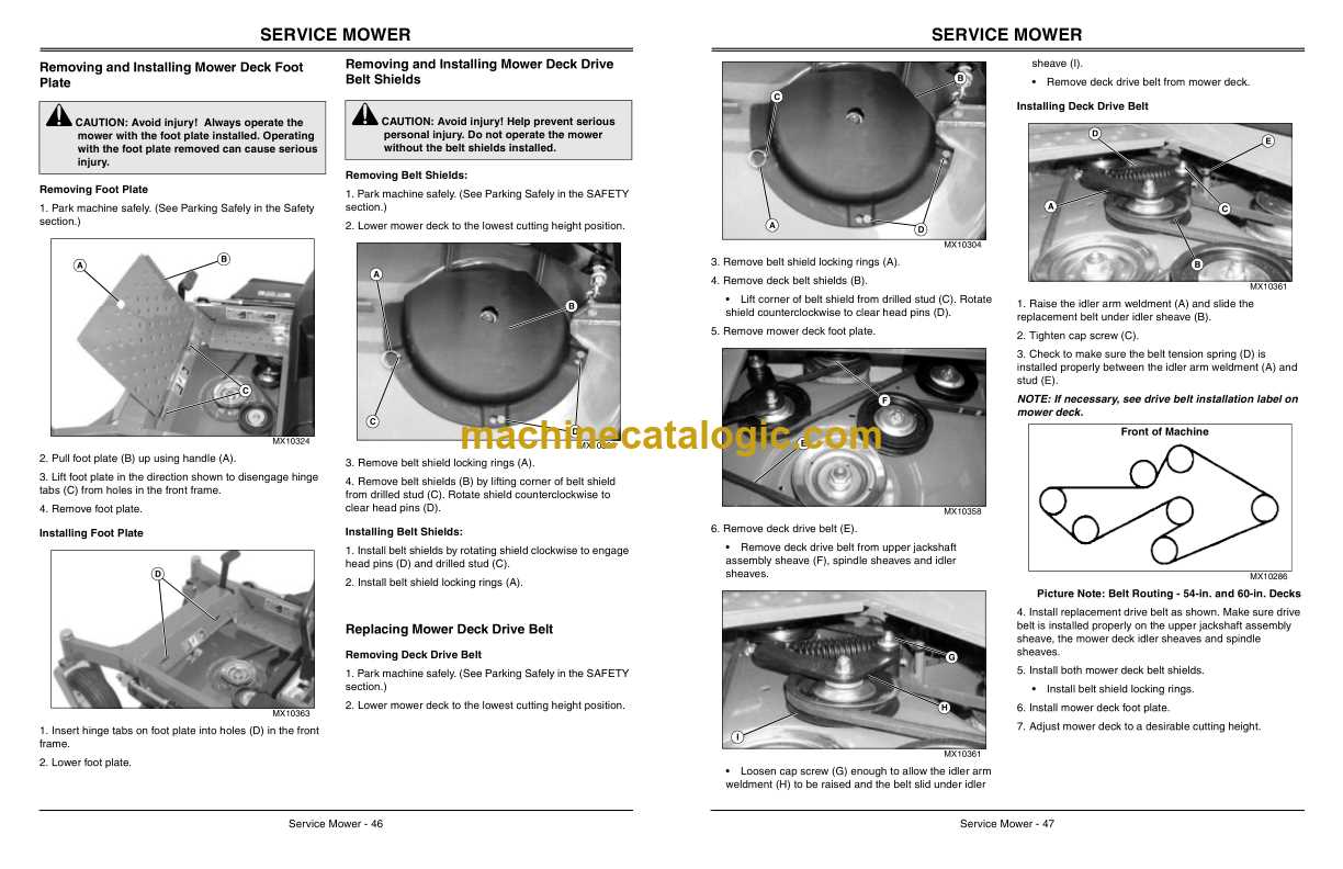
Prioritizing safety is essential when operating any machinery. Awareness of potential hazards and following safety protocols can minimize risks.
6. Comparison with Similar Models
Examining other machinery can provide insights into performance and features. This comparison aids in making informed decisions regarding purchases.
7. Expert Tips for Optimal Use
Advice from experienced users can lead to better results. Implementing best practices enhances both efficiency and effectiveness.
8. Future Developments
Keeping abreast of advancements in technology can inform decisions regarding upgrades. Anticipating changes can help users stay ahead in their operations.
| Component | Description | Importance |
|---|---|---|
| Engine | Power source for operation | Essential for functionality |
| Transmission | Transfers power to wheels | Critical for mobility |
| Hydraulic System | Controls lifting and lowering | Vital for maneuverability |
| Chassis | Structural framework | Provides stability |
Key Components and Their Functions
The intricate design of agricultural machinery relies heavily on various essential elements that contribute to its overall performance and efficiency. Understanding these fundamental components provides valuable insights into how each part works in harmony to ensure smooth operation and longevity.
Engine: The heart of the machine, the engine converts fuel into mechanical energy, driving the entire system. Its performance directly impacts productivity and operational capabilities.
Transmission: This component transmits power from the engine to the wheels, allowing for smooth acceleration and deceleration. It plays a crucial role in adapting to different terrains and conditions.
Hydraulic System: Utilizing fluid power, the hydraulic system controls various functions such as lifting and lowering attachments. It enhances the versatility of the machinery, enabling it to perform multiple tasks effectively.
Chassis: The framework supports all other components and provides stability. A robust chassis ensures durability and resilience against the rigors of fieldwork.
Control System: This system includes various levers and switches that allow the operator to manage different functions easily. A well-designed control system enhances user experience and operational precision.
In summary, the effectiveness of agricultural machinery stems from the synergy of these vital components, each fulfilling its specific role to achieve optimal functionality.
Understanding the Parts Diagram
Grasping the layout of components is essential for effective maintenance and repair of machinery. A well-structured visual representation helps users identify individual elements, their functions, and interconnections. This section aims to provide clarity on how to interpret such visual guides.
Importance of Component Identification
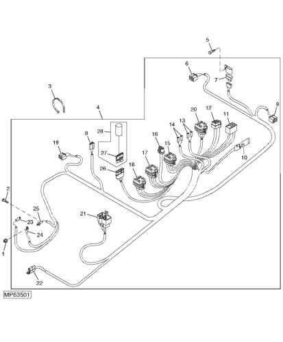
Recognizing each component’s role is vital for ensuring proper operation. The following points highlight the significance:
- Facilitates quick troubleshooting of issues.
- Enhances the ability to perform repairs efficiently.
- Promotes understanding of how various elements interact.
Key Features to Look For
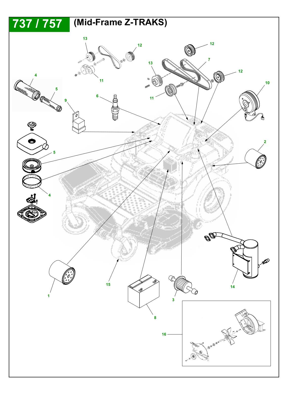
When analyzing a visual representation, focus on these essential features:
- Clear labeling of each element.
- Logical organization that groups related components.
- Indicators for directional flow and connections.
By familiarizing oneself with these aspects, users can navigate the visual representation with confidence, leading to better maintenance practices.
Common Issues and Solutions
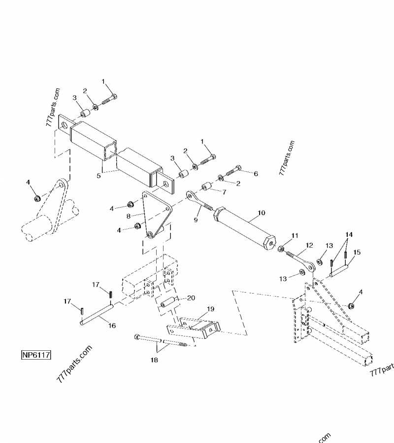
When operating machinery, various challenges may arise that can affect efficiency and performance. Understanding these frequent problems and their corresponding solutions can significantly enhance operational effectiveness and prolong the lifespan of the equipment.
Frequent Challenges
- Engine performance issues
- Hydraulic system malfunctions
- Electrical component failures
- Transmission difficulties
Effective Solutions
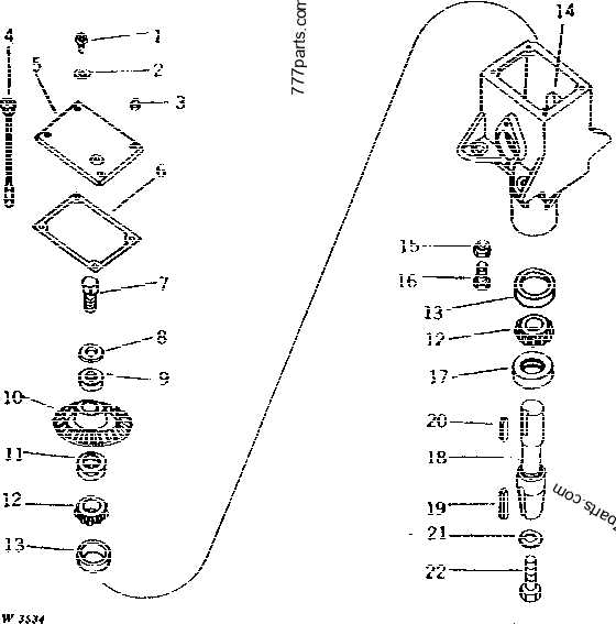
- Regular maintenance checks to ensure all systems are functioning correctly.
- Inspect and replace worn-out belts and hoses as needed.
- Check fluid levels and quality to maintain optimal performance.
- Utilize diagnostic tools to identify and address electrical issues promptly.
By implementing these solutions and maintaining a proactive approach, operators can effectively manage common challenges, ensuring smoother operation and reducing downtime.
Maintenance Tips for Longevity
Ensuring the durability and efficiency of your equipment requires regular attention and care. Implementing best practices can significantly extend its operational life and enhance performance. This section outlines essential maintenance strategies to help you achieve optimal functionality.
One crucial aspect of upkeep involves timely inspections and routine servicing. By identifying potential issues early, you can prevent costly repairs and extend the lifespan of your machinery. Below is a table outlining key maintenance tasks along with recommended intervals:
| Maintenance Task | Recommended Interval |
|---|---|
| Oil Change | Every 50 hours of operation |
| Air Filter Cleaning/Replacement | Every 100 hours of operation |
| Blade Sharpening | Every 25 hours of use |
| Check Tire Pressure | Monthly |
| Battery Inspection | Every 6 months |
Additionally, using high-quality lubricants and fuels can contribute to smoother operation and reduce wear and tear. Storing your equipment in a sheltered environment during off-seasons also plays a vital role in maintaining its condition.
Replacement Parts Availability
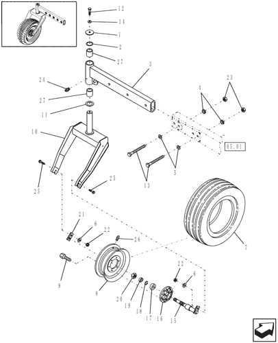
Ensuring that essential components are accessible is crucial for maintaining optimal performance and longevity of machinery. Availability of replacement elements can significantly impact operational efficiency, reducing downtime and enhancing productivity.
When considering the procurement of substitute components, several factors should be taken into account:
- Quality: It is vital to source high-quality alternatives that meet or exceed original specifications.
- Compatibility: Ensure that the replacements are designed to fit seamlessly with existing systems.
- Supply Chain: Evaluate the reliability of suppliers and their ability to deliver on time.
- Cost: Compare prices among various vendors to find competitive offers without compromising quality.
Several resources can assist in locating suitable replacements:
- Authorized Dealers: They typically offer a wide range of components tailored for specific models.
- Online Marketplaces: Various e-commerce platforms provide access to a vast selection of aftermarket options.
- Local Distributors: Regional suppliers may have readily available stock, reducing shipping times.
By considering these factors and utilizing available resources, one can ensure a steady supply of necessary components, contributing to sustained functionality and efficiency.
How to Read the Diagram
Understanding a schematic representation is essential for effective maintenance and repairs. These visual aids provide critical information regarding components and their interconnections, enabling users to identify and troubleshoot issues efficiently. Familiarizing oneself with the layout and symbols used can significantly enhance comprehension and usability.
Identifying Key Components
Start by familiarizing yourself with the main elements presented in the illustration. Each component is usually represented by a unique symbol or label. Recognizing these symbols is crucial, as they serve as a guide to understanding the function and location of various parts within the system.
Interpreting Connections and Flow
Next, pay attention to the lines and arrows that depict connections and pathways between components. These indicators illustrate how different elements interact and the flow of operation within the machinery. Understanding these relationships is vital for troubleshooting and ensuring everything operates smoothly.
Importance of Regular Inspections
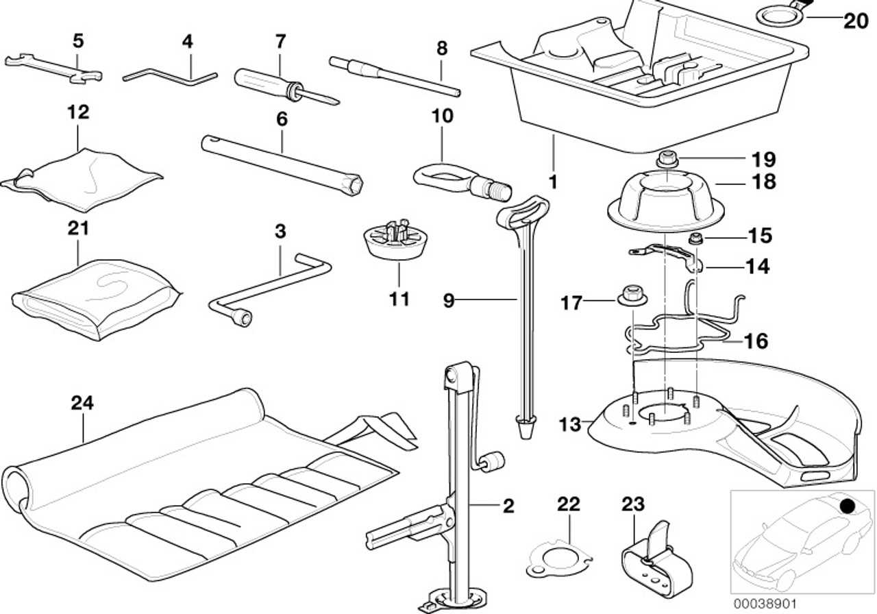
Conducting routine evaluations of equipment is essential for ensuring optimal functionality and longevity. These assessments help identify potential issues before they escalate into significant problems, ultimately saving time and resources. Regular inspections foster a proactive approach to maintenance, allowing for timely interventions that enhance overall performance.
Benefits of Consistent Evaluations
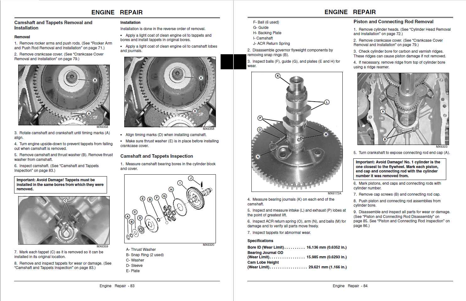
- Early detection of wear and tear, preventing breakdowns.
- Improved safety for operators and bystanders.
- Increased efficiency and productivity of machinery.
- Extended lifespan of equipment through proper care.
Recommended Inspection Practices
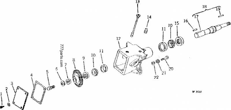
- Schedule regular checks based on usage frequency.
- Utilize checklists to ensure thorough evaluations.
- Engage qualified personnel for complex assessments.
- Document findings to track performance over time.