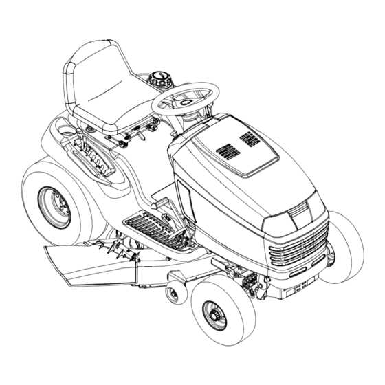
Control Panel: The interface that allows the operator to adjust settings and monitor the machine’s status, enhancing user experience and over
Steering Mechanism Overview
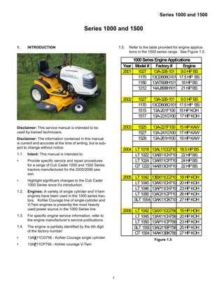
The steering system is a critical component in ensuring precise control and maneuverability of the machine. It plays a significant role in guiding the direction of movement, allowing for smooth turns and responsive handling. This section provides a comprehensive examination of the steering elements, highlighting their functions and interactions.
Key Components of the Steering Assembly
The primary components within the steering assembly include various interconnected parts that work together to translate the operator’s input into directional control. Each element, from the steering wheel linkage to the mechanical joints, has a specific purpose in maintaining the stability and accuracy of navigation.
Functionality and Interaction
The effectiveness of the steering setup relies on the synchronization between its individual parts. The seamless interaction between the linkages, shafts, and pivot points ensures that the operator can make quick adjustments with minimal effort, enhancing both the precision and the ease of control.
| Component |
Function |
Location |
| Steering Linkage |
Transmits motion from the steering wheel to the front wheels |
Between the steering wheel and the front axle |
| Control Arm |
Supports the wheels and allows vertical motion for smooth handling |
Attached to the front suspension |
| Pitman Arm |
Converts the rotary motion of the steering into linear motion |
Connected to the steering box |
Essential Parts and Their Functions
Understanding the various components that make up a mechanical system is crucial for ensuring its efficiency and longevity. This section highlights the core elements involved, focusing on their specific roles and how they contribute to the overall performance.
Key Mechanical Elements
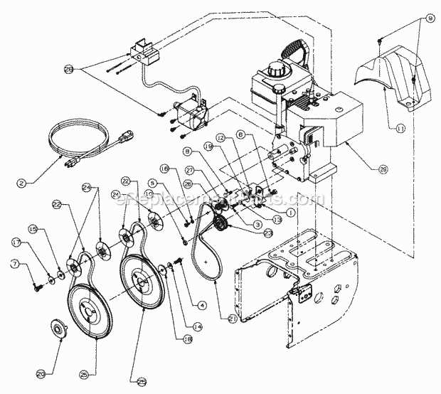
- Drive System: This section is responsible for transferring power from the engine to the wheels, ensuring smooth motion and control.
- Steering Mechanism: Provides precise control over the movement, allowing for easy navigation and direction changes.
- Cutting Assembly: A crucial unit designed to handle trimming operations, ensuring clean and even results.
Additional Functional Components
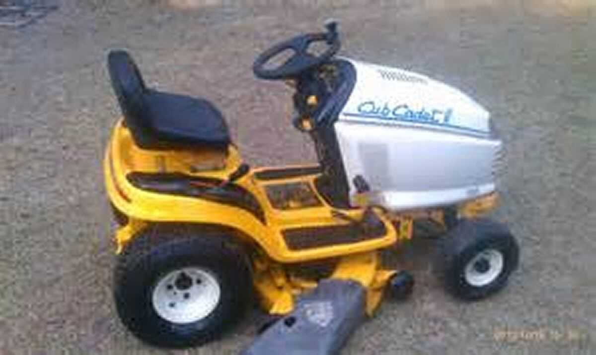
- Engine Unit: The heart of the setup, generating the necessary energy to power all other functions.
- Cooling System: Maintains optimal temperatures to prevent overheating, enhancing the lifespan of the machinery.
- Safety Controls: Includes multiple features that ensure safe operation and protect both the user and the equipment.
Cutting Deck Assembly Guide
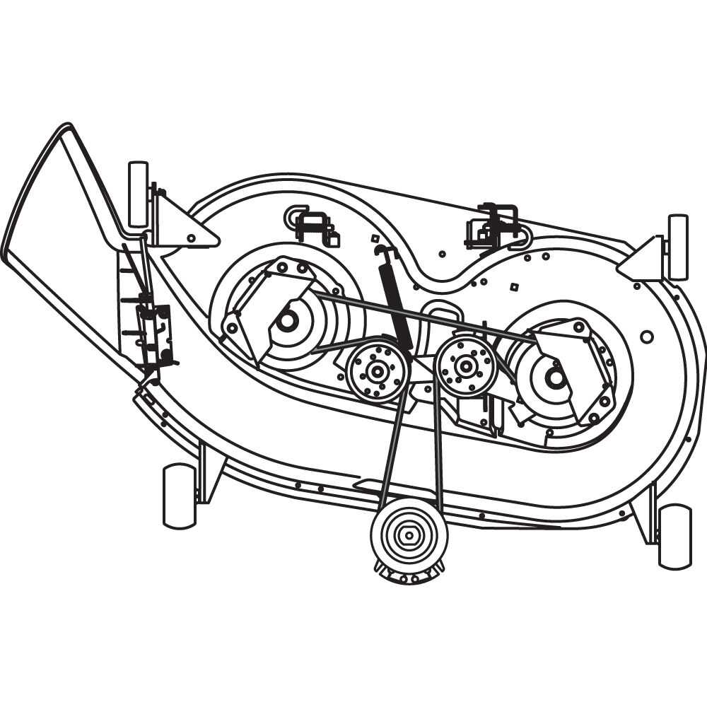
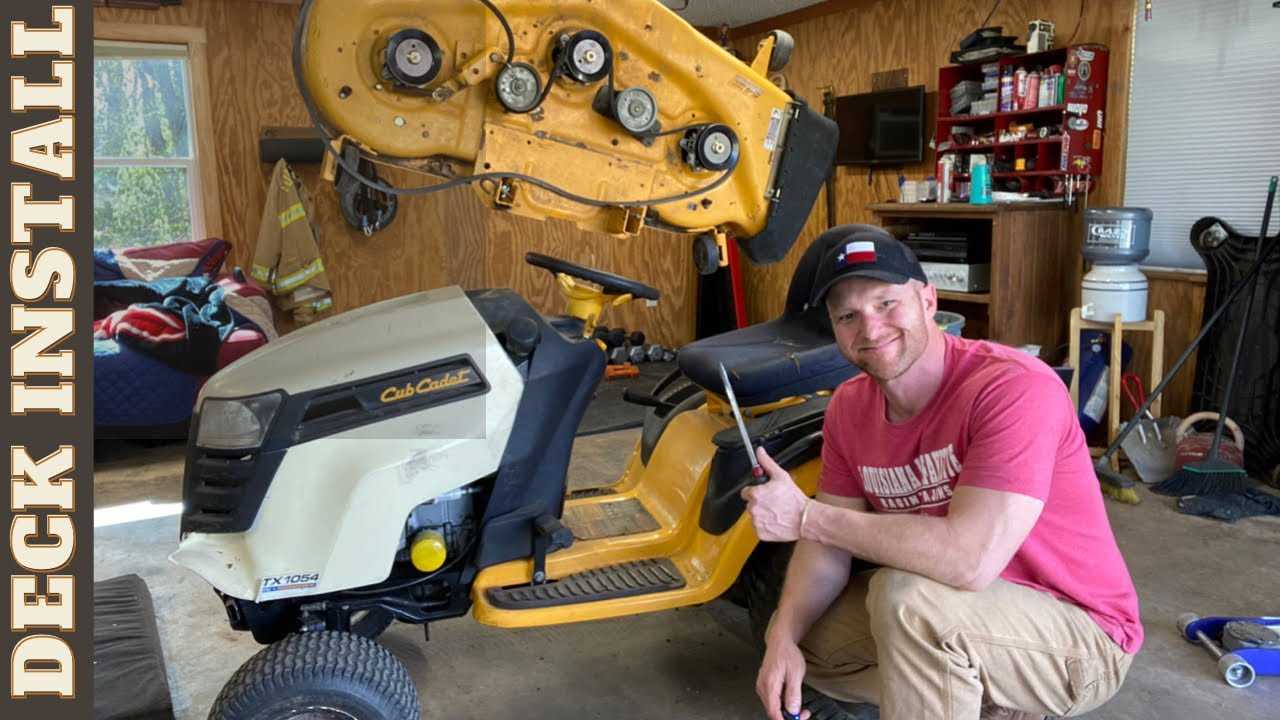
This section provides essential instructions for assembling the mowing platform, which is a crucial component of the equipment. A well-assembled deck ensures optimal performance and longevity, allowing for effective grass cutting and overall maintenance.
Begin by gathering all necessary components, including blades, brackets, and bolts. Ensure that your workspace is clean and organized to facilitate the assembly process. Before proceeding, consult the manufacturer’s manual for any specific recommendations or safety guidelines that should be followed.
Start by attaching the support brackets to the main frame. Secure them tightly using the provided bolts, ensuring that they are aligned properly. Next, install the cutting blades, taking care to orient them correctly for effective operation. Use protective gloves during this step to avoid injury.
Once the blades are installed, connect the belt to the pulleys, ensuring it has the appropriate tension. This is vital for the power transfer from the engine to the deck. After completing the assembly, conduct a thorough inspection to confirm that all parts are secured and functioning correctly.
Finally, perform a test run to ensure that the mowing platform operates smoothly without any unusual noises or vibrations. Regular maintenance and inspections will help maintain the efficiency and safety of the assembly.
How the Pieces Fit Together
Understanding the assembly of various components is crucial for optimal functionality. Each element plays a specific role, and their arrangement significantly impacts the overall performance of the machine. By examining how these components interconnect, one can gain insights into their operation and maintenance.
Initially, it is essential to identify the primary sections involved. These include structural frameworks, driving mechanisms, and operational tools, all designed to work in unison. Each section is tailored to fit securely with its counterparts, ensuring stability and efficiency during use.
Interconnections between elements often rely on precision fittings, which are designed to accommodate slight variations in alignment. This precision ensures that each part performs its function without undue stress or wear. Understanding these interconnections can facilitate easier repairs and modifications in the future.
In summary, recognizing how these components fit together provides valuable knowledge for both operation and troubleshooting. A well-informed user can make adjustments and enhancements, leading to improved performance and longevity of the machinery.
Electrical System Analysis

The analysis of the electrical system within a gardening machine is essential for ensuring optimal performance and longevity. This examination involves understanding the various components that contribute to the machine’s electrical functionality, allowing for efficient troubleshooting and maintenance.
Key Components: The core elements include the battery, wiring harness, ignition system, and various switches. Each of these parts plays a critical role in the overall functionality, influencing how power is distributed and managed throughout the unit.
Power Distribution: An effective distribution of electrical energy is crucial for seamless operation. Identifying any faults in the connections can prevent unexpected failures and enhance the reliability of the equipment.
Routine Inspections: Regular checks and maintenance of the electrical components help in identifying wear and potential issues before they escalate. This proactive approach can save time and resources, ensuring that the machine remains in optimal working condition.
In conclusion, a thorough understanding of the electrical network within a gardening machine not only improves its efficiency but also extends its lifespan. Taking the time to analyze and maintain these systems is a worthwhile investment for any user.
Identifying Key Wiring Parts
Understanding the essential components of a wiring system is crucial for effective maintenance and troubleshooting. This section focuses on recognizing the main elements that ensure proper functionality and safety within the electrical framework.
Connectors play a vital role in linking various wires and facilitating communication between different parts. Identifying the types and configurations of these connectors can help in achieving seamless connectivity.
Another important element is the wiring harness, which organizes and protects the individual wires, preventing damage from external factors. A thorough examination of the harness layout is essential for identifying any potential issues.
Furthermore, fuses are critical safety devices that protect the electrical system from overloads. Understanding their locations and ratings will aid in maintaining the integrity of the system.
Lastly, attention to grounding points is necessary to ensure that the electrical components function safely and effectively. Proper identification and maintenance of these points can prevent electrical failures and enhance the overall reliability of the system.
