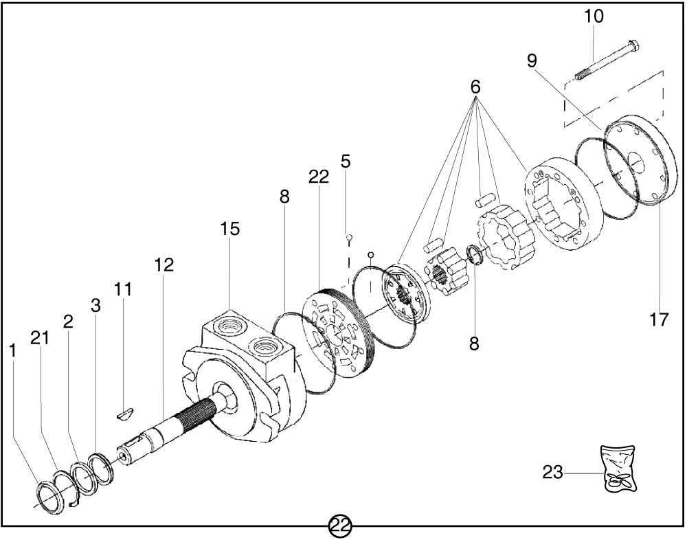
The intricacies of hydraulic systems are often overlooked, yet they play a crucial role in various machinery and vehicles. A comprehensive grasp of these systems requires an examination of their fundamental elements, each contributing to the overall functionality. This article delves into the essential components that make up these dynamic systems, shedding light on their arrangement and interconnection.
As we explore the layout of these integral pieces, it becomes evident how each element interacts to deliver power and efficiency. Whether it’s the driving force behind a vehicle or the mechanism that enhances performance in heavy equipment, understanding these components is vital for troubleshooting and maintenance. By gaining insights into their structure, one can appreciate the engineering prowess that enables smooth operation.
In this section, we will provide a visual representation that highlights the specific roles and positions of these components within the system. Such an overview not only simplifies the complexity but also enhances the knowledge required for effective handling and repairs. Emphasizing clarity and precision, we aim to equip readers with the tools needed for a deeper understanding of hydraulic systems.
Parker Wheel Motor Overview
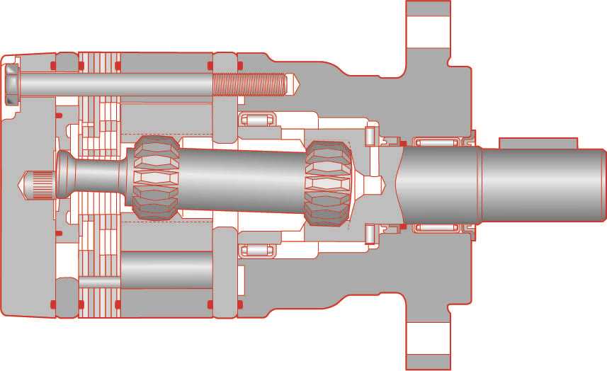
This section provides an insight into a specific type of hydraulic drive system designed for enhanced performance in various applications. It showcases the functionality, advantages, and components that contribute to its effectiveness.
Key Features
- High efficiency in power transmission
- Compact design suitable for limited spaces
- Robust construction for durability
Applications
- Agricultural machinery
- Construction equipment
- Material handling systems
Understanding the intricacies of this system is essential for optimizing its use in various industries.
Key Components of Wheel Motors
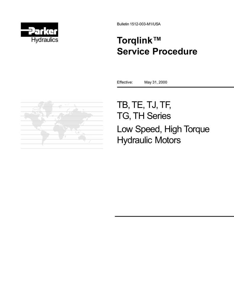
Understanding the essential elements of rotational drive systems is crucial for optimizing their performance and reliability. These systems are composed of various integral components, each playing a vital role in ensuring efficient operation and durability.
Main Elements
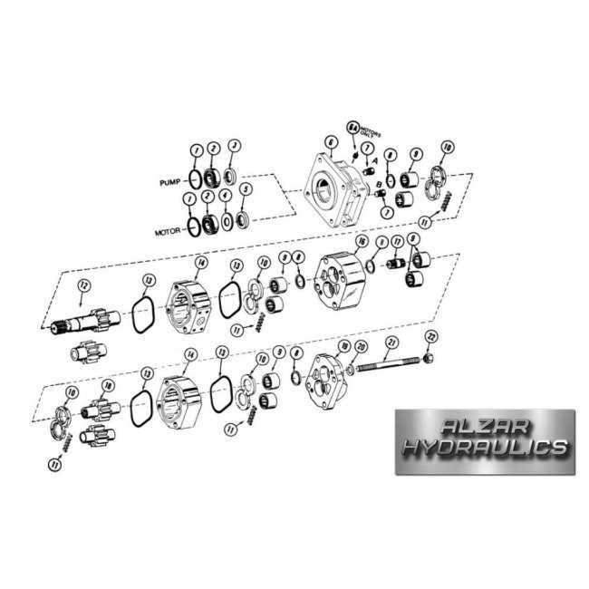
The core components include a propulsion mechanism, a housing structure, and a connection interface. Each of these parts must work in harmony to facilitate smooth movement and transfer of power.
Functionality Overview
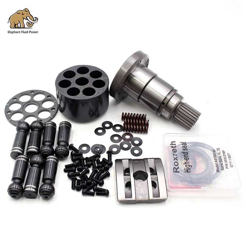
| Component | Function |
|---|---|
| Propulsion Unit | Generates the necessary force for movement. |
| Housing | Protects internal components and maintains structural integrity. |
| Interface | Connects the system to the vehicle, ensuring power transfer. |
By examining these fundamental components, one can appreciate the intricacies involved in the design and functionality of these advanced systems.
Understanding Motor Functionality
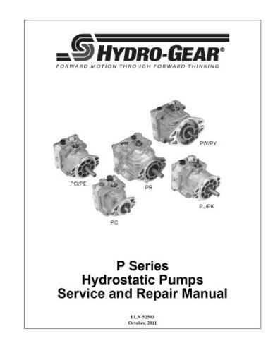
The operation of a mechanical device relies on the interaction of various components that work in harmony to achieve desired outcomes. Grasping how these elements function together is essential for effective usage and troubleshooting.
Key concepts include:
- Energy Conversion: Transforming one form of energy into another.
- Torque Generation: The force that causes rotation.
- Efficiency: Maximizing output while minimizing energy loss.
To explore these ideas further, consider the following:
- Components play distinct roles, contributing to overall performance.
- Understanding mechanical advantage is crucial for design optimization.
- Regular maintenance ensures longevity and functionality.
By delving into these principles, one can appreciate the ultimate significance of each element in enhancing operational effectiveness.
Importance of Proper Maintenance
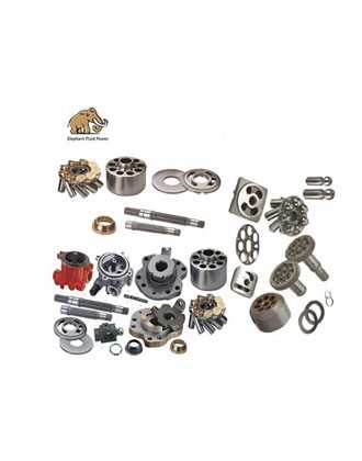
Ensuring the longevity and efficiency of machinery relies heavily on consistent upkeep. Neglecting routine care can lead to decreased performance, unexpected failures, and costly repairs.
Regular inspection of components plays a crucial role in identifying potential issues before they escalate. This proactive approach not only enhances operational reliability but also extends the lifespan of the equipment.
Furthermore, scheduled maintenance minimizes downtime, allowing for smoother operations and improved productivity. A well-maintained system contributes to overall safety, reducing the risk of accidents and injuries in the workplace.
Common Issues in Wheel Motors
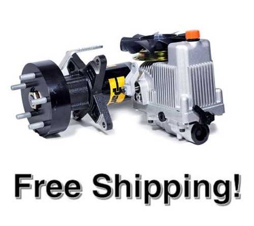
In the realm of powered propulsion systems, various challenges can arise that affect performance and reliability. Understanding these common obstacles is essential for maintaining optimal functionality and ensuring longevity in operation. Here, we explore prevalent concerns encountered in such mechanisms, offering insights into their implications and potential solutions.
1. Overheating
Excessive heat can lead to severe damage. Factors contributing to this issue include:
- Insufficient cooling systems
- Inadequate lubrication
- High operational loads
Regular monitoring and implementing cooling solutions can mitigate overheating risks.
2. Leakage
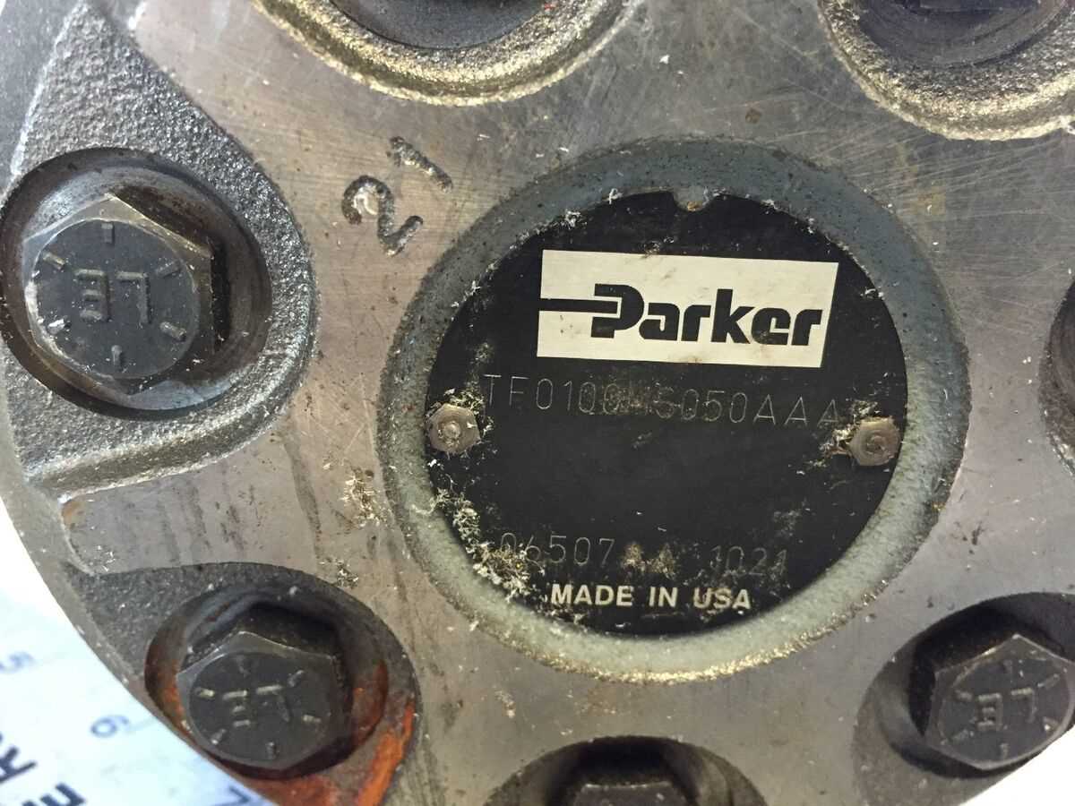
Fluid leakage is a significant problem that can compromise efficiency. Common causes include:
- Worn seals and gaskets
- Improper assembly
- Corrosion of components
Routine inspections and timely replacements of worn elements are crucial to prevent fluid loss.
Parts Replacement and Upgrades
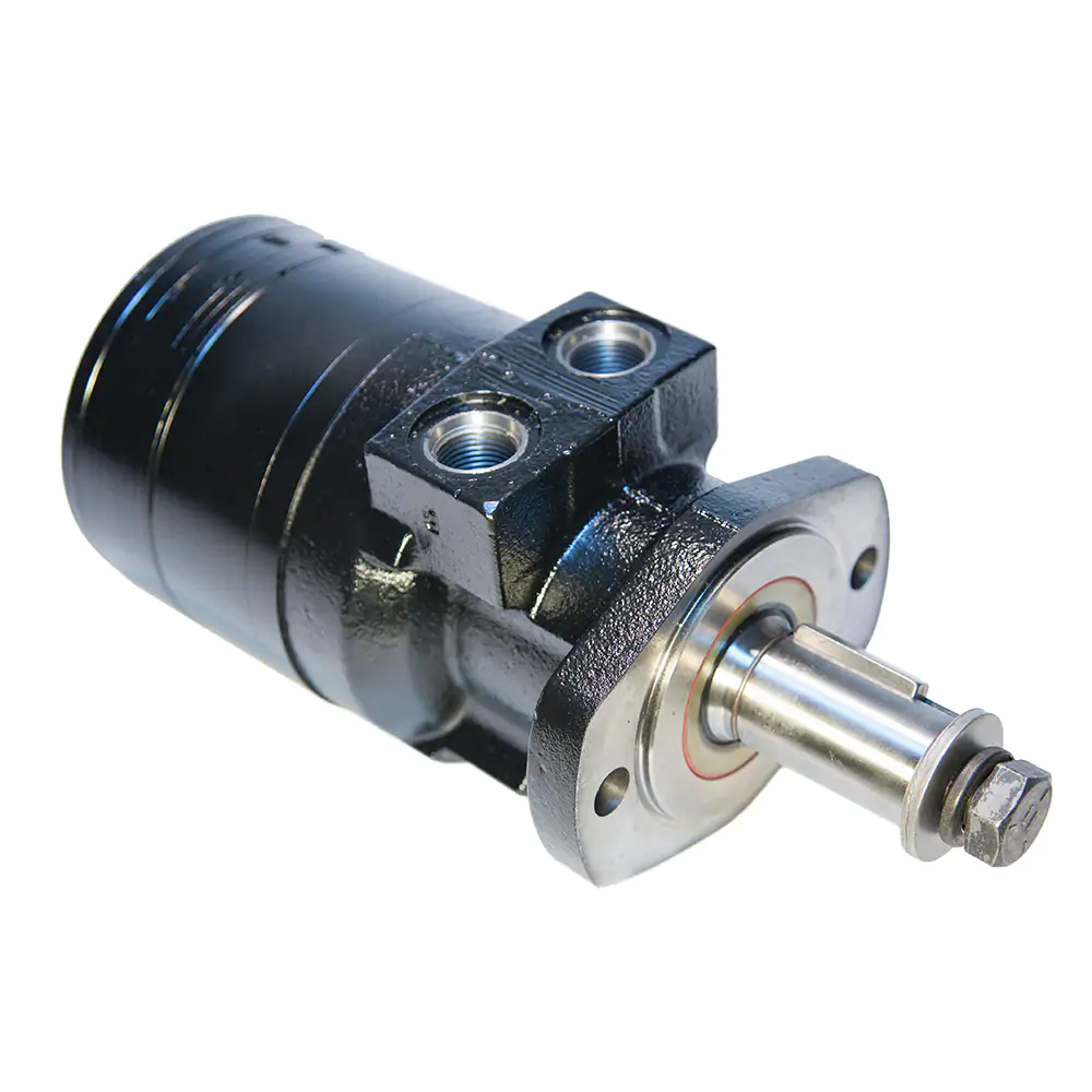
Maintaining optimal performance requires understanding the significance of component renewal and enhancement. Regularly updating essential elements not only extends the lifespan of the system but also improves efficiency and reliability.
| Component | Recommended Upgrade | Benefits |
|---|---|---|
| Seals | High-performance materials | Enhanced durability and leak resistance |
| Bearings | Precision-engineered types | Reduced friction and improved longevity |
| Housing | Reinforced designs | Increased strength and impact resistance |
| Valves | Advanced flow technology | Optimized fluid dynamics and performance |
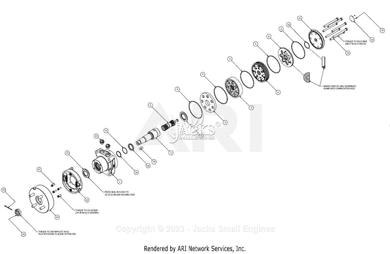
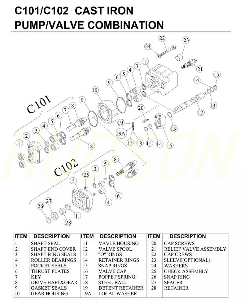
Reading the Parts Diagram
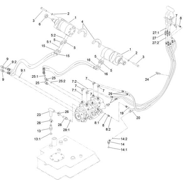
Understanding the visual representation of components is crucial for effective maintenance and repair. This section will guide you through the essential aspects of interpreting these illustrations, enabling you to identify and comprehend the various elements involved in a system.
Key Elements to Identify
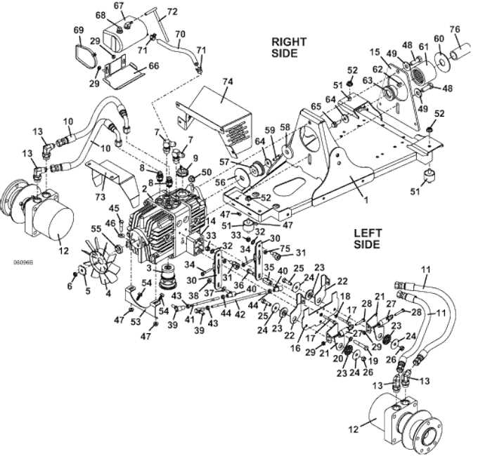
When examining the visual layout, it’s important to focus on the following components:
- Labels: Each component is often accompanied by annotations that describe its function.
- Connections: Arrows and lines indicate how parts interact with one another.
- Symbols: Unique icons may represent specific functions or types of elements.
Steps for Effective Interpretation
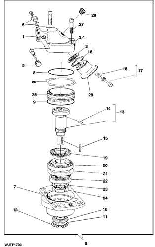
- Begin by familiarizing yourself with the overall layout.
- Identify each labeled component, noting its position and role.
- Trace the connections to understand how elements relate to one another.
- Refer to any accompanying documentation for detailed explanations of symbols.
By following these guidelines, you can enhance your understanding and ensure a smoother process when dealing with the intricate assembly of a system.
Tips for Efficient Troubleshooting
Effective problem-solving requires a systematic approach to identify and rectify issues efficiently. Utilizing the right techniques can streamline the process, reducing downtime and enhancing performance.
- Gather Information: Collect all relevant data regarding the malfunction. This includes operational history, error messages, and any recent changes made to the system.
- Visual Inspection: Conduct a thorough examination of the equipment. Look for signs of wear, leaks, or loose connections that may indicate underlying problems.
- Utilize Diagnostic Tools: Implement specialized tools and software designed for analysis. These can provide insights into performance metrics and help pinpoint issues more accurately.
Once you have gathered initial information, follow these steps to narrow down the cause:
- Isolate the Problem: Determine whether the issue is localized or widespread. Test individual components to see if they function correctly on their own.
- Check Documentation: Refer to manuals or guides relevant to the system. These resources often contain troubleshooting charts that can lead to quick solutions.
- Consult with Peers: Discuss the issue with colleagues or experts who may have encountered similar situations. Collaborative problem-solving can yield new perspectives.
Finally, maintain a record of the troubleshooting process. Documenting steps taken and solutions found can serve as a valuable reference for future issues, enhancing overall efficiency in the long run.