Understanding the essential elements of any mechanical system is crucial for maintaining its efficiency and ensuring long-term reliability. When working with advanced equipment, having a clear reference to the different elements that compose the machinery can be invaluable, especially during routine upkeep or repair tasks.
In this section, we will explore the major components involved in the proper functioning of a versatile cutting tool. By identifying and analyzing each part, you will be better equipped to handle any maintenance or troubleshooting that may arise, ensuring optimal performance in various conditions.
Detailed insights into the structural setup provide a solid foundation for anyone looking to extend the life of their equipment. Through this guide, we aim to make the identification and understanding of each part more accessible and intuitive, helping you tackle any technical challenges with confidence.
Overview of Key Components

The essential mechanisms within this equipment are designed to ensure efficient performance and reliability in various operations. By understanding the main elements, users can maintain and optimize functionality, ensuring longevity and effectiveness in demanding tasks.
Engine Assembly
The power source provides the necessary force to drive the tool’s functions. This includes critical parts like the cylinder and piston, which convert energy into mechanical movement. Regular maintenance of the engine is crucial for consistent operation.
Cutting System
The cutting mechanism, equipped with a durable blade, is the core of the tool’s operation. It is designed to handle tough materials with precision. Ensuring the sharpness and proper alignment of this component is key to achieving accurate results.
Handle and Grip Assembly Breakdown

The handle and grip section is crucial for providing the operator with control and comfort. This breakdown outlines the main elements involved in ensuring smooth functionality and ease of use.
- Main Handle: Designed for comfortable grip, the primary handle ensures stability during operation.
- Grip Surface: A textured material that enhances hand placement and minimizes slipping.
- Connection Points: These secure the handle to the main structure, providing balance and rigidity.
- Mounting Screws: Fasteners that ensure all components are tightly affixed to prevent movement or misalignment.
- Cushioning Elements: Added padding that absorbs vibrations, reducing hand fatigue and improving comfort over extended use.
Engine Mechanism Structure

The engine mechanism is a complex system designed to convert fuel energy into mechanical power, enabling the device to operate efficiently. Its internal structure involves various components working together harmoniously to ensure smooth operation. Understanding the arrangement of these elements is key to comprehending how the system functions overall.
| Component | Function | |
|---|---|---|
| Cylinder | Houses the piston and facilitates the combustion process that drives the engine. | |
| Piston | Moves within the cylinder to transfer energy from combustion to mechanical motion. | |
| Crankshaft | Transforms the piston’s linear motion into rotational energy to power the device. | |
| Connecting Rod | Links the piston to the crankshaft, transmitting the piston’s motion to the crankshaft. |
| Step | Description |
|---|---|
| 1 | Begin by examining the throttle linkage to ensure it is free of obstructions and functioning smoothly. |
| 2 | Adjust the throttle cable tension to provide adequate response without being overly tight or loose. |
| 3 | Check the trigger mechanism for any signs of wear or damage, replacing components if necessary. |
| 4 | Test the trigger action, ensuring it engages smoothly and returns to the idle position without hesitation. |
| 5 | Finalize the adjustments by confirming that the throttle opens fully when the trigger is fully engaged. |
By following these steps, users can ensure that the throttle control and trigger system operates efficiently, contributing to a better overall experience.
Clutch and Drive Mechanism
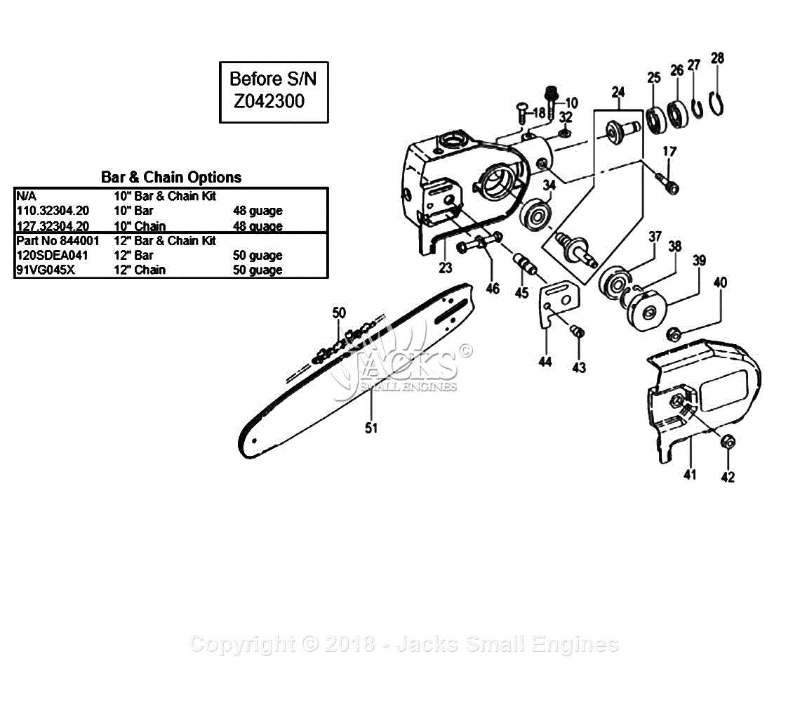
The clutch and drive mechanism is a vital component of a power tool, responsible for transmitting power from the engine to the working parts efficiently. This system enables the operator to control the tool’s operation and power delivery, ensuring optimal performance during use.
Functionality

This mechanism operates by engaging and disengaging the engine’s power based on user input. The key functions include:
- Transmitting torque from the engine to the cutting equipment.
- Allowing for smooth starts and stops during operation.
- Providing a safety feature to prevent damage from sudden changes in load.
Components
The main elements of the clutch and drive system include:
- Clutch Plates: Engage and disengage to control power transfer.
- Drive Shaft: Connects the engine to the cutting tool, transmitting power effectively.
- Springs: Maintain tension on the clutch plates for reliable engagement.
Protective Covers and Safety Parts
Ensuring safety while operating equipment is crucial for both the user and the machine. Protective covers and safety components play a significant role in minimizing risks and maintaining optimal functionality. These elements are designed to shield vulnerable areas from external damage and reduce the chances of accidental injuries during operation.
| Component | Description | Function |
|---|---|---|
| Safety Guard | A protective barrier that prevents contact with moving parts. | Reduces the risk of injuries by covering potentially dangerous areas. |
| Hand Protection Shield | A cover designed to protect the user’s hands from debris and sharp edges. | Enhances safety by providing a barrier against cuts and abrasions. |
| Engine Cover | A casing that protects the engine from dirt, debris, and physical damage. | Maintains engine performance by preventing contamination and damage. |
| Safety Latch | A mechanism that ensures components remain securely in place during operation. | Prevents accidental disassembly or movement of parts, enhancing safety. |
