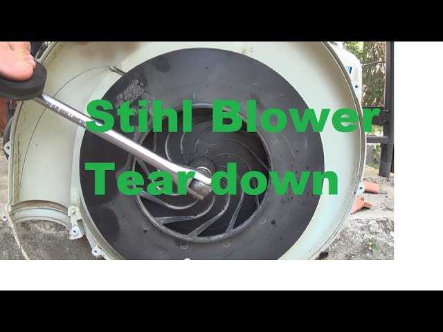
For those looking to maintain a high-performance leaf blower, understanding its internal configuration is key to keeping it running smoothly. Delving into the various components that make up this powerful device helps users identify potential issues and ensures timely maintenance, ultimately extending its lifespan.
Each element plays a crucial role in ensuring optimal operation, from the engine to the smaller, intricate mechanisms. Having a clear understanding of how these elements interact allows enthusiasts and professionals alike to optimize the device’s functionality, making it ideal for handling a wide range of outdoor tasks.
By exploring the internal structure and relationships between different components, users can gain deeper insights into maintaining and repairing their equipment. Such knowledge proves invaluable when addressing wear and tear or when a specific part needs replacement, ensuring that the machine continues to operate at
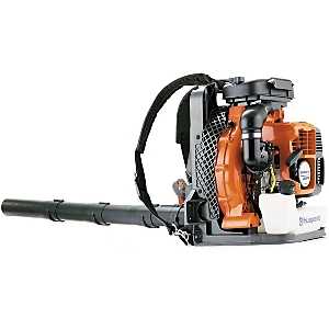
Overview of Stihl BR 600 Components
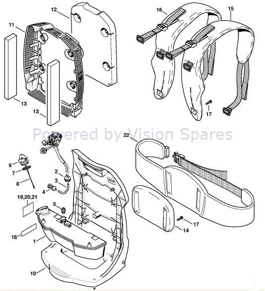
This section offers an insight into the essential elements that make up this high-performance leaf blower. By understanding the key mechanical and functional aspects, users can better appreciate the machinery’s efficiency and reliability. Each part plays a specific role in delivering a smooth operation and ensuring long-lasting service.
Main Assembly Structure
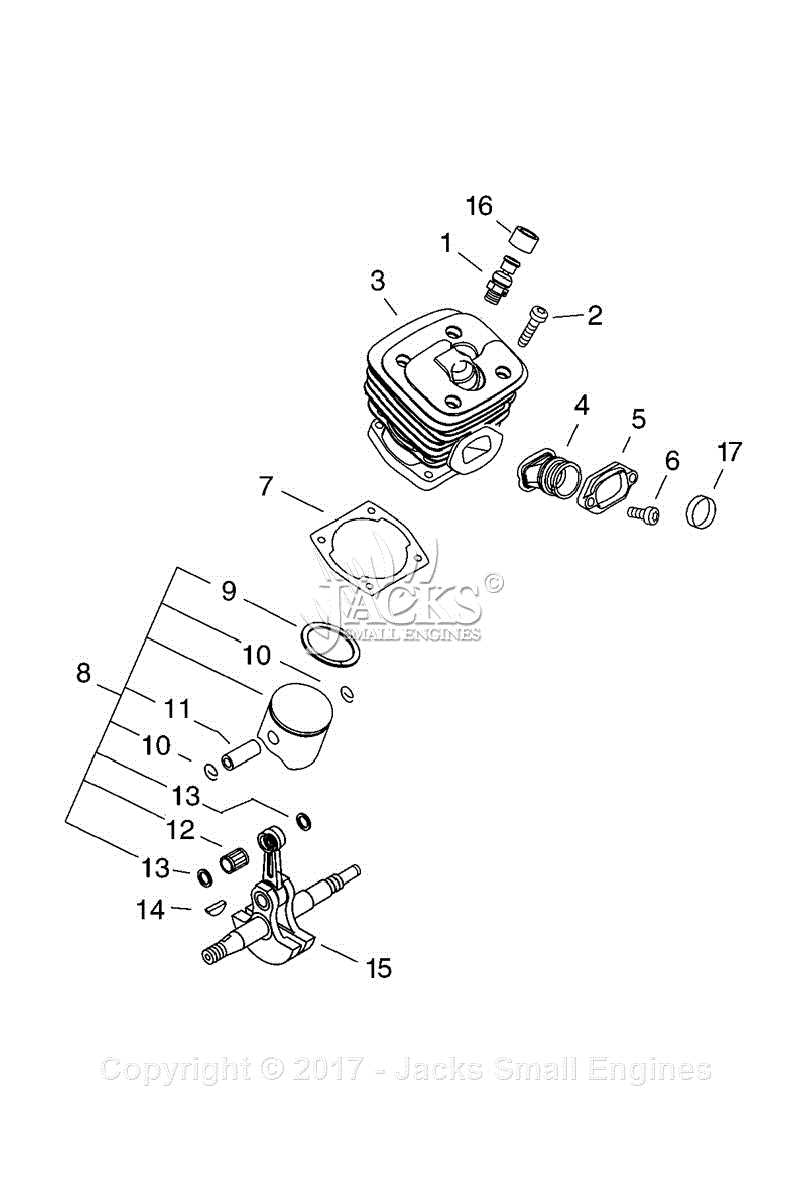
The blower features a robust frame that supports its core engine and other vital mechanisms. The structure includes a durable housing that protects internal components from external elements while maintaining optimal airflow. The engine block is strategically positioned to balance weight, offering ease of handling during prolonged use.
Key Functional Elements
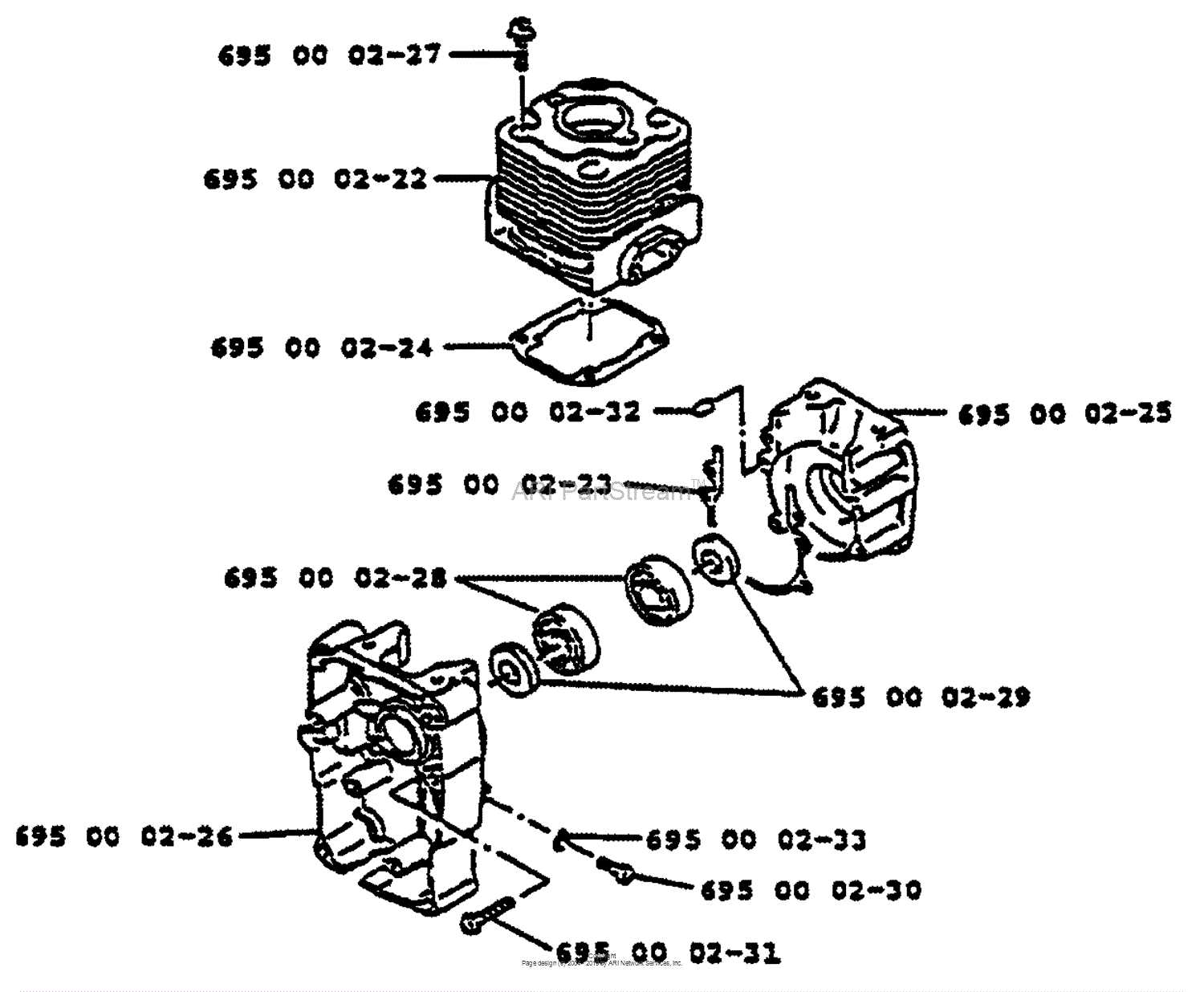
Various mechanisms contribute to the overall functionality, from the air intake system to the fuel supply setup. These elements work together seamlessly, ensuring consistent airflow and precise fuel distribution for effective performance. Below is a summary of some key sections and their purpose:
| Component |
Description |
Main Functionality of Key Parts
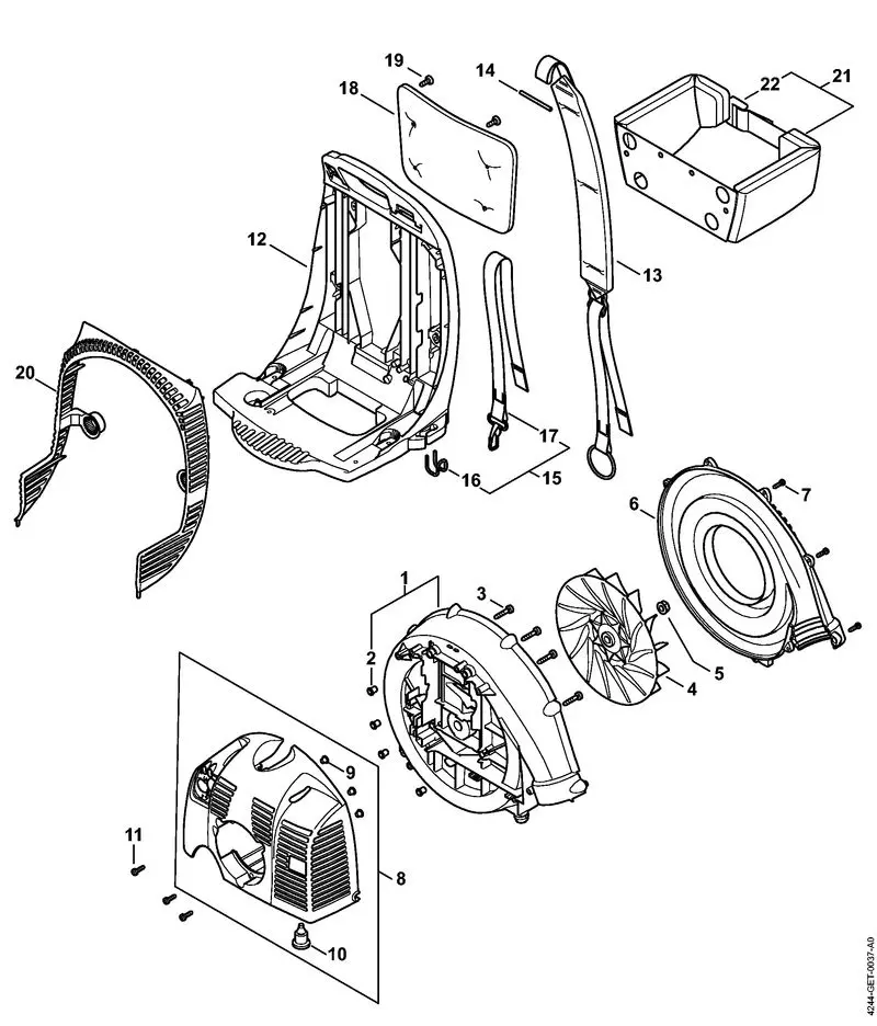
Understanding the primary roles of individual components can enhance maintenance efficiency and prolong the operational lifespan of the device. Each element plays a vital role, contributing to overall performance, and a deeper knowledge of their functions ensures better handling and timely upkeep.
Engine Component
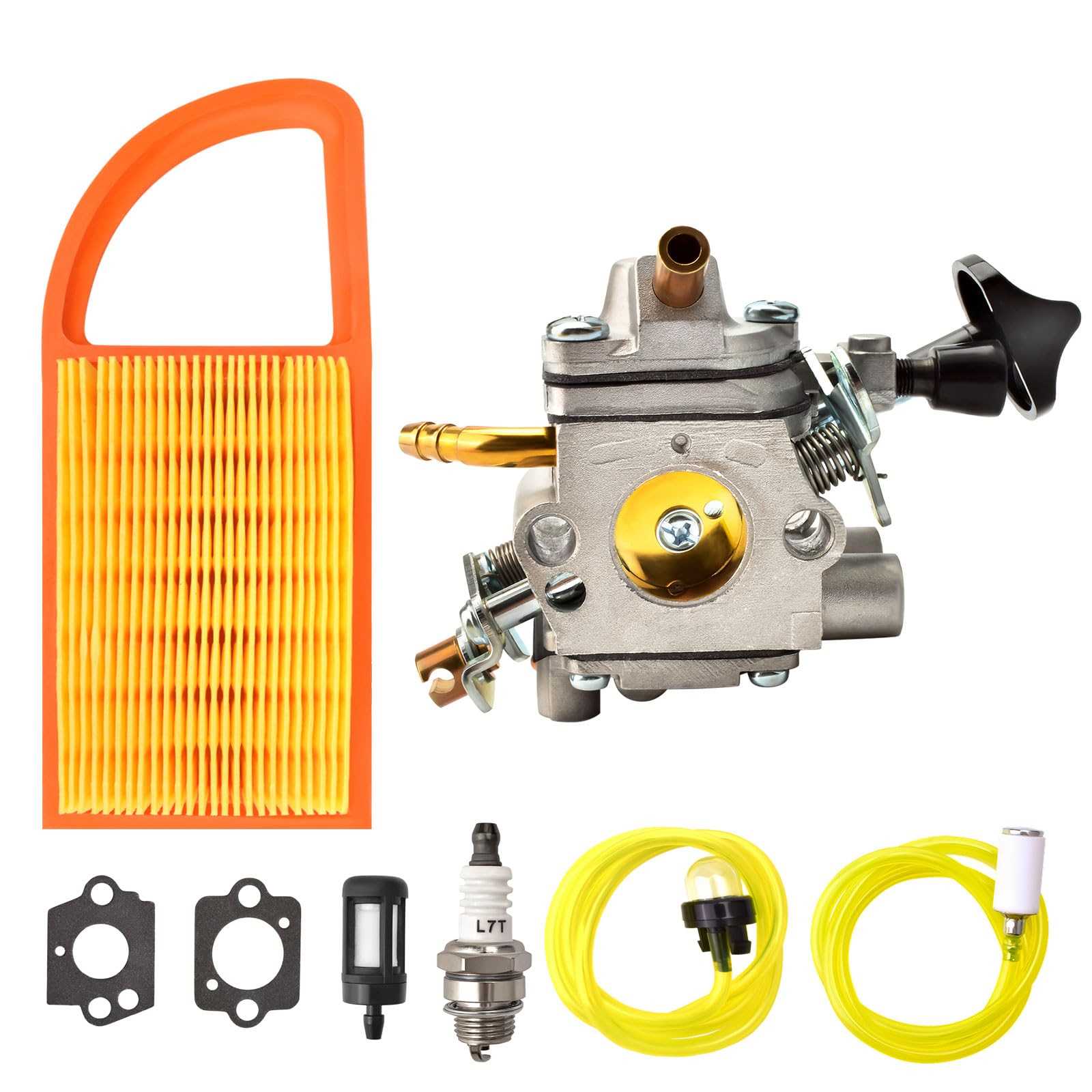
The core driving element transforms fuel into mechanical energy, powering the entire mechanism. Its precise design ensures optimal energy conversion, providing the necessary force for continuous operation. Proper maintenance of this part is essential for smooth and reliable performance, making it a key focus during servicing.
Air Circulation System
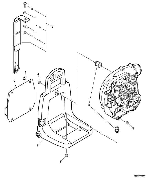
Airflow management is crucial for maintaining temperature stability and ensuring a clean environment for internal processes. This system ensures a consistent supply of air, facilitating efficient cooling and preventing overheating. Effective function of this system supports both fuel combustion and overall efficiency, making it an integral part of the equipment’s operation.
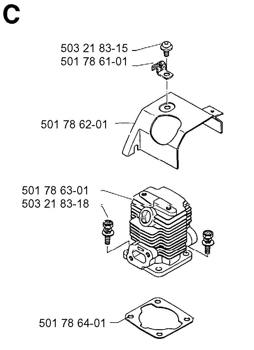
Understanding the Engine Assembly Structure
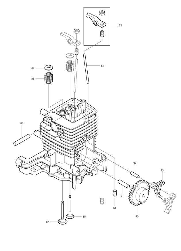
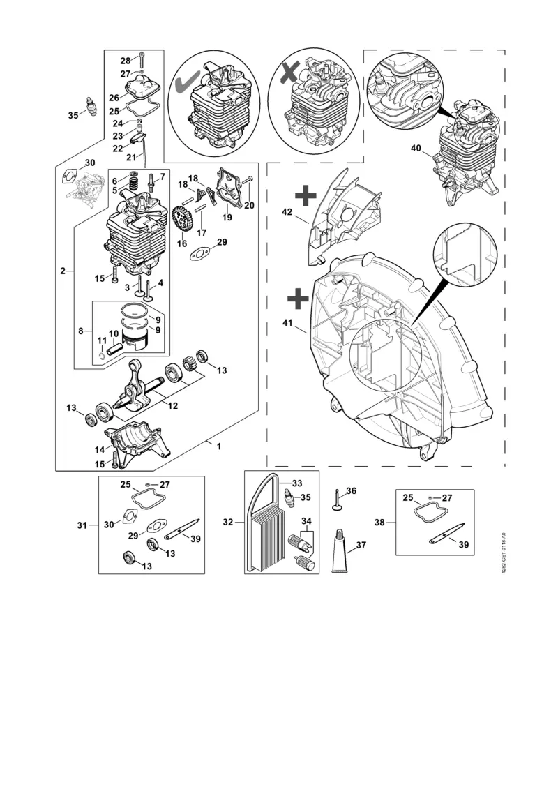
The engine assembly is a complex arrangement of interconnected elements that work in unison to provide power and functionality. Each component plays a crucial role in maintaining smooth operation, ensuring efficient combustion, and supporting various mechanical processes.
Exploring the key components of this system can help to understand how they interact, allowing for better maintenance and repair practices. Below are the main parts that make up this intricate mechanism:
- Cylinder and Piston: The cylinder houses the piston, which moves up and down to generate power through compression. This movement is fundamental for energy production within the engine.
- Crankshaft: Connected to the piston, the crankshaft converts the linear motion of the piston into rotational energy, which is then transferred to other parts of the system.
- Carburetor: Responsible for mixing fuel and air in precise proportions, the carburetor ensures proper combustion within the chamber. Its adjustments directly impact performance and efficiency.
- Cooling System: The cooling system helps dissipate heat generated during operation
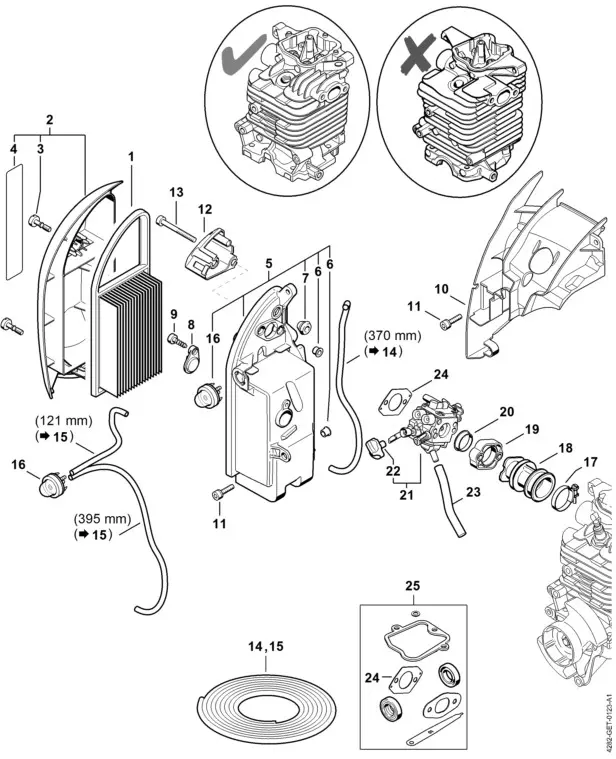
Air Filter System Explained
The air filter system is crucial for maintaining the efficiency and longevity of outdoor power equipment. Its primary role is to ensure that the engine receives clean airflow, free from debris and dust particles. By filtering out impurities, it helps prevent internal damage and ensures smooth operation.
Key Components of this system include a filtration element, a housing unit, and intake pathways. The filtration element traps unwanted particles, while the housing secures it in place, ensuring a proper seal. This design minimizes the risk of contaminants reaching the engine.
Maintenance and proper cleaning of the filtration element are essential to maintaining the performance of the system. A clogged filter can restrict airflow, leading to reduced engine power and potential overheating. Regular inspection and timely replacement of the element are recommended for optimal function.
Guide to the Ignition Module
The ignition system is a crucial component in any outdoor power equipment, ensuring a reliable start and smooth operation. This section delves into the key aspects of the module responsible for initiating the engine’s combustion process, its typical placement, and how it interacts with other elements of the machinery.
Understanding the functions and structure of this module helps diagnose issues such as irregular starting or power loss. Below is a detailed table illustrating the main components and their roles within the ignition system:
| Component |
Function |
| Coil Assembly |
Generates the necessary high voltage for the spark, ensuring proper combustion. |
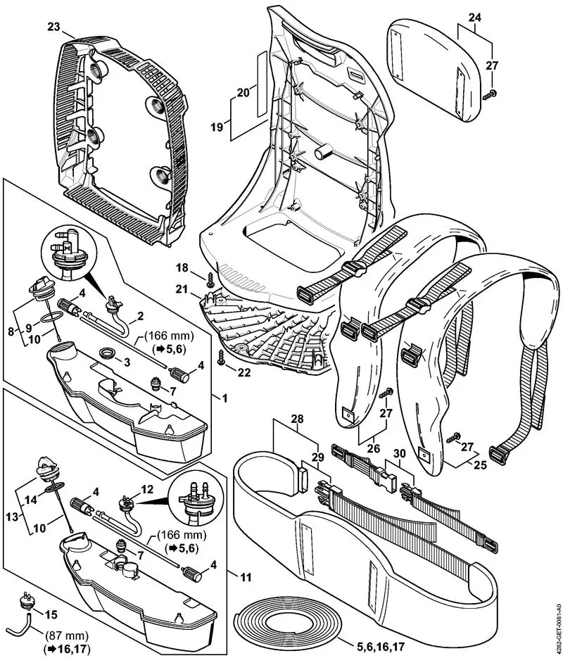
Fuel Tank and Line Configuration
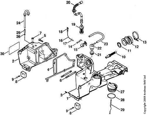
The fuel reservoir and associated conduits play a crucial role in the performance and efficiency of outdoor power equipment. Proper understanding of their arrangement can enhance operation and maintenance. This section outlines the configuration and function of these essential components, ensuring users can effectively manage fuel delivery and overall functionality.
Key Components
- Fuel Reservoir: The primary container for holding the liquid fuel, designed for optimal capacity and pressure management.
- Fuel Lines: Tubes that transport fuel from the reservoir to the engine, typically crafted from durable materials to withstand varying conditions.
- Fuel Filter: A device that removes impurities from the fuel before it reaches the engine, ensuring clean operation.
- Fuel Cap: Seals the reservoir, preventing leaks and contamination while allowing for pressure release when needed.
Configuration Details
- The fuel reservoir is mounted securely to avoid movement during operation.
- Lines are routed to minimize bends and kinks, allowing for smooth fuel flow.
- Filters are positioned strategically to ensure accessibility for maintenance and replacement.
- Caps are designed to be user-friendly, enabling quick refueling without spills.
Understanding the layout and function of these elements is vital for effective troubleshooting and maintenance. Regular checks and cleanings can prevent common issues, ensuring the longevity of the equipment.
Blower Tube and Nozzle Design
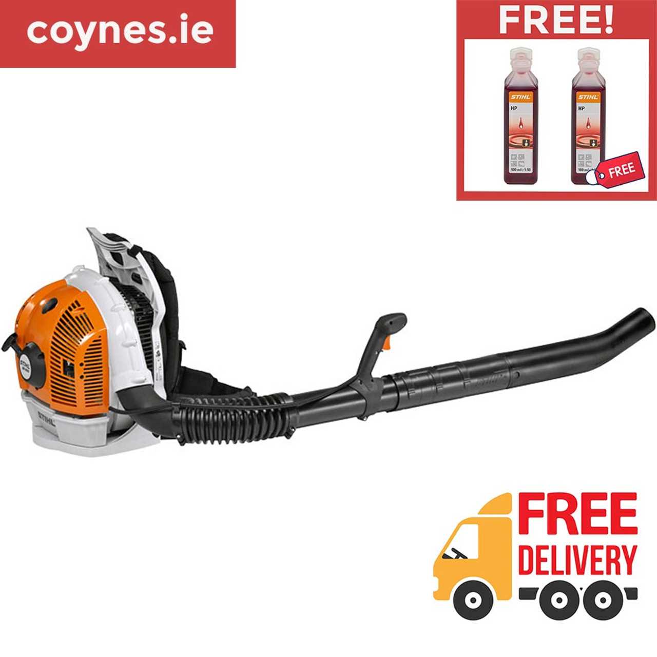
The design of the air delivery components plays a crucial role in the efficiency and performance of a blowing device. These elements are specifically crafted to optimize airflow, enhance control, and improve overall user experience. By examining the structure and functionality of the air conduit and attachment, one can appreciate how these features contribute to effective debris management.
Key Features of the Air Conduit
- Material Quality: High-grade materials ensure durability and resistance to wear, which is essential for prolonged usage.
- Ergonomic Design: The shape and angle of the tube are tailored to reduce strain on the operator while maximizing reach and maneuverability.
- Diameter Variations: Different sizes allow for versatility in handling various debris types, enabling users to switch between wide dispersal and focused airflow.
Attachment Options for Enhanced Functionality
- Standard Nozzle: Ideal for general cleanup tasks, providing a balanced airflow for effective debris removal.
- Funnel Nozzle: Concentrates the air stream for targeted applications, making it easier to clear stubborn or dense materials.
- Curved Nozzle: Designed for improved access in tight spaces, enhancing the user’s ability to navigate around obstacles.
Troubleshooting Common Component Issues
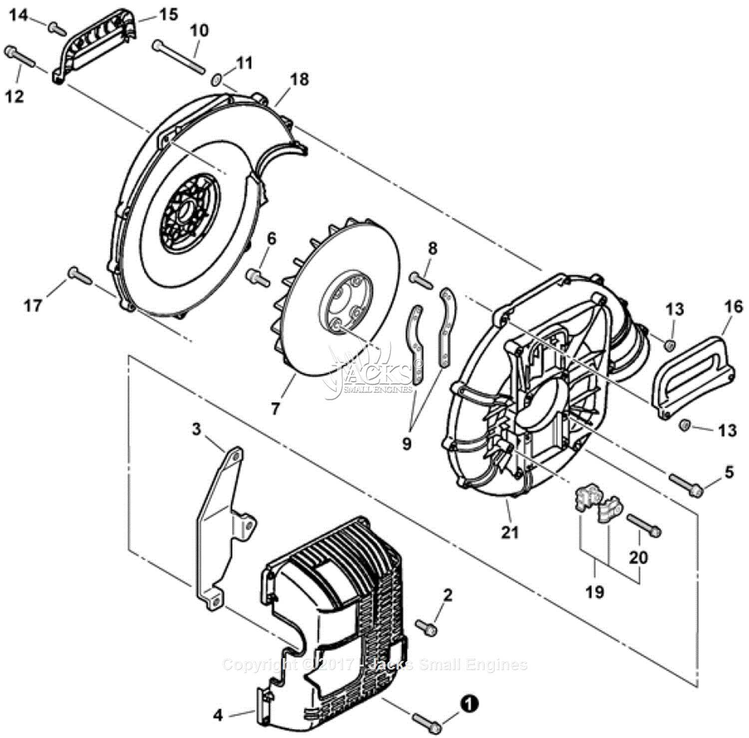
Identifying and resolving problems with key components can significantly enhance the performance of outdoor equipment. Understanding potential faults and their symptoms helps in maintaining optimal functionality, ensuring that devices operate smoothly and efficiently.
Common Symptoms and Solutions
| Symptom |
Possible Cause |
Recommended Action |
| Engine won’t start |
Insufficient fuel or clogged fuel filter |
Check fuel levels and replace the filter if necessary |
| Excessive vibration |
Worn or damaged components |
Inspect and replace worn parts |
| Poor performance |
Dirty air filter or spark plug |
Clean or replace the air filter and spark plug |
| Unusual noises |
Loose or damaged components |
Tighten or replace damaged parts |
Maintenance Tips
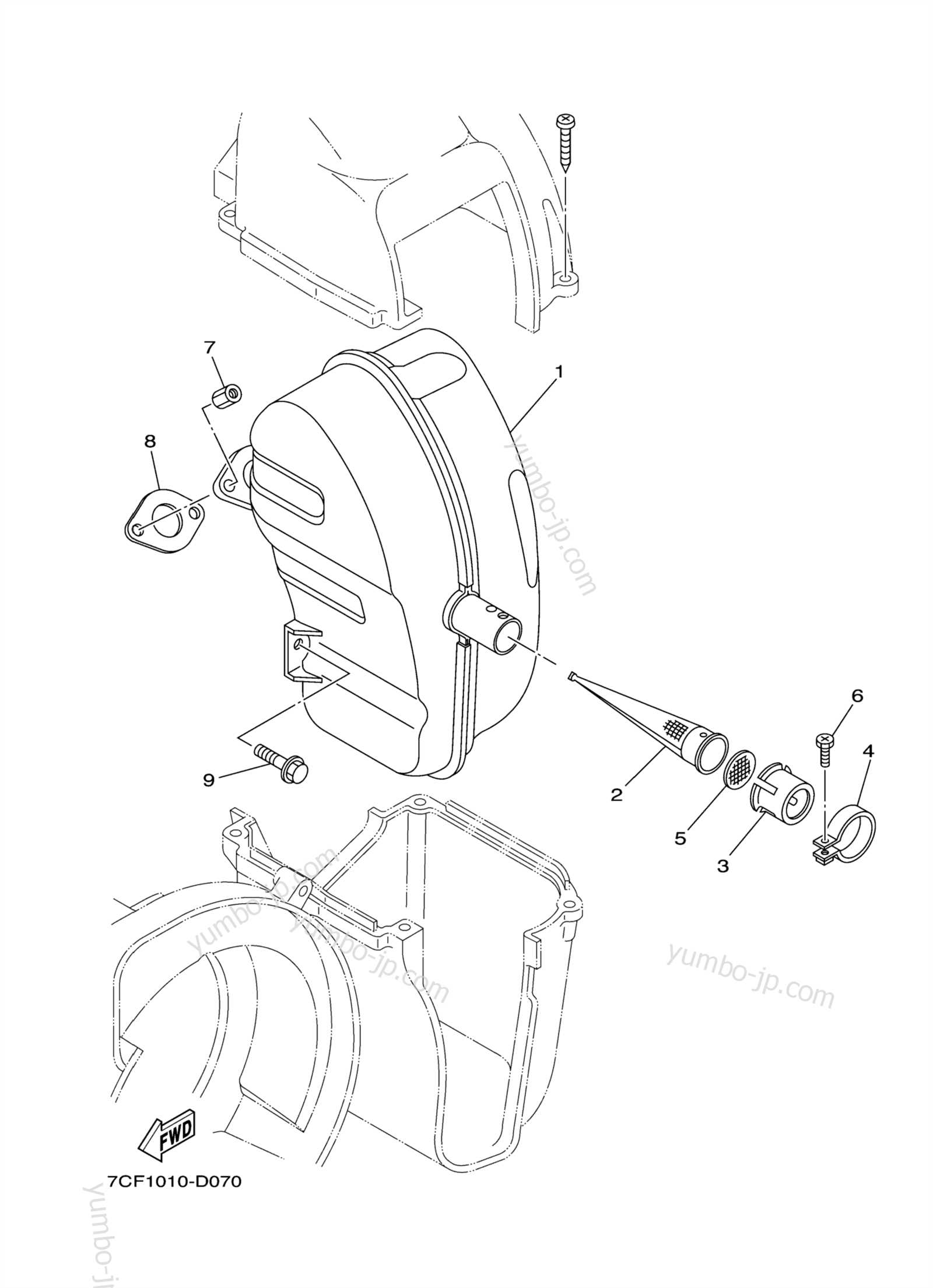
Regular maintenance is crucial for preventing issues. Ensure to clean filters, check fuel levels, and inspect components routinely to avoid future complications. Following the manufacturer’s guidelines will prolong the lifespan of the equipment and enhance its performance.
Maintenance Tips for Long-lasting Performance
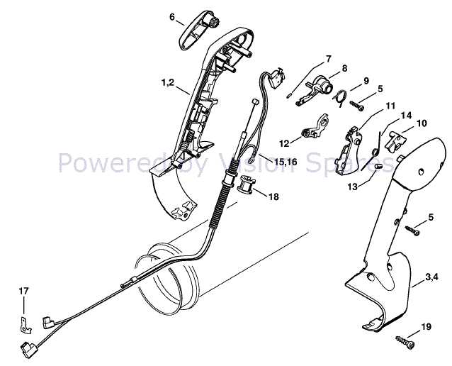
Ensuring the longevity of outdoor power equipment requires regular upkeep and attention to detail. Implementing a consistent maintenance routine can significantly enhance operational efficiency and prolong the lifespan of your machinery. Here are several essential practices to follow for optimal performance.
| Task |
Frequency |
Description |
| Air Filter Cleaning |
Every 10 hours of operation |
Remove the air filter and clean it with compressed air or a gentle brush to prevent clogging. |
| Fuel System Check |
Before each use |
Inspect the fuel lines and ensure there is fresh fuel to avoid starting issues. |
| Spark Plug Inspection |
Every 25 hours |
Check the spark plug for wear and replace it if necessary to maintain efficient ignition. |
| Blade Sharpening |
Every 20 hours |
Keep the cutting blades sharp for effective performance and to reduce strain on the engine. |
| General Cleaning |
After each use |
Remove debris and dirt from the equipment to prevent corrosion and ensure smooth operation. |
By adhering to these maintenance guidelines, users can enjoy reliable and efficient operation while maximizing the durability of their equipment.


