
Understanding the intricate structure of an outdoor machine can greatly improve its longevity and performance. Every mechanical system relies on the precise alignment and connection of its internal elements. Knowing how these elements fit together allows for smoother repairs and better maintenance, ensuring the tool runs efficiently and safely for extended periods.
By exploring the essential components and their placement, users can gain valuable insight into how each piece contributes to the tool’s overall operation. This knowledge not only aids in troubleshooting but also empowers users to replace or adjust specific elements with confidence, ensuring optimal functionality at all times.
In this guide, we’ll break down the key areas of this equipment, focusing on the main sections and their respective roles within the machine. Through this detailed examination, you’ll gain a deeper understanding of the mechanics behind this essential outdoor tool.
Ryobi 725r Components Overview
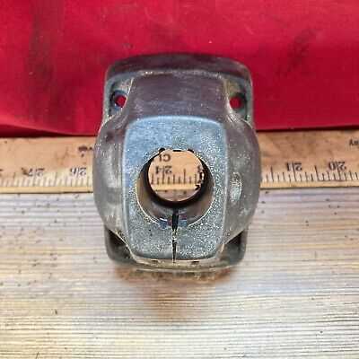
This section provides a comprehensive look at the various elements that make up the structure and functionality of this particular tool. Understanding the key components helps in maintaining, troubleshooting, and optimizing its performance.
| Component | Function |
|---|---|
| Engine Assembly | The power source driving the device, ensuring it operates efficiently in various conditions. |
| Fuel System | Regulates the mixture of fuel and air, ensuring smooth combustion and consistent power delivery. |
| Shaft Assembly | Connects the main power source to the working attachment, transmitting the required torque for operation. |
| Starter Mechanism | Initiates the engine’s operation, allowing for easy and efficient start-up. |
| Cutting Attachment | The working end of the device, designed for handling specific tasks depending on the application. |
Main Sections of the 725r Model
This tool is composed of several key components, each
Understanding the Engine Assembly Structure
The engine assembly plays a crucial role in ensuring the overall functionality of the equipment. By understanding the structure and interaction of its various components, you can achieve optimal performance and prolong the lifespan of the machine. In this section, we will explore the key elements of the engine system and how they work together to deliver reliable operation.
Main Components of the Engine Assembly
- Cylinder: The core of the engine, where the fuel combustion occurs, powering the device.
- Piston: This moving part inside the cylinder transmits the energy created by combustion to the crankshaft.
- Crankshaft: Converts the linear motion of the piston into rotational energy, driving the output shaft.
- Carburetor: Regulates the mixture of air and fuel, ensuring proper combustion in the cylinder.
- Main Grip: The primary section where the user holds the device. It offers stability and control during use, designed to reduce fatigue.
- Control Levers: These allow the user to engage and disengage various operational modes. They are ergonomically positioned to ensure quick and responsive adjustments.
- Throttle Mechanism: A crucial element for adjusting the speed of the engine. It is typically found near the handle for easy access and control.
- Safety Switch: Designed to prevent accidental startups, this feature adds an extra layer of protection by requiring intentional activation before use.
- Blade assembly: Ensures smooth and effective cutting, designed to handle various types of vegetation with ease.
- Spool housing: Protects and secures the cutting line, allowing for easy replacement and optimal line release.
- Line guide: Directs the cutting line for precision trimming, minimizing wear and improving efficiency.
- Bearing system: Provides smooth rotation and reduces friction, extending the lifespan of the head assembly.
Handle and Control System Breakdown
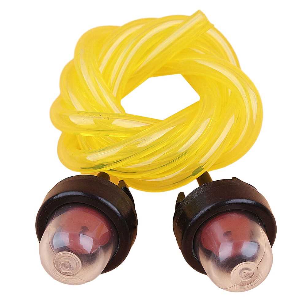
The operational efficiency of the machine heavily relies on a well-designed control setup. The handle and control system are central to guiding the device and ensuring safe and comfortable operation. This section provides a breakdown of the key components that make up this critical system, allowing for a better understanding of their functions and interdependencies.
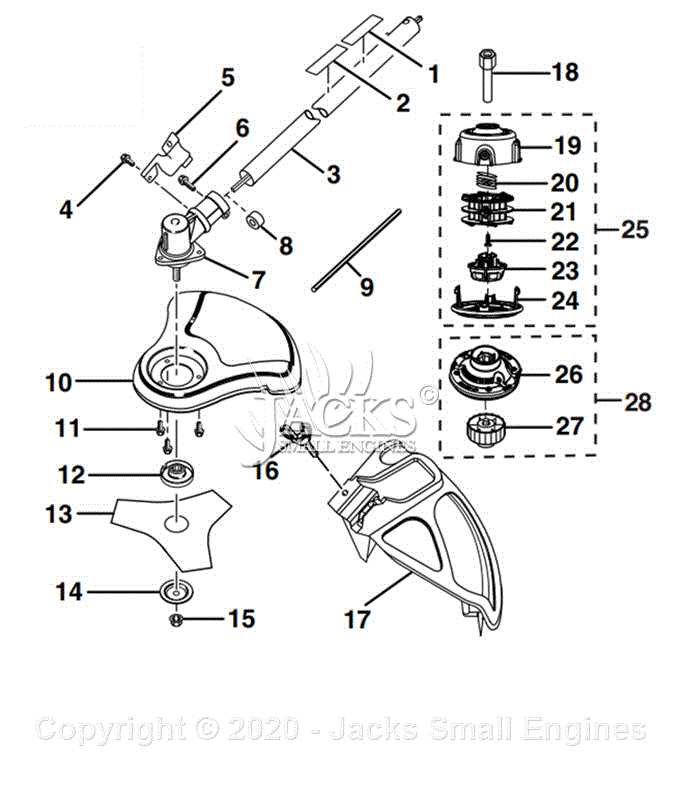
Detailed View of the Cutting Head
The cutting head is one of the most crucial components, responsible for ensuring efficient trimming and precise operation. In this section, we will explore the individual elements that make up this part, detailing their function and importance in the overall operation. Understanding the structure and assembly of this segment is essential for both maintenance and repair.
Core Components
Maintenance Tips
- Regularly check the blade for sharpness and signs of damage.
Fuel Tank and Line Layout
This section provides a comprehensive overview of the fuel reservoir and its associated piping system, essential for optimal operation of outdoor power equipment. Understanding the arrangement and connectivity of these components is vital for effective maintenance and troubleshooting.
The fuel tank serves as the primary storage unit, delivering the necessary fuel to the engine through a series of lines and connectors. Proper configuration of these elements ensures a steady flow and prevents potential issues.
- Fuel Tank: The main container that holds the fuel, typically made of durable plastic or metal.
- Fuel Lines: Flexible tubes that transport fuel from the tank to the engine. These lines must be intact to prevent leaks.
- Filter: Located along the fuel line, this component ensures that impurities do not enter the engine.
- Fuel Cap: Seals the tank and prevents contamination while allowing for ventilation.
- Priming Bulb: A rubber bulb used to draw fuel into the lines before starting the engine.
Each component plays a critical role in the functionality of the equipment. Regular inspection of the tank and fuel lines helps in identifying wear and tear, ensuring reliable performance.
Ignition System Parts and Function
The ignition system is a crucial component in the operation of small engines, playing a vital role in initiating the combustion process. It ensures that the fuel-air mixture ignites at the optimal moment, allowing the engine to run smoothly and efficiently. Understanding the elements that comprise this system is essential for effective troubleshooting and maintenance.
Key Components
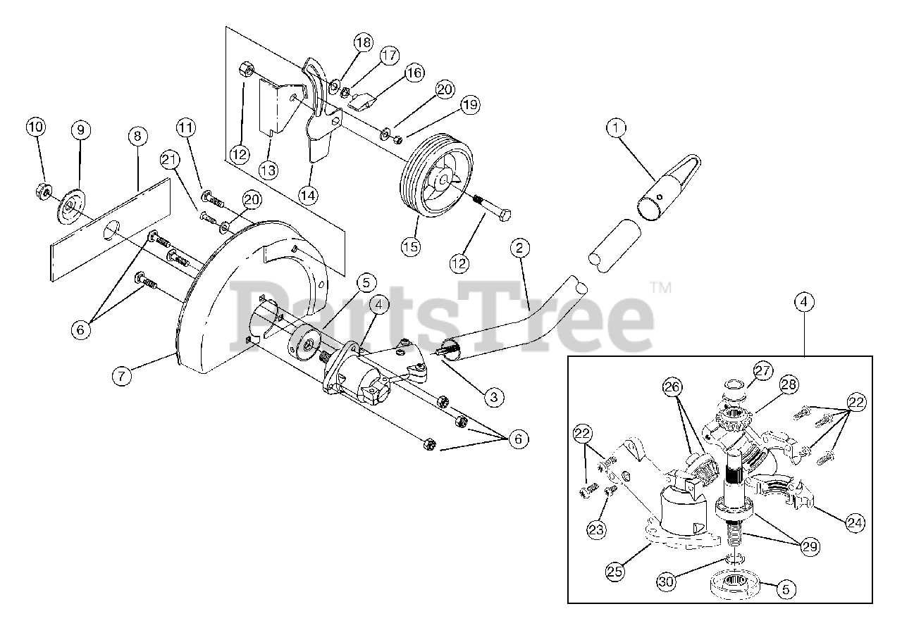
Central to the ignition system are several key elements. The spark plug generates the necessary spark that ignites the fuel mixture within the combustion chamber. The ignition coil transforms low battery voltage into a high-voltage pulse, which is sent to the spark plug. Additionally, the flywheel plays a significant role by housing magnets that help generate the electrical energy needed for the ignition coil.
Functionality Overview
When the engine is cranked, the flywheel rotates, producing a magnetic field that activates the ignition coil. This generates a high-voltage current, which travels through the ignition wires to the spark plug. Once the voltage reaches the spark plug, it creates a spark that ignites the fuel-air mixture, powering the engine. This cycle repeats, allowing the engine to operate continuously. Proper functionality of each component is essential for optimal performance and reliability.
Throttle and Cable Assembly Guide
This section provides essential insights into the assembly and functionality of the throttle mechanism and cable system. Understanding the components and their interactions is crucial for maintaining optimal performance in various equipment applications.
Components Overview
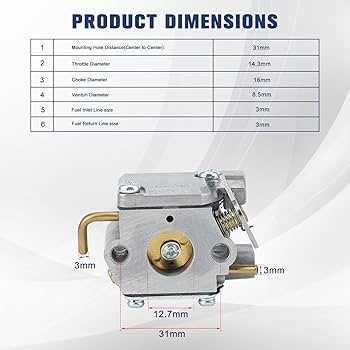
The throttle assembly typically consists of several key elements that work together to control the engine speed and power output. Each part plays a vital role in ensuring smooth operation and responsiveness.
| Component | Description |
|---|---|
| Throttle Lever | Acts as the control point for the user to adjust the speed of the engine. |
| Cable | Transmits the movement from the throttle lever to the engine’s throttle plate. |
| Carburetor Linkage | Connects the cable to the carburetor, allowing for fuel-air mixture adjustments. |
| Return Spring | Ensures the throttle returns to the idle position when the lever is released. |
Assembly Instructions

Proper installation of the throttle and cable assembly is vital for functionality. Begin by securing the throttle lever in its designated position. Next, attach the cable, ensuring it runs smoothly without any twists or kinks. Finally, connect the linkage to the carburetor, and confirm that the return spring is properly fitted to guarantee the lever returns to its neutral state.
Common Replacement Parts and Maintenance Tips
Regular upkeep of your equipment is essential for ensuring optimal performance and longevity. Understanding which components are prone to wear and how to care for them can significantly enhance the efficiency of your device. This section provides insights into frequently replaced components and essential maintenance practices.
Fuel Filters: These are crucial for keeping your engine running smoothly. Replacing the fuel filter regularly helps prevent clogs that can lead to performance issues. Check and replace as needed based on usage and environmental conditions.
Air Filters: Clean air filters are vital for optimal engine performance. A dirty filter can restrict airflow, causing the engine to work harder. Regularly inspect and clean or replace the air filter to maintain efficiency.
Cutting Blades: Dull or damaged blades can hinder cutting performance. Sharpen or replace blades as necessary to ensure clean cuts and to reduce the strain on the engine.
Spark Plugs: These components play a critical role in ignition. Worn or fouled spark plugs can cause starting issues and poor performance. Regularly inspect and replace spark plugs to maintain reliable operation.
Maintenance Tips: Regularly cleaning your equipment after each use is essential. Remove debris and dirt that may accumulate, as this can lead to wear over time. Additionally, lubricate moving parts according to the manufacturer’s recommendations to prevent friction and prolong the lifespan of your device.