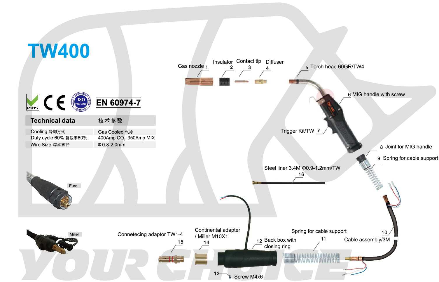
In the realm of metalworking, a comprehensive grasp of the machinery involved is essential for efficiency and precision. This section aims to illuminate the intricate elements that contribute to the functionality of welding tools. By exploring these components, we can enhance our understanding and application of these vital devices.
Familiarity with the various mechanisms not only boosts productivity but also ensures safety during operations. Each piece plays a crucial role, influencing performance and outcome. A deeper insight into these mechanisms allows for improved techniques and better results in metal joining tasks.
Moreover, recognizing how each element interacts within the system can lead to more informed decisions regarding maintenance and upgrades. As we delve into this topic, we will uncover the ultimate significance of each component, ultimately enhancing our overall approach to welding.
Understanding Welder Parts Diagrams
Grasping the intricacies of equipment layouts is essential for anyone working in the field. These visual representations provide a comprehensive overview of components and their interrelationships, facilitating a deeper insight into functionality and maintenance.
The Importance of Clear Representations
Clear visuals play a crucial role in troubleshooting and repairs. They guide users in identifying specific elements, ensuring efficient service and reducing downtime.
Common Components in Equipment Layouts
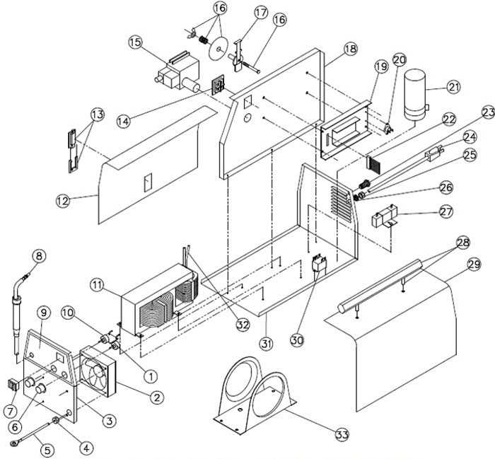
| Component | Description |
|---|---|
| Power Source | The main unit providing energy for operation. |
| Electrode Holder | Holds the electrode in place during use. |
| Ground Clamp | Establishes a connection to prevent electrical hazards. |
| Cooling System | Prevents overheating of components during prolonged use. |
Importance of Accurate Diagrams
Precise illustrations play a crucial role in various technical fields. They serve as essential references that guide professionals in understanding complex mechanisms and components.
- Facilitates effective communication among team members.
- Enhances the ability to troubleshoot issues efficiently.
- Ensures consistency in manufacturing and assembly processes.
- Reduces the risk of errors during repairs or maintenance.
By utilizing well-crafted visuals, technicians can delve deeper into their tasks, leading to better outcomes and ultimate satisfaction in their work.
Main Components of Welding Equipment
The functionality of welding machinery relies on a variety of essential elements that work together seamlessly. Understanding these fundamental components is crucial for anyone looking to master the art of joining materials through heat and pressure.
Key Elements
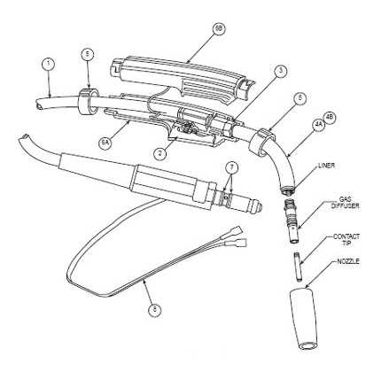
- Power Source
- Electrode Holder
- Ground Clamp
- Welding Torch
- Filler Material
Supportive Accessories
- Protective Gear
- Welding Helmet
- Gloves
- Apron
Each of these elements contributes to the ultimate effectiveness and safety of the welding process, allowing operators to achieve high-quality results.
Common Symbols Used in Diagrams
Understanding the visual language of technical illustrations is crucial for anyone working in engineering or maintenance. These representations utilize specific icons and markings to convey complex information efficiently. Recognizing these symbols can greatly enhance comprehension and communication within technical documentation.
One frequently encountered symbol is the circle, often used to denote components or connections. Arrows are essential as they indicate the direction of flow or movement, guiding the viewer through the assembly process. Rectangles typically represent physical elements, while dashed lines may signify optional or hidden features. Each symbol serves a distinct purpose, contributing to a cohesive understanding of the overall structure.
Color coding also plays a vital role in these visual aids, providing additional layers of meaning. For example, red often indicates caution or danger, while green suggests safety or operational status. By mastering these common representations, individuals can navigate technical illustrations with greater ease and confidence.
How to Read a Welder Diagram
Understanding technical illustrations is crucial for effective maintenance and operation of welding equipment. These visual representations provide valuable information about components, connections, and functionalities. Learning to interpret these images can enhance your troubleshooting skills and overall proficiency.
Key Elements to Identify
- Symbols: Familiarize yourself with common icons used to represent various components. Each symbol has a specific meaning that can clarify the role of each part.
- Lines: Different types of lines indicate various connections, such as power sources or signal paths. Recognizing these can help you trace electrical flow.
- Labels: Read all annotations carefully. Labels often provide essential information about specifications and operational parameters.
Step-by-Step Approach
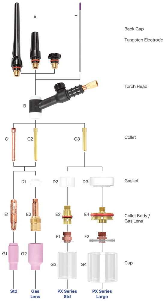
- Start by examining the overall layout to grasp the equipment’s structure.
- Identify the main components, using symbols and labels to understand their functions.
- Trace the connections, following the lines to see how parts interact.
- Refer to the accompanying legend or key for clarification on any unfamiliar symbols.
By following these steps and paying close attention to details, you can effectively interpret technical illustrations, leading to improved performance and safety in your work.
Maintenance Tips for Welding Parts
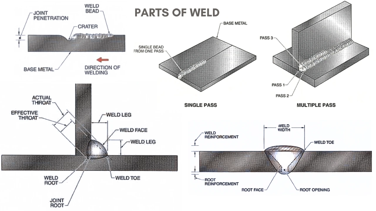
Ensuring the longevity and performance of your equipment requires consistent care and attention. By following a few straightforward practices, you can enhance the efficiency and safety of your tools, reducing the likelihood of unexpected failures. Here are some essential maintenance tips to keep your equipment in top condition.
Regular Cleaning
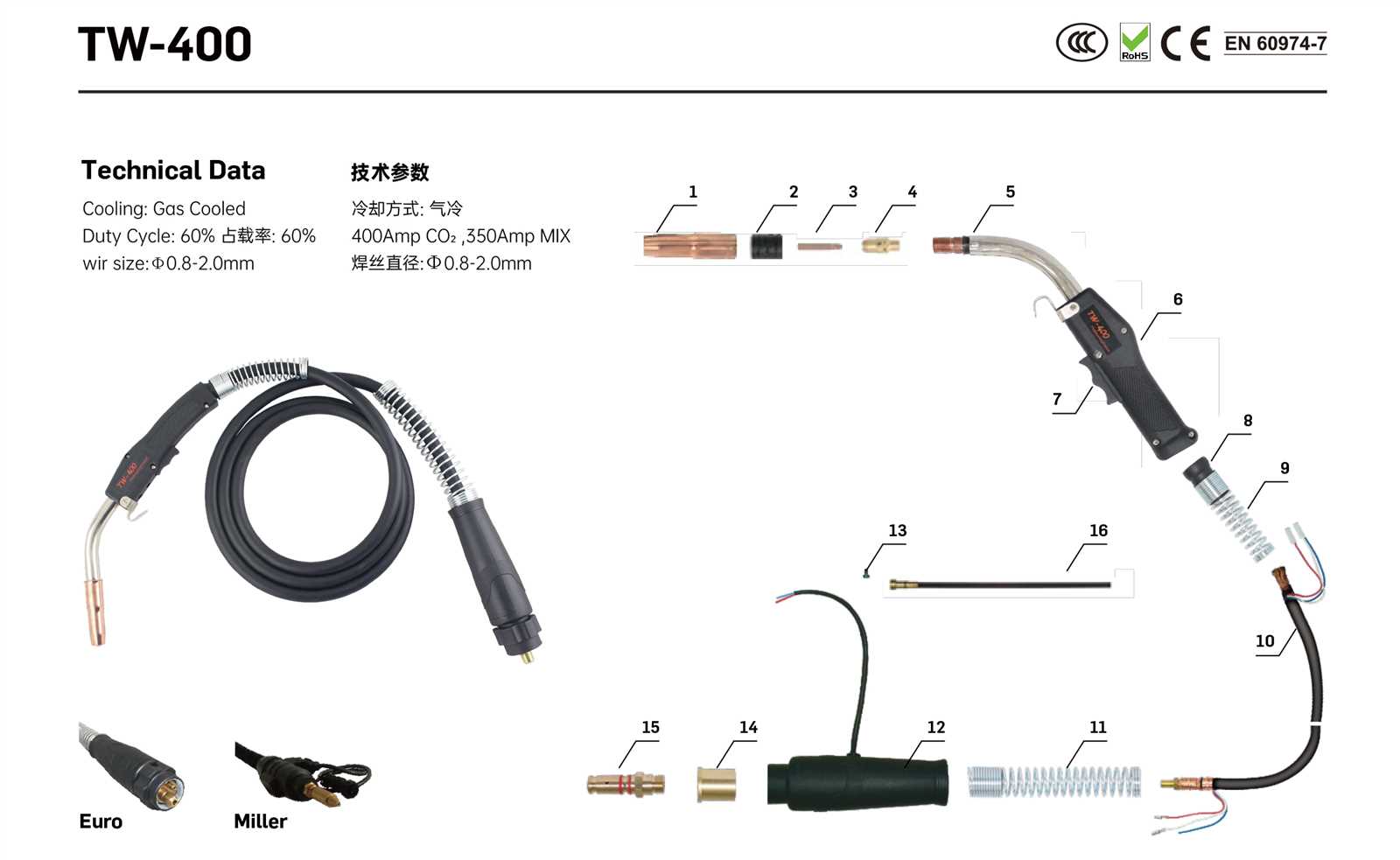
Keeping your equipment clean is vital for optimal performance. Dust, debris, and residue can negatively impact functionality. Consider these cleaning practices:
- Use a soft brush to remove dust and particles from surfaces.
- Wipe down components with a damp cloth to eliminate residue.
- Inspect and clean any air filters regularly to ensure proper airflow.
Routine Inspections
Regular checks can help identify wear and tear before it leads to significant issues. Implement the following inspection routine:
- Examine all cables for fraying or damage.
- Check connections and fittings for tightness.
- Inspect for signs of corrosion on metal surfaces.
By adhering to these maintenance practices, you can prolong the life of your equipment and maintain high-quality performance over time.
Identifying Faulty Components Easily
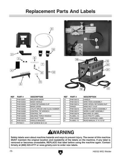
Understanding how to spot defective elements in machinery can significantly enhance maintenance efficiency. By recognizing signs of wear or malfunction early, operators can prevent costly downtime and ensure optimal performance.
Start by familiarizing yourself with the functionality of each element within the system. Regular inspections should focus on visual indicators, such as discoloration or unusual wear patterns. Additionally, monitoring performance metrics can reveal inconsistencies that signal underlying issues.
Utilizing diagnostic tools can also aid in pinpointing problematic components. Tools like multimeters and thermal cameras allow for detailed analysis, making it easier to identify faults that may not be visible to the naked eye. This proactive approach leads to more effective repairs and prolongs the lifespan of the equipment.
Lastly, keeping comprehensive records of maintenance activities can provide valuable insights over time. By analyzing trends and recurring issues, operators can anticipate failures and implement preventive measures before they escalate.
Resources for Detailed Diagram References
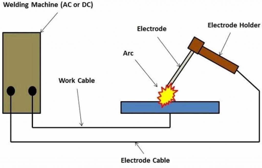
Accessing comprehensive visual guides is essential for anyone looking to enhance their understanding of equipment components. Such resources provide clarity and facilitate better maintenance and repair practices. Below are various avenues to explore for high-quality references.
- Manufacturer Websites: Many manufacturers offer extensive resources on their official sites, including manuals and schematics.
- Technical Forums: Online communities dedicated to specific trades often share valuable insights and diagrams among members.
- Online Retailers: Websites that specialize in selling equipment frequently provide detailed visuals in product descriptions.
- Educational Platforms: Websites focused on vocational training may offer courses that include detailed guides and illustrations.
For more specific needs, consider the following:
- YouTube Tutorials: Many experts create visual content that breaks down complex systems into understandable segments.
- Technical Books: Comprehensive manuals available in libraries or bookstores often include intricate illustrations and explanations.
- Trade Magazines: Subscribing to industry-specific publications can provide insights and visual references tailored to current practices.
Utilizing these resources can significantly improve one’s knowledge and skills in understanding and working with various machinery components.
Advancements in Welding Technology Today
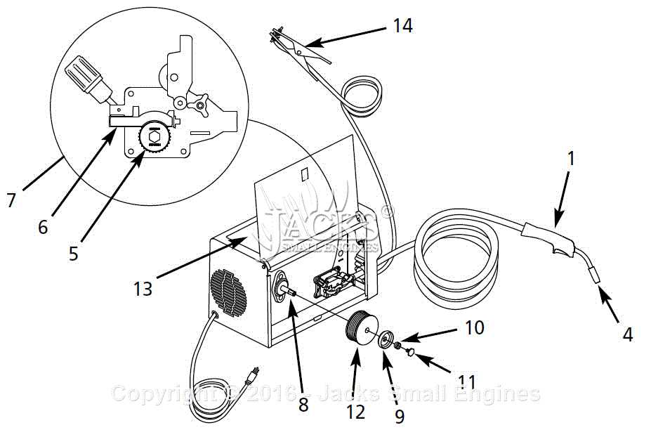
In recent years, the field of joining materials has experienced remarkable innovations that significantly enhance efficiency, precision, and safety. These advancements are reshaping industries, from manufacturing to construction, leading to improved productivity and reduced operational costs.
Automation and robotics have played a crucial role in this evolution. The integration of automated systems allows for consistent quality and higher speed, reducing the risk of human error. Robots equipped with advanced sensors and artificial intelligence are now capable of adapting to various conditions, ensuring optimal results in diverse environments.
Furthermore, new materials and techniques are continuously being developed. Innovations such as laser and electron beam techniques enable high precision and minimal thermal distortion, making them ideal for delicate projects. The exploration of advanced alloys and composites also contributes to stronger and lighter structures, which is essential in modern engineering.
Another significant improvement is in the realm of safety and monitoring. Enhanced protective gear and real-time monitoring systems are now standard, reducing health risks for operators. Technologies such as wearables and smart sensors facilitate a safer working environment by tracking exposure to harmful elements.
In conclusion, the ongoing advancements in the field of joining materials not only streamline processes but also set new standards for quality and safety. As these technologies continue to evolve, they promise to open new horizons in various sectors, driving innovation and economic growth.