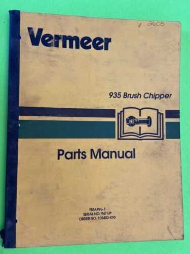
Vermeer BC1000XL Parts Diagram Overview

In diagram

vermeer bc1000xl parts diagram

This section delves into the intricate assembly of a high-performance machine, essential for those who seek to maintain or repair their equipment effectively. With numerous interconnected elements, each part plays a crucial role in the overall functionality. A clear understanding of the arrangement can greatly enhance maintenance efficiency, ensuring longevity and optimal operation.

Exploring the internal framework of this machinery reveals a complex network where each component must be understood in detail. Identifying the right elements within this setup can be the key to troubleshooting or enhancing performance. Such knowledge allows for a smoother workflow when handling maintenance tasks, making it easier to pinpoint and address issues.

The comprehensive breakdown provided here will guide you through each essential segment of the equipment’s structure. From the internal mechanisms to the exterior framework, the focus is on helping users comprehend how these elements interact to achieve the desired output. This insight is invaluable for anyone looking to optimize the machine’s use or undertake repair tasks with confidence.

Overview of Key Components in Vermeer BC1000XL
vermeer bc1000xl parts diagram

This section highlights the critical elements that ensure smooth operation and reliability of the equipment. Each component plays a vital role, contributing to the overall efficiency and functionality of the machine, helping to handle various tasks effectively.

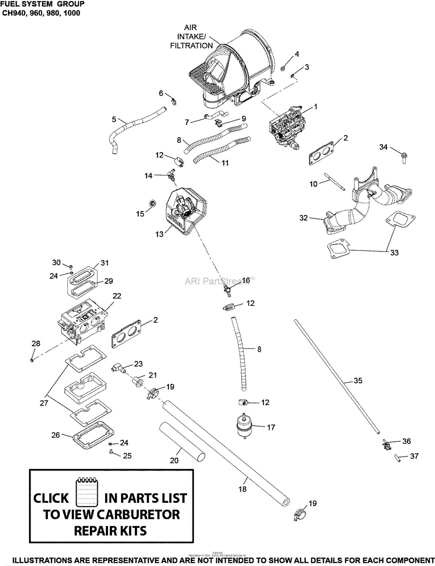
Engine Assembly and Drive System
vermeer bc1000xl parts diagram

The power unit drives the entire system, providing the necessary force for processing. This segment includes a robust motor that offers consistent energy output, paired with a transmission that ensures seamless power delivery. Together, they maintain the machine’s performance under different working conditions, allowing for effective handling of challenging materials.

Cutting Mechanism and Feed System
vermeer bc1000xl parts diagram

The processing unit is at the core of the material handling capability. It includes a precision cutting assembly and an advanced feed mechanism, designed to manage materials of various sizes. This arrangement ensures smooth flow and effective reduction of materials, optimizing productivity.

Component Description
Power Source Common Maintenance Parts for BC1000XL

vermeer bc1000xl parts diagram

Regular upkeep of this machine is essential to ensure its longevity and optimal performance. Certain components are more likely to require attention due to their frequent use and exposure to wear and tear. By addressing these key elements, users can maintain efficiency and avoid potential downtime.

Filters and Fluids

vermeer bc1000xl parts diagram

Changing air filters, oil filters, and ensuring proper fluid levels are crucial for the smooth functioning of the equipment. Clean filters prevent contaminants from entering the engine, while fresh fluids like oil and coolant help reduce friction and prevent overheating. Routine checks and replacements can help extend the lifespan of the motor and other internal systems.

Cutting Components

vermeer bc1000xl parts diagram

The cutting edges and knives are vital for processing material effectively. Over time, these edges can become dull or damaged, impacting overall efficiency. Regular inspection and sharpening or replacing these

Understanding the Chipper’s Drive System

The drive mechanism plays a crucial role in the efficient operation of a wood processing machine, ensuring that all components work in sync for optimal performance. This system transforms the power generated by the engine into the movement needed to feed and process material, making it an essential part of the equipment’s functionality.

Key Components include a series of belts, pulleys, and shafts that work together to transfer energy. Each element is designed to manage specific aspects of force and rotation, allowing for smooth transmission and reducing wear and tear. The interaction between these elements determines the machine’s overall efficiency.

The transmission process begins with power delivery from the engine, which is then directed through the drive belts. These belts connect to pulleys, guiding the movement and controlling the rotational speed. The pulleys help adjust the force, ensuring that the rotational speed is balanced for consistent feeding.

Proper maintenance of the drive system is critical. Regularly inspecting belts for tension and checking the alignment of pulleys can prevent breakdowns. Lubricating moving parts minimizes friction, extending the li

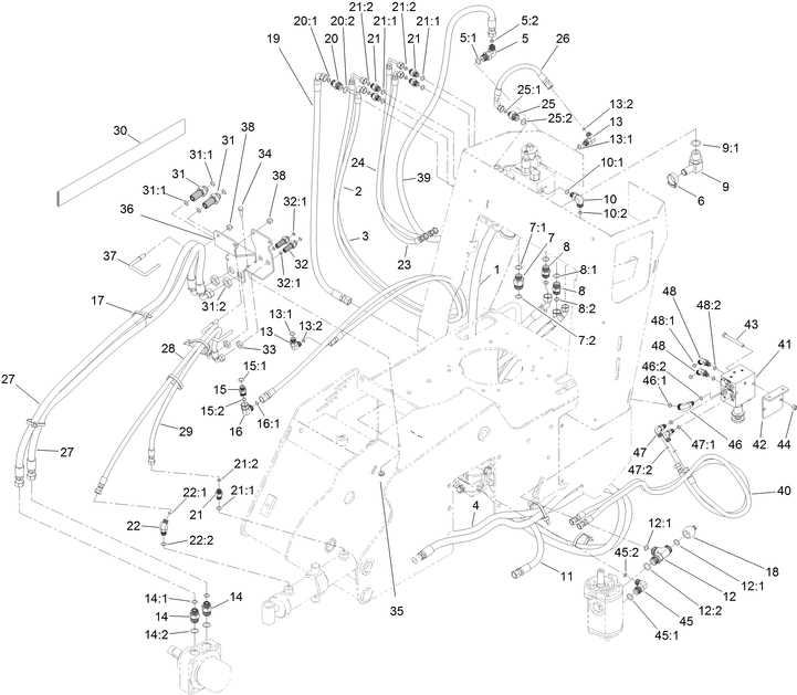
Hydraulic System Layout and Elements

The arrangement of the fluid-driven mechanisms is crucial for efficient operation. It involves various components working together to convert energy into mechanical motion, ensuring smooth and reliable functioning. Understanding the placement and interaction of these components can help in maintaining and troubleshooting the entire system.

The primary elements of this setup include a power source, transmission components, and control units. Each part plays a specific role in regulating the flow and pressure of the fluid, allowing for precise movement and force application.

Component Function Description
Pump Fluid Flow Generation Drives the fluid through the system, converting m

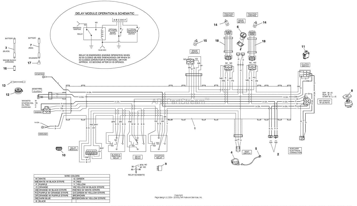
Electrical Components Breakdown for Efficient Repairs

vermeer bc1000xl parts diagram

Understanding the arrangement of key electrical elements is crucial for ensuring smooth maintenance and effective troubleshooting. Recognizing the structure of various connections, wiring routes, and control units allows for a more targeted approach when addressing electrical issues. This section highlights the core components, offering insights into their roles and typical failure points to assist in identifying potential problem areas quickly.

Among the primary elements are the control modules, which manage the interaction between different circuits. These modules often feature fuses and relays that play a vital role in protecting the system from surges and overloads. By familiarizing oneself with their placement and functions, repairs can be executed more swiftly.

Wiring harnesses form another critical aspect, connecting multiple subsystems to ensure consistent power distribution and signal transmission. Inspecting these harnesses for wear, damage, o

Cutting Mechanism Details and Adjustments

vermeer bc1000xl parts diagram

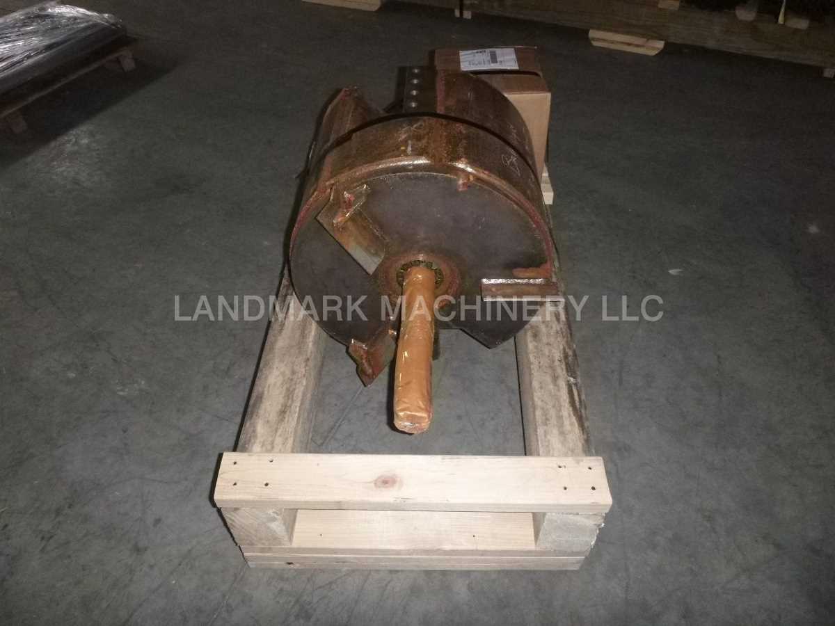
The cutting assembly plays a crucial role in the overall performance of any chipping equipment. Understanding its components and making the necessary adjustments can significantly enhance efficiency and prolong the lifespan of the machine.

Key components of the cutting assembly include:

  • Knives: Essential for the chipping process, their condition directly affects the quality of the output.
  • Housings: These provide the necessary structure and protection for the cutting tools.
  • Bearings: Critical for smooth operation, ensuring that the rotating parts function effectively.
  • Drive mechanism: Powers the cutting tools and dictates their operational speed.

Proper adjustments are necessary to maintain optimal performance. Consider the following aspects:

  1. Knife sharpness: Regularly inspect and sharpen blades to ensure effective cutting.
  2. Alignment: Ensure all components are properly aligned to minimize vibration and wear.
  3. Tension settings: Adjust the tension of the drive belts or chains to prevent slippage.
  4. Lubrication: Apply appropriate lubricants to moving parts to reduce friction and heat buildup.

Implementing these maintenance practices can lead to improved functionality and reduced downtime, ultimately contributing to more productive operations.

Safety Features and Their Locations

vermeer bc1000xl parts diagram

Ensuring the protection of operators and bystanders is paramount in machinery design. Various mechanisms are incorporated to enhance safety and minimize risks during operation. Understanding the placement and functionality of these features is crucial for effective and secure use.

Safety Feature Description Location
Emergency Stop Button Instantly halts all machine functions when activated. Front panel, easily accessible
Operator Protective Shield A barrier that shields the operator from flying debris. Surrounding the feed chute
Safety Interlock System Prevents operation when access panels are open. Near access doors and engine compartment
Warning Lights Indicates when the machine is in operation or requires attention. Control panel and rear of the machine
Reflective Safety Strips Enhances visibility of the machine in low-light conditions. Side and rear surfaces

Tips for Replacing High-Wear Parts

Maintaining equipment performance is crucial for efficiency and longevity. Regularly addressing components that experience significant wear can prevent larger issues and costly repairs. Understanding how to effectively replace these components ensures that your machinery operates at its best.

1. Schedule Regular Inspections: Conducting frequent evaluations helps identify worn components early. Make it a routine to check critical areas to spot any signs of degradation before they lead to failure.

2. Use Quality Replacements: Always opt for high-quality replacements that meet or exceed manufacturer specifications. Using subpar alternatives can result in decreased performance and shorter lifespan.

3. Follow Manufacturer Guidelines: Adhering to recommended procedures for component replacement is vital. This includes following specific torque specifications and installation techniques to ensure proper function.

4. Keep a Maintenance Log: Documenting all maintenance activities, including replacements, assists in tracking wear patterns. This information can be invaluable for future troubleshooting and planning.

5. Ensure Proper Tooling: Utilizing the correct tools for replacement tasks is essential. Using improper tools can damage components or lead to unsafe operating conditions.

6. Train Operators: Providing training for operators on recognizing wear indicators and performing basic maintenance can extend the life of machinery. An informed team can take proactive measures to mitigate wear.

7. Dispose of Old Components Responsibly: Proper disposal of old components is important for environmental sustainability. Follow local regulations for recycling or disposing of worn parts.