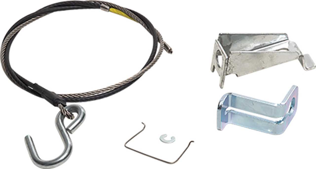
In the realm of engineering and manufacturing, visual representations play a crucial role in the successful assembly and maintenance of complex systems. These graphical illustrations serve as essential guides, enabling technicians and engineers to navigate through intricate structures with ease. By breaking down each element, these representations provide clarity and enhance understanding, ultimately streamlining the production process.
Detailed layouts allow for the identification of individual elements and their respective functions within the overall system. Such clarity ensures that every component is correctly positioned and securely fastened, minimizing the risk of errors during assembly. Moreover, these visual aids facilitate effective communication among team members, fostering collaboration and enhancing overall project efficiency.
Whether you are a seasoned professional or a novice in the field, grasping the intricacies of these visual guides can significantly impact the success of your projects. By delving into the nuances of component arrangement, one can unlock the full potential of any system, paving the way for innovation and excellence in design and functionality.
Understanding UFP A-60 Components
This section delves into the essential elements of a specific model, exploring their functions and interrelations. Each component plays a vital role in the overall performance, contributing to efficiency and reliability. By examining these parts, one can gain a clearer understanding of how they work together to achieve optimal functionality.
Key Elements Overview
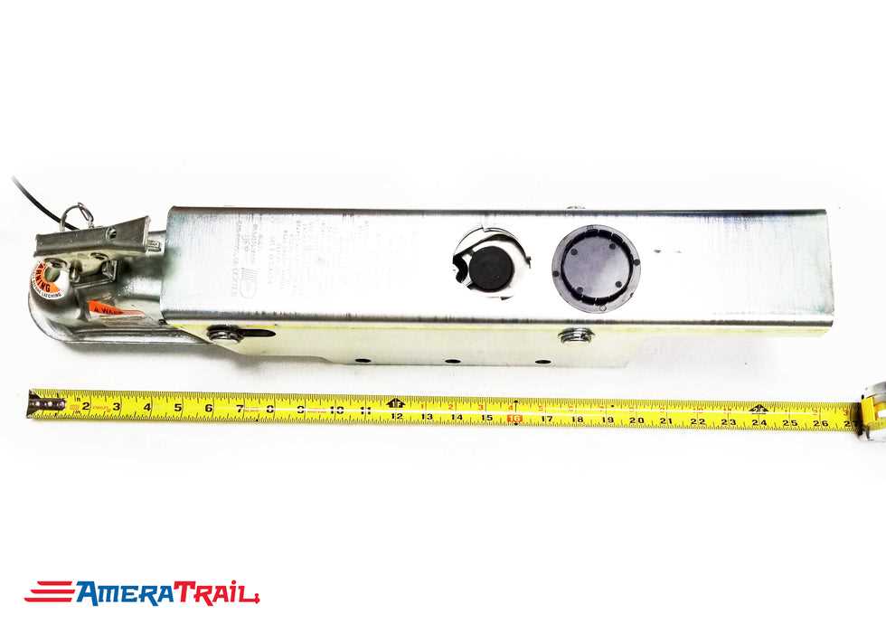
Analyzing the main components reveals a complex yet organized structure. Each part is designed to fulfill a specific task, ensuring that the system operates smoothly. From the foundational units to the intricate mechanisms, understanding their roles can enhance maintenance and troubleshooting efforts.
Component Functionality Table
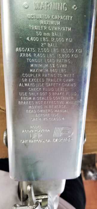
| Component Name | Description | Function |
|---|---|---|
| Element A | Primary unit responsible for initialization | Activates the system |
| Element B | Supporting structure enhancing stability | Provides structural integrity |
| Element C | Control interface for user interaction | Facilitates user commands |
| Element D | Energy supply module | Powers the entire system |
Overview of UFP A-60 Parts
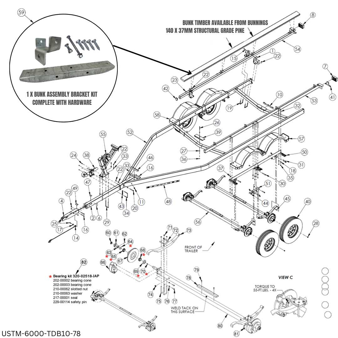
This section delves into the essential components that make up the intricate assembly of the model in question. Understanding these elements is crucial for both maintenance and enhancement purposes, allowing users to maximize the efficiency and longevity of the device. Each component plays a specific role, contributing to the overall functionality and performance.
Key Components and Their Functions
The primary elements include the structural framework, which provides stability and support, and the operational mechanisms, which ensure seamless performance. Additionally, electronic systems are integrated to facilitate control and monitoring, enhancing user interaction and safety. Each part is designed to work in harmony with the others, reflecting a thoughtful engineering process.
Importance of Component Quality
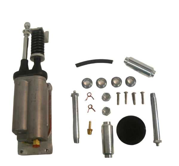
The quality of these individual elements directly impacts the reliability and effectiveness of the entire assembly. Using high-grade materials and precise manufacturing techniques is vital to ensure that each component withstands operational demands and environmental conditions. Regular assessment and potential upgrades can further improve performance and user satisfaction.
Importance of Accurate Diagrams
Precision in visual representations plays a crucial role in various fields, ensuring that complex systems are understood and maintained effectively. These illustrations serve as essential tools for communication, enabling individuals to grasp intricate relationships and components within a structure. Accurate visualizations help prevent misunderstandings that could lead to costly errors or inefficient operations.
Moreover, detailed visuals contribute to enhanced training and onboarding processes. New team members can quickly familiarize themselves with the layout and functioning of systems, thereby accelerating their productivity. This clarity not only streamlines workflow but also fosters a collaborative environment where everyone can contribute more effectively.
In addition, relying on exact representations facilitates troubleshooting and repairs. When issues arise, having clear and precise visuals allows technicians to identify problems swiftly, minimizing downtime and resource wastage. Ultimately, the reliability of these graphics underpins the overall efficiency and safety of operations, making them indispensable in any technical context.
Common Issues with UFP A-60 Parts
When dealing with specific components, various challenges can arise that impact functionality and longevity. Identifying these common problems can help in ensuring optimal performance and timely maintenance.
One prevalent issue is:
- Wear and Tear: Over time, regular usage can lead to degradation, affecting the efficiency of individual elements.
Another frequent concern involves:
- Compatibility: Some components may not fit well with other system parts, leading to operational inefficiencies.
Additionally, users often face:
- Installation Errors: Improper setup can cause malfunctioning or even damage, underscoring the importance of following guidelines.
Regular maintenance can help mitigate these issues, but awareness of potential pitfalls is crucial for ensuring the longevity and effectiveness of the components involved.
Maintenance Tips for UFP A-60
Regular upkeep is essential for ensuring optimal performance and longevity of your equipment. Proper care not only enhances efficiency but also reduces the likelihood of costly repairs. Here are some effective strategies to maintain your device effectively.
Routine Checks
- Inspect all components for signs of wear or damage.
- Check connections and ensure they are secure.
- Clean surfaces to prevent buildup of debris.
Lubrication and Cleaning
- Apply lubricant to moving parts regularly to minimize friction.
- Use a soft cloth to wipe down the exterior, removing dust and grime.
- Ensure that any filters are replaced or cleaned according to the manufacturer’s guidelines.
By following these maintenance tips, you can ensure that your equipment remains in top condition, providing reliable service for years to come.
Where to Find Replacement Parts
Locating suitable components for your equipment can be a straightforward process if you know where to look. Various sources offer a range of options, ensuring that you can find what you need without much hassle. From online retailers to specialized local shops, each avenue presents unique benefits for obtaining quality items.
Online Marketplaces: Numerous websites cater to those seeking specific components. Major e-commerce platforms often have vast selections, allowing users to compare prices and read reviews to make informed decisions. Additionally, many manufacturers maintain their own websites, offering direct purchasing options for genuine items.
Local Retailers: Don’t overlook nearby stores, especially those specializing in hardware or mechanical supplies. They can provide personalized assistance, and you might find items that are not listed online. Establishing a relationship with these retailers can also lead to recommendations for other local resources.
Forums and Community Groups: Online communities and discussion boards can be invaluable for advice and sourcing suggestions. Members often share experiences, including where to find specific components and may even have leads on second-hand options that are in good condition.
Salvage Yards and Recycling Centers: Exploring salvage yards can uncover hidden gems. These locations frequently have various mechanical components that can be refurbished or repurposed. It’s an eco-friendly option that often comes at a lower cost than brand-new items.
By utilizing these resources, you can efficiently find the necessary replacements for your equipment, ensuring it continues to operate smoothly.
Visual Aids for Assembly Process
Utilizing visual resources can significantly enhance the efficiency and accuracy of the assembly workflow. These tools provide clear guidance, streamline communication, and reduce the likelihood of errors during the construction phase. By incorporating illustrations, schematics, and other graphical elements, teams can improve their understanding of complex tasks and ensure consistency in the final output.
Benefits of Visual Aids
- Improved Clarity: Visual representations simplify complex instructions, making it easier for workers to grasp the necessary steps.
- Enhanced Communication: Illustrations can bridge language barriers, ensuring that all team members are on the same page.
- Reduced Errors: Clear visuals help minimize misunderstandings, leading to fewer mistakes in assembly.
- Time Efficiency: Quick reference guides allow for faster training and onboarding of new personnel.
Types of Visual Resources
- Flowcharts: These diagrams outline the sequential steps in the assembly process, providing a roadmap for workers.
- Exploded Views: These illustrations depict components separated from each other, clarifying how parts fit together.
- Photographic Guides: High-quality images of the assembly stages offer real-world references to assist in proper execution.
- Checklists: Visual checklists ensure that all steps are completed in the correct order, enhancing accountability.
Comparative Analysis of Similar Models
This section delves into a comparative examination of analogous units within the same category, highlighting their functionalities, structural components, and user experiences. Understanding the distinctions and similarities among these models can aid in making informed decisions for potential users and buyers.
In the table below, we present key specifications and features of three comparable models. This will provide a clearer perspective on how they stack up against one another in various aspects such as performance, efficiency, and design.
| Model | Performance | Efficiency Rating | Key Features | Price |
|---|---|---|---|---|
| Model A | High | A+ | Compact design, quick setup, energy-saving mode | $200 |
| Model B | Medium | B | User-friendly interface, durable materials | $150 |
| Model C | High | A | Advanced technology, wireless connectivity | $250 |
By analyzing the features and pricing, potential customers can discern which model best suits their needs, considering both budgetary constraints and desired functionalities. This comparative analysis serves as a valuable resource for anyone seeking to navigate the options available in the marketplace.
User Experiences and Feedback
This section delves into the perspectives and insights shared by individuals who have engaged with the product. Their testimonials and evaluations offer valuable information regarding functionality, usability, and overall satisfaction. By examining user comments, potential buyers can better understand the strengths and weaknesses of the item in question.
Positive Feedback
Many users highlight several aspects they appreciate about the product:
- Ease of assembly and setup
- Durability and reliability over time
- Clear instructions and guidance provided
- Exceptional customer support experience
Areas for Improvement
Despite the positive feedback, some users have pointed out areas that could benefit from enhancements:
- Increased clarity in the user manual
- Better compatibility with various accessories
- Improvements in certain features for enhanced performance
Overall, user experiences provide a comprehensive view that can assist future customers in making informed decisions.