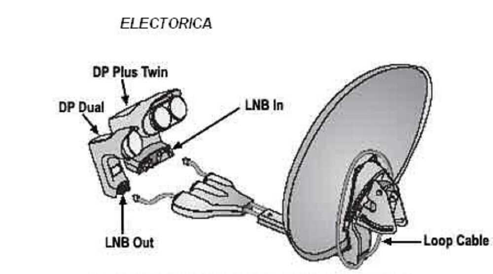
The ability to capture signals from distant transmitters relies on specialized equipment designed to focus and amplify these transmissions. Understanding how such systems work involves examining the core elements that make up the receiver. These components work together to ensure proper signal reception, amplification, and clarity, offering users a reliable connection to various broadcasts.
In this guide, we’ll break down the individual elements that are integral to a well-functioning receiver system. Each part has a distinct role, contributing to the overall efficiency and effectiveness of the setup. By gaining a clear understanding of how these pieces interact, you can ensure optimal performance and even troubleshoot common issues.
Whether you are setting up a new system or maintaining an existing one, knowing the essential elements is crucial for both performance and longevity. Let’s take a closer look at these core components, offering insights into their functions and how they contribute to the broader system.
Understanding the Components of a Satellite Dish

The functionality of a signal receiver relies on various interconnected elements that work together to capture and transmit data effectively. Each element plays a crucial role in ensuring optimal performance, allowing for the reception of clear and stable transmissions.
Main Reflector
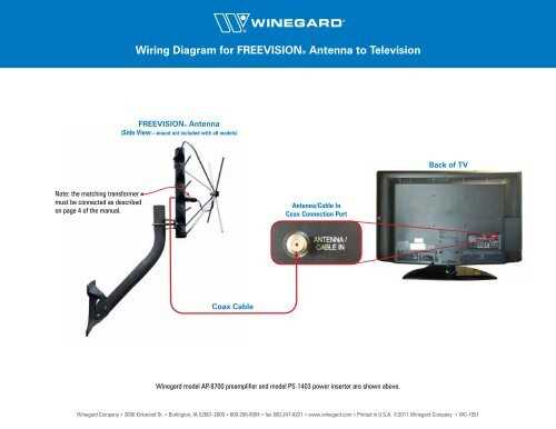
The largest component is a curved surface designed to collect signals from space and redirect them toward a central point. Its concave shape ensures that the waves are concentrated, enhancing the overall efficiency of signal reception.
Feedhorn and LNB
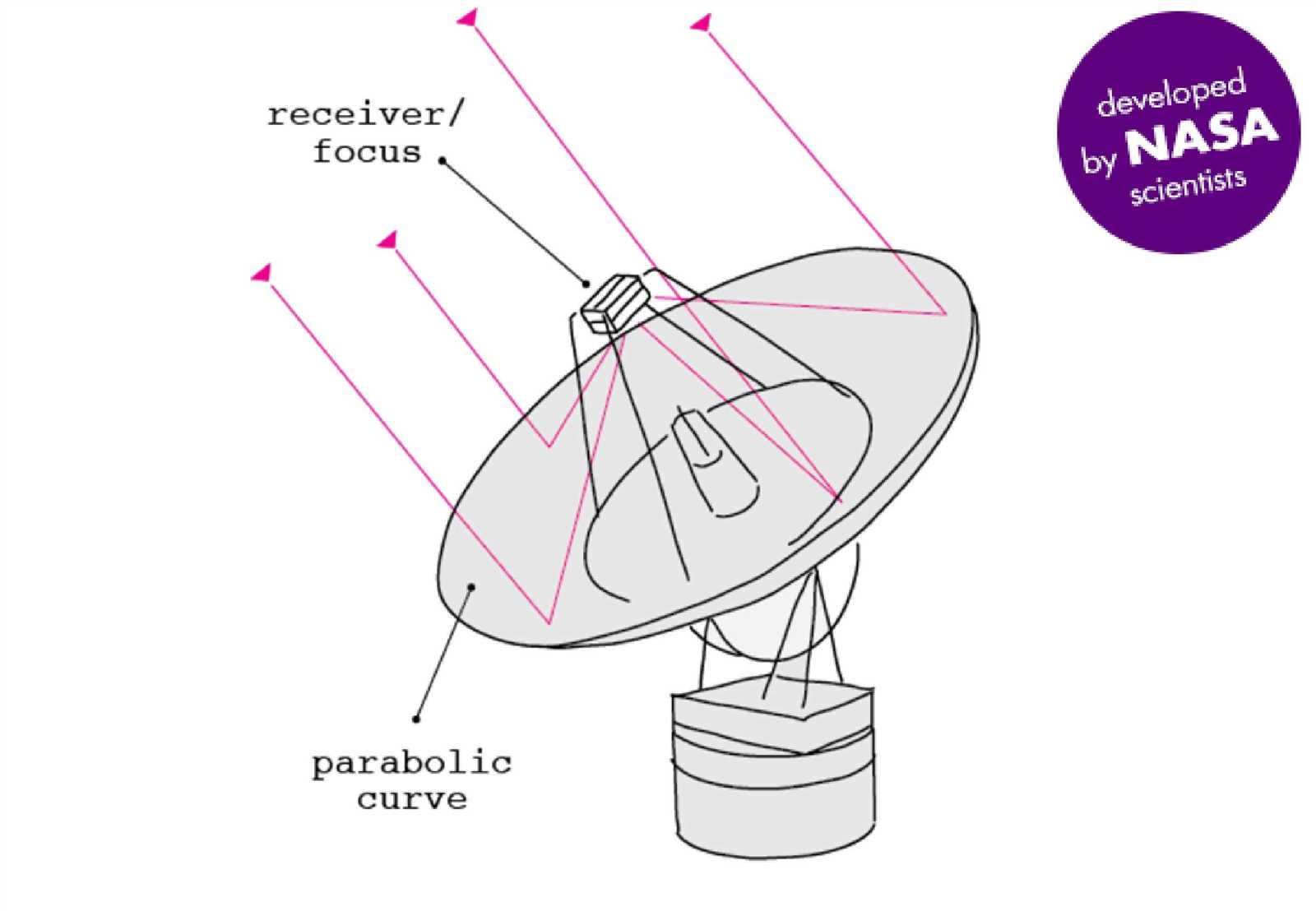
At the focal point of the reflector, the feedhorn directs incoming waves to a specialized device known as the Low Noise Block (LNB). The LNB amplifies the weak signals and converts them into a lower frequency, making them easier to process and transmit to the receiver.
Support Structures like arms and mounts are critical for maintaining the proper alignment and stability of the entire setup. These components ensure the system remains accurately pointed to its source, even in challenging weather conditions.
Main Reflector: The Heart of the Dish

The central component of this technology is crucial for capturing and directing signals effectively. It ensures the proper alignment and concentration of energy to achieve optimal performance. Without this essential structure, signal quality and reception would be significantly compromised.
Design and Function
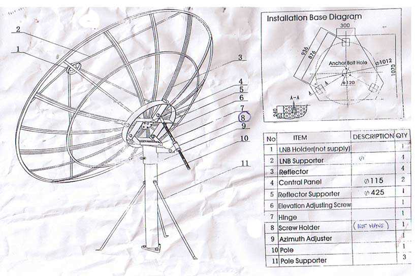
The primary element is typically shaped to enhance the focus of incoming signals. Its concave form is engineered to reflect and concentrate these signals toward the focal point. This design allows for precision and ensures maximum efficiency in signal capture.
- Reflects signals towards a specific point
- Designed with a curvature to enhance focus
- Made from materials that minimize signal loss
Material Composition
Manufacturers use materials that are both durable and efficient in signal reflection. Commonly, lightweight metals or composites are chosen to provide a balance between strength and performance, ensuring the long-term durability of the structure.
- Aluminum for lightweight and rust resistance
- Composite materials for enhanced durability
- Special coatings to improve reflectivity
Feed Horn: Capturing the Signal

The feed horn plays a vital role in the reception of signals from a distant source. Positioned at the focal point of the system, it is responsible for guiding the incoming wave to a central processing unit. This component is crucial for ensuring that signals are properly concentrated and directed for further interpretation.
How the Feed Horn Works
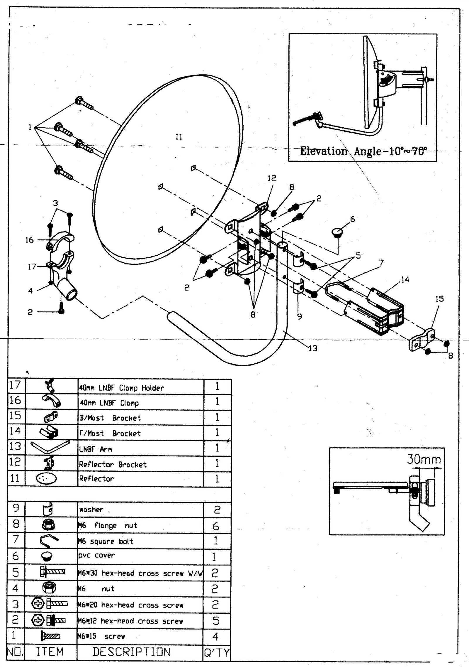
The feed horn collects the electromagnetic waves and channels them efficiently. Its design allows for minimal loss during signal transfer, ensuring that the waves reach the next stage of the receiver with maximum strength. This process is essential for clear and accurate communication reception.
Key Features of a Feed Horn
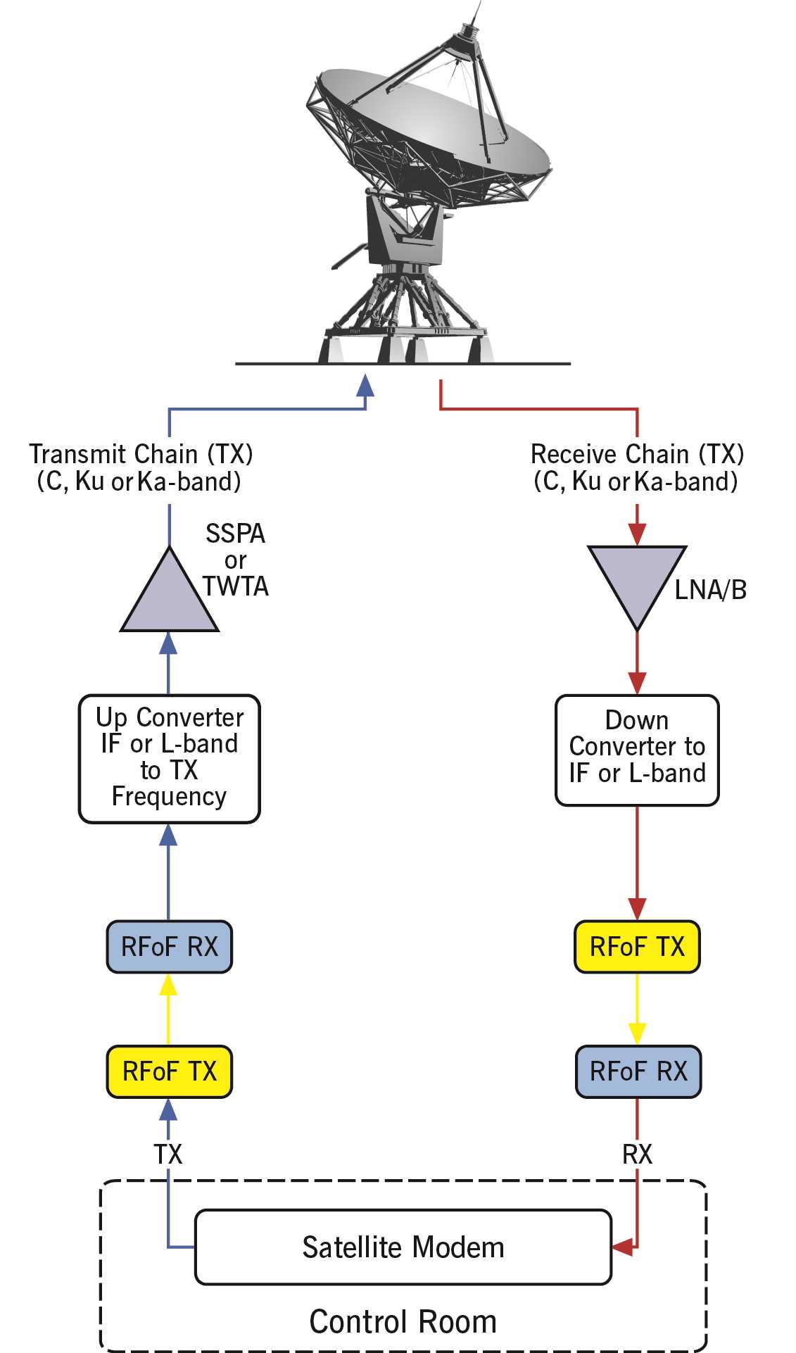
- Optimized for high-frequency signals.
- Engineered to reduce noise and interference.
- Designed for efficient signal concentration and transmission.
In combination with other elements, the feed horn enhances the clarity and reliability of the received transmission, making it an indispensable part of modern communication technology.
Low Noise Block (LNB) Converter Explained
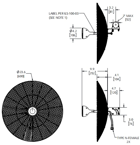
A Low Noise Block (LNB) converter is a key component in receiving signals from distant transmitters. Its primary role is to convert high-frequency signals into a lower frequency range that can be processed by receiving equipment. This conversion is essential for stable and effective communication. Without this crucial element, efficient signal reception would be challenging.
How an LNB Works
The LNB receives incoming waves and amplifies them while reducing noise interference. It then shifts the frequency of the signal to a more manageable range. This process ensures that signals remain strong and clear even when they travel long distances. By optimizing signal quality, the LNB plays a fundamental role in maintaining reliable communication links.
Key Features of LNB
| Feature |
Description |
| Frequency Conversion |
Transforms high-frequency signals into lower frequencies for easier transmission. |
| Noise Reduction |
Minimizes background noise to improve signal clarity and strength. |
| Signal Amplification |
Boosts weak signals, ensuring they reach the receiver with minimal loss. |
Support Arm and Its Purpose
The support arm plays a crucial role in ensuring the stability and alignment of the entire structure. It serves as a fundamental element, maintaining the correct positioning and enabling the system to function efficiently over time. Its design is engineered to bear the weight and withstand external forces, while preserving optimal performance.
One of the main functions of this component is to hold and secure various elements in place, allowing them to operate seamlessly. Without the support arm, proper alignment would be compromised, leading to reduced accuracy and potential malfunctions in the system.
In addition to providing physical stability, the support arm is often designed with adjustable features to fine-tune the overall setup. This adjustability allows for precision in alignment, further enhancing the effectiveness of the entire configuration. Its purpose goes beyond mere support, as it also contributes to the longevity and durability of the setup.
Mounting Brackets: Stability and Adjustment
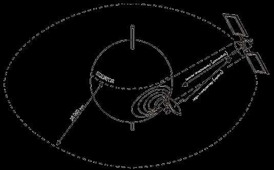
Properly securing the components is essential for optimal functionality and performance. The support structures play a crucial role in ensuring that the entire assembly remains stable, preventing any unnecessary movement or vibrations. This section will discuss the importance of these supports and how adjustments can enhance the setup.
- Types of Mounting Supports:
- Wall brackets
- Pole mounts
- Roof mounts
- Stability Considerations:
- Material strength: Choose durable materials to withstand environmental factors.
- Proper alignment: Ensure correct positioning to avoid unnecessary stress.
- Secure fastening: Use appropriate hardware to maintain a tight connection.
- Adjustment Techniques:
- Fine-tuning angles for optimal signal reception.
- Leveling adjustments to accommodate uneven surfaces.
- Height modifications to achieve desired elevation.
Utilizing high-quality support structures and employing precise adjustment techniques significantly contributes to the overall effectiveness of the installation. By paying attention to these details, users can ensure reliable performance and longevity of their setup.
Azimuth and Elevation Control Mechanisms
The alignment and positioning of receiving equipment play a crucial role in optimizing signal reception. Understanding how to effectively adjust the angles of orientation is essential for achieving the best performance. This section explores the mechanisms involved in controlling horizontal and vertical angles.
To achieve optimal signal quality, two primary adjustments are necessary:
- Azimuth Adjustment: This involves rotating the assembly along the horizontal plane. Proper azimuth control allows users to align the equipment accurately towards the source.
- Elevation Adjustment: This mechanism adjusts the angle in the vertical plane. Elevation control is vital for fine-tuning the position, enabling a direct line of sight to the transmitting source.
The following components are commonly associated with these control mechanisms:
- Mounting Bracket: This supports the entire setup and facilitates movement along both axes.
- Gimbals: These allow for smooth rotation and stabilization when adjusting angles.
- Drive Motors: These are used to automate the adjustment process, enhancing precision and ease of use.
- Control Interface: This may be a manual or digital system that provides users with the means to make necessary adjustments effectively.
In conclusion, mastering the control mechanisms for orientation angles is essential for maximizing reception quality and ensuring reliable performance. Understanding how each component contributes to the overall functionality is key for both installation and operation.
Coaxial Cable: The Signal Pathway
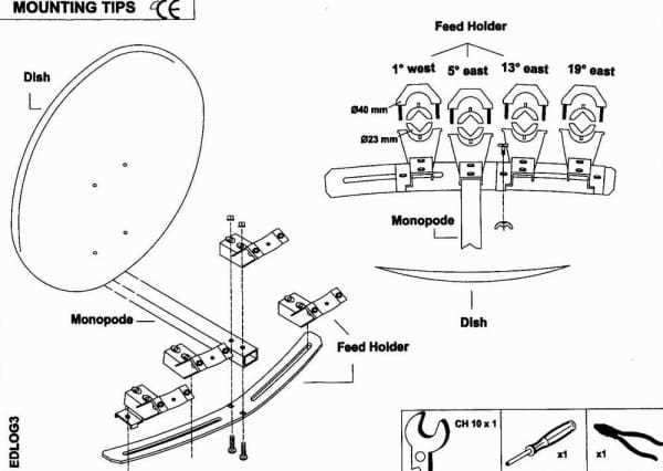
The coaxial cable serves as a vital conduit for transmitting information between various components of a communication system. Its design and functionality ensure minimal interference while delivering high-quality signals. This section explores the significance of this cable in effective data transfer and its role in maintaining signal integrity.
Constructed with a central conductor, dielectric insulation, and an outer conductive shield, the coaxial cable is engineered to protect the signal traveling within. This layered architecture enhances performance and reduces the risk of external noise disrupting the transmission.
- Central Conductor: The inner wire responsible for carrying the electrical signals.
- Dielectric Insulation: The non-conductive material surrounding the conductor, which prevents short circuits and ensures signal clarity.
- Outer Shield: A conductive layer that protects against electromagnetic interference and physical damage.
When installed correctly, this type of cable can efficiently deliver signals over considerable distances without significant loss. Its applications are diverse, ranging from television broadcasting to internet connectivity.
Key benefits include:
- High resistance to signal degradation.
- Versatility in various communication systems.
- Ease of installation and handling.
Overall, the coaxial cable remains a fundamental element in modern communication networks, ensuring reliable signal delivery and enhancing user experience.
Weatherproofing and Protection Measures
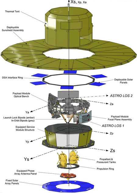
Ensuring the longevity and optimal performance of outdoor equipment requires effective weatherproofing and protective strategies. Environmental factors such as moisture, wind, and extreme temperatures can significantly impact functionality and durability. Implementing appropriate measures not only safeguards the components but also enhances reliability and performance over time.
Sealing and Insulation
Utilizing high-quality sealants and insulating materials is crucial for minimizing water ingress and protecting against moisture buildup. Weather-resistant sealants can be applied to joints and connections, creating a barrier against rain and humidity. Additionally, insulation wraps can be employed to shield sensitive components from temperature fluctuations, preventing damage from freezing or overheating.
Structural Support and Positioning
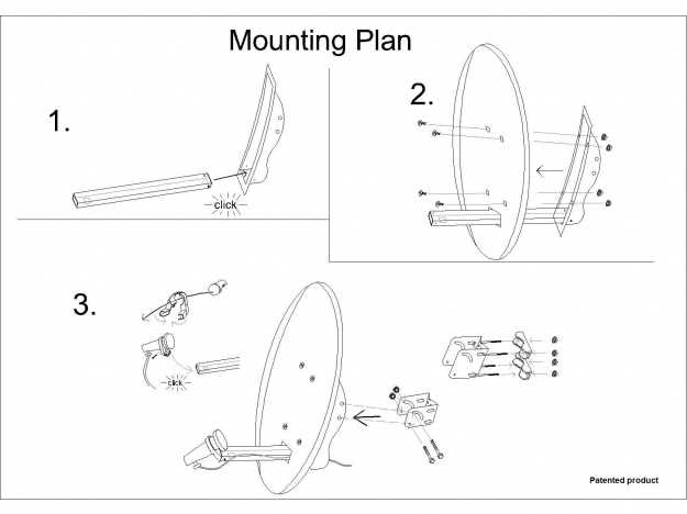
Proper positioning and structural support are essential for maintaining stability in adverse weather conditions. Installing equipment on a sturdy mount and ensuring it is securely anchored can help prevent movement and damage from strong winds. Furthermore, orienting the setup to avoid direct exposure to harsh weather elements can enhance its resilience, contributing to a longer service life.


