When it comes to maintaining or repairing a power device, having a clear view of its internal arrangement can be immensely helpful. Knowing how different components interact with each other allows for efficient troubleshooting and ensures that each part functions optimally. A structured layout serves as a guide, helping users navigate through the intricate assembly.
Identifying the specific elements and their locations within the device is crucial for both routine upkeep and more complex repairs. It simplifies the process of locating necessary components, whether for cleaning, replacement, or enhancement. This approach ensures that even those without extensive technical expertise can manage essential maintenance tasks with greater ease.
Moreover, an organized view of the internal structure aids in understanding how each segment contributes to the device’s overall performance. Recognizing these interconnections provides valuable insights that can help in optimizing operation and extending the life of the machine. Such clarity is beneficial not only for immediate needs but also for long-term care and upgrades.
Key Components and Functions
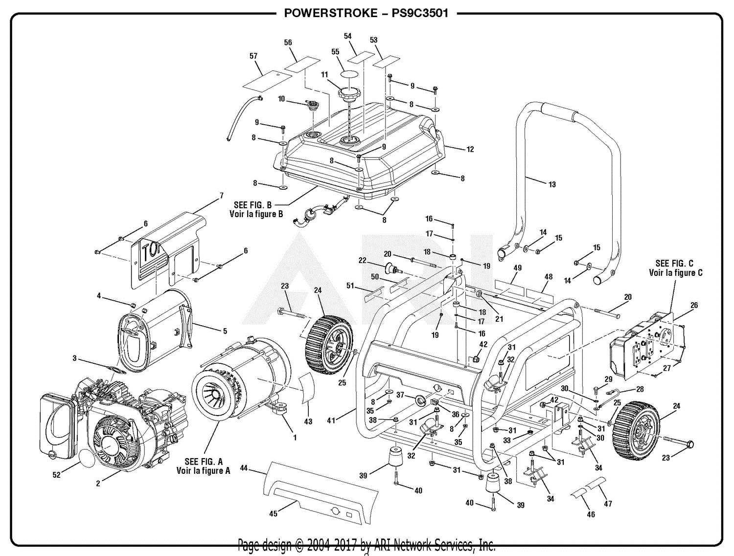
This section focuses on the essential elements and their roles within the energy-producing device. Understanding these components is crucial for effective maintenance and optimal performance.
The primary elements can be categorized into several key functions:
- Power Source: The core element responsible for generating electricity, converting fuel into usable energy.
- Control Panel: The interface that allows users to monitor and manage the device’s operations, including starting and stopping mechanisms.
- Cooling System: A vital feature that prevents overheating by dissipating excess heat generated during operation.
- Fuel System: Comprises components that store and deliver fuel to the engine, ensuring efficient combustion.
- Exhaust System: Responsible for directing harmful gases away from the machine and improving air quality during operation.
Each component plays a specific role that contributes to the overall functionality and efficiency of the machine. Regular inspection and maintenance of these elements can enhance reliability and longevity.
Engine Assembly and Maintenance Tips
Proper assembly and regular maintenance of your power source are essential for optimal performance and longevity. Understanding the critical components and how they interact will help ensure smooth operation. By following recommended practices, you can enhance efficiency and reduce the likelihood of issues arising over time.
When assembling the engine, ensure that all components are clean and free from debris. Pay special attention to the alignment of parts, as misalignment can lead to premature wear and potential failure. Use appropriate tools to avoid damaging sensitive components during assembly.
| Maintenance Task | Frequency | Tips |
|---|---|---|
| Oil Change | Every 50 hours | Use the recommended oil type for optimal performance. |
| Air Filter Inspection | Every 25 hours | Clean or replace the filter to ensure proper airflow. |
| Fuel System Check | Monthly | Inspect for leaks and ensure fuel is fresh. |
| Spark Plug Replacement | Every 100 hours | Check for wear and replace as necessary to maintain ignition. |
Following these guidelines will help maintain the integrity of the engine and enhance its performance. Regular inspections and timely replacements can prevent costly repairs and downtime.
Electrical Wiring and Connections Guide
This section provides a comprehensive overview of the electrical connections and wiring essential for the optimal functioning of your device. Understanding these components is crucial for effective assembly, troubleshooting, and maintenance. Proper wiring ensures safety, efficiency, and longevity, making this guide an invaluable resource.
Key Components of Electrical Connections
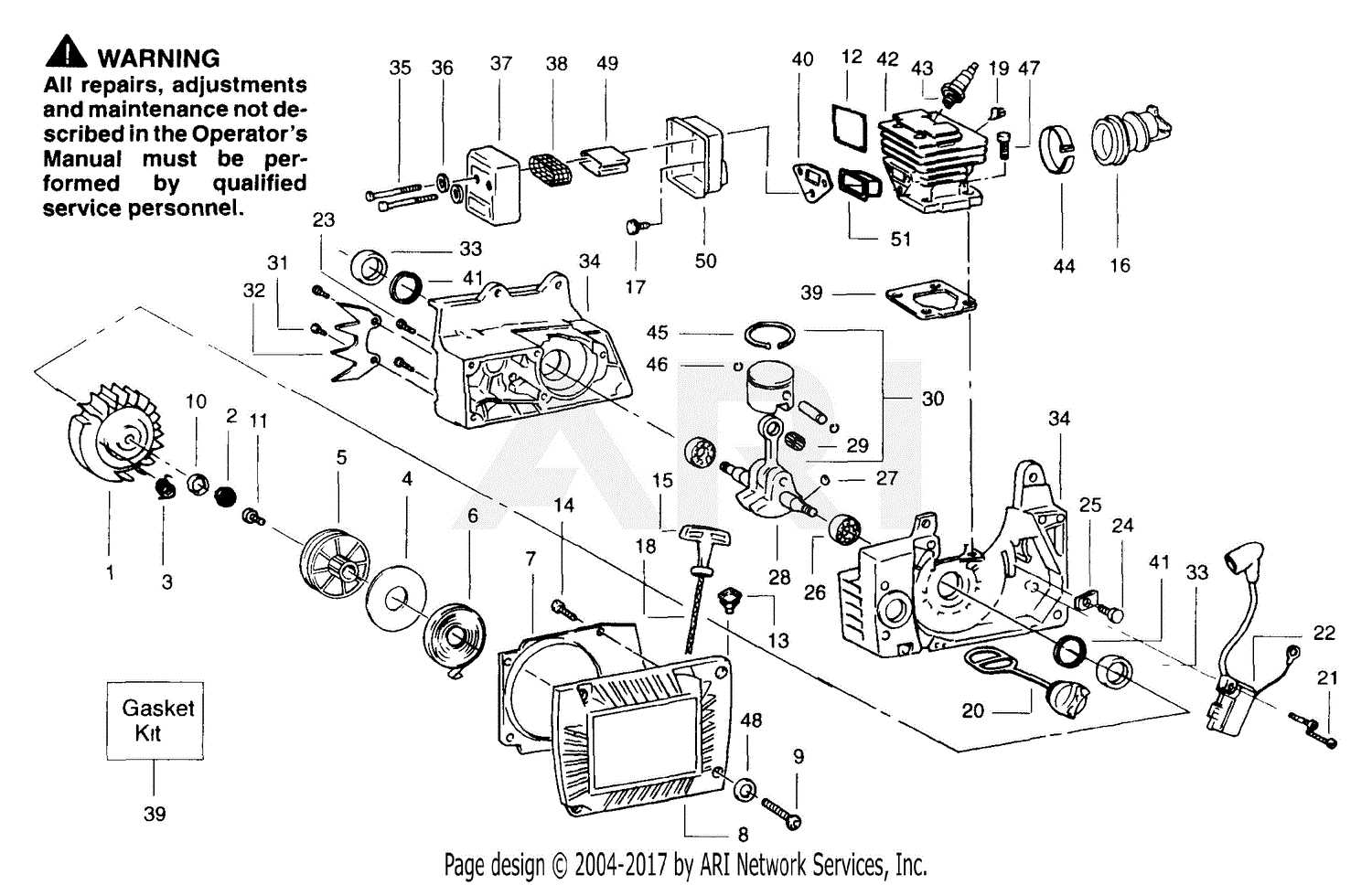
- Wires: Conductors that transmit electricity between various components.
- Connectors: Join wires securely to prevent disconnection or short circuits.
- Fuses: Protect the circuit by breaking the connection in case of overload.
- Switches: Control the flow of electricity, allowing you to turn the device on and off.
Steps for Proper Wiring
- Gather all necessary tools and components for assembly.
- Identify the wiring layout as per the manufacturer’s instructions.
- Connect wires to their respective terminals, ensuring a secure fit.
- Test each connection for continuity before finalizing the setup.
- Secure any loose wires and ensure they are properly insulated.
Following these guidelines will enhance the reliability of your electrical system, reducing the risk of faults and ensuring efficient performance.
Fuel System Parts Identification
The fuel system is a crucial component of any engine, responsible for delivering the necessary fuel to ensure optimal performance. Understanding the different elements involved can help users diagnose issues and maintain efficiency. This section outlines the key components typically found in these systems.
- Fuel Tank: The reservoir that holds the fuel before it is sent to the engine.
- Fuel Pump: A device that moves fuel from the tank to the engine, ensuring a steady flow.
- Fuel Filter: This component removes impurities from the fuel, protecting the engine from damage.
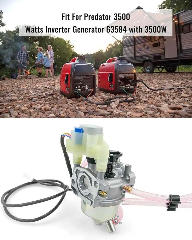
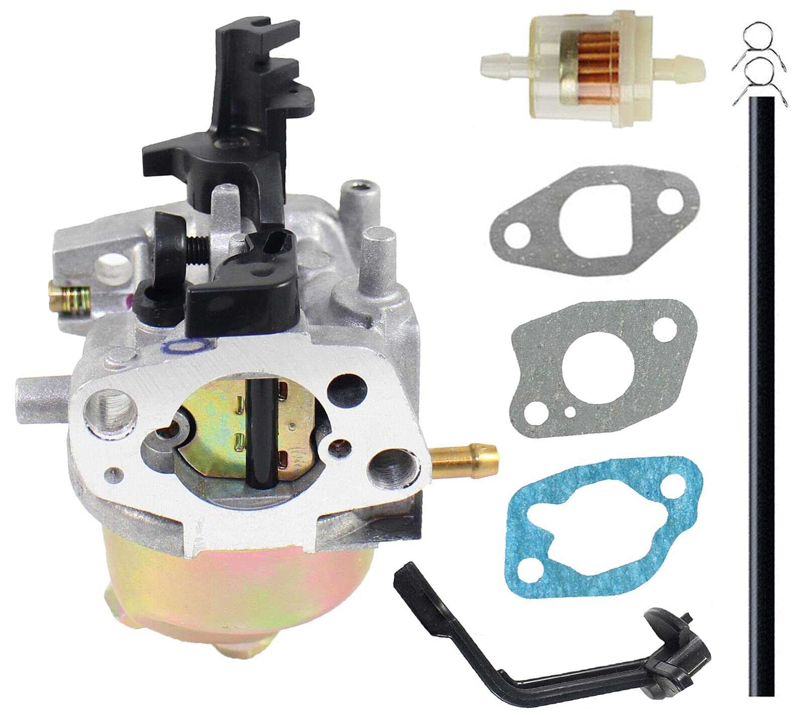
- Carburetor: Responsible for mixing fuel with air in the correct ratio for combustion.
- Fuel Lines: Hoses that transport fuel between the tank, pump, filter, and engine.
- Choke: A mechanism that controls the amount of air entering the carburetor, assisting in cold starts.
Familiarizing oneself with these components can facilitate effective troubleshooting and maintenance of the fuel delivery system, ultimately enhancing the longevity and reliability of the engine.
Cooling System Structure and Care
The cooling mechanism of any engine is vital for its optimal performance and longevity. It ensures that the engine does not overheat, maintaining the right operating temperature during use. Understanding the components and their functions can significantly enhance maintenance practices and improve the unit’s efficiency.
Components of the Cooling Mechanism
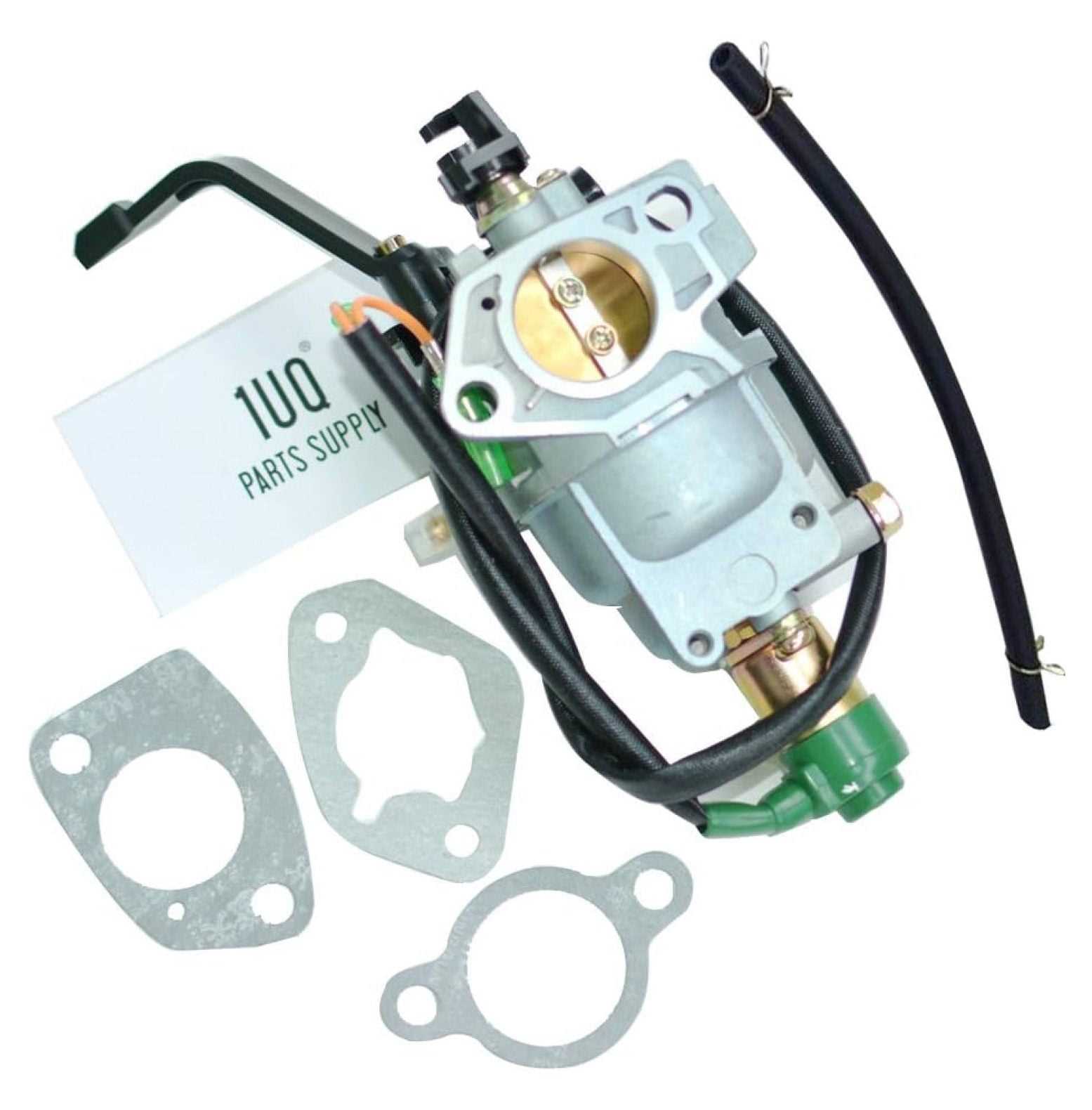
The cooling system consists of several essential parts that work together to regulate temperature:
- Radiator: This component dissipates heat from the coolant as it circulates through the system.
- Water Pump: It circulates the coolant through the engine and radiator, ensuring consistent flow.
- Thermostat: This device regulates the coolant flow based on the engine temperature, allowing for efficient operation.
- Cooling Fan: It enhances air circulation through the radiator, especially during low-speed operations.
Maintenance Tips for the Cooling System
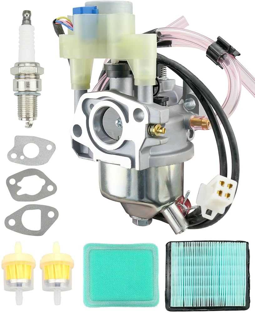
Regular care of the cooling mechanism is crucial to prevent overheating and engine damage. Here are some best practices:
- Check the coolant level regularly to ensure it is within the recommended range.
- Inspect hoses and connections for leaks or wear to maintain proper circulation.
- Flush the cooling system periodically to remove any sediment or corrosion buildup.
- Ensure the radiator is clean and free from debris to optimize airflow.
- Test the thermostat function to guarantee it opens and closes properly at the designated temperatures.
Control Panel Parts and Features
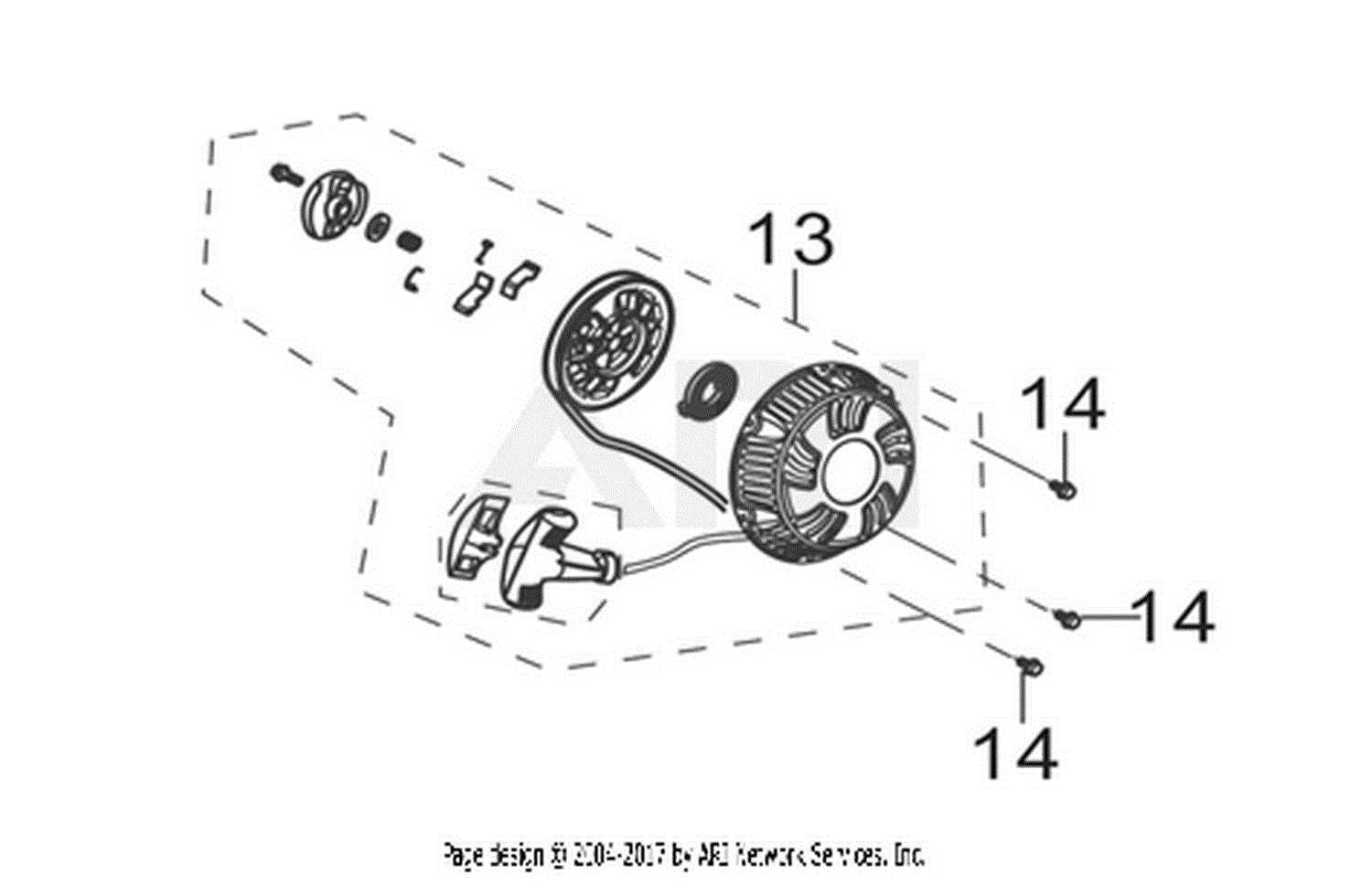
The control panel of a power-producing device is a vital component that serves as the interface for the user. It consolidates essential controls and indicators, allowing for seamless operation and monitoring of the machine’s performance. Understanding the various elements of the control panel is crucial for effective usage and maintenance.
Key Components
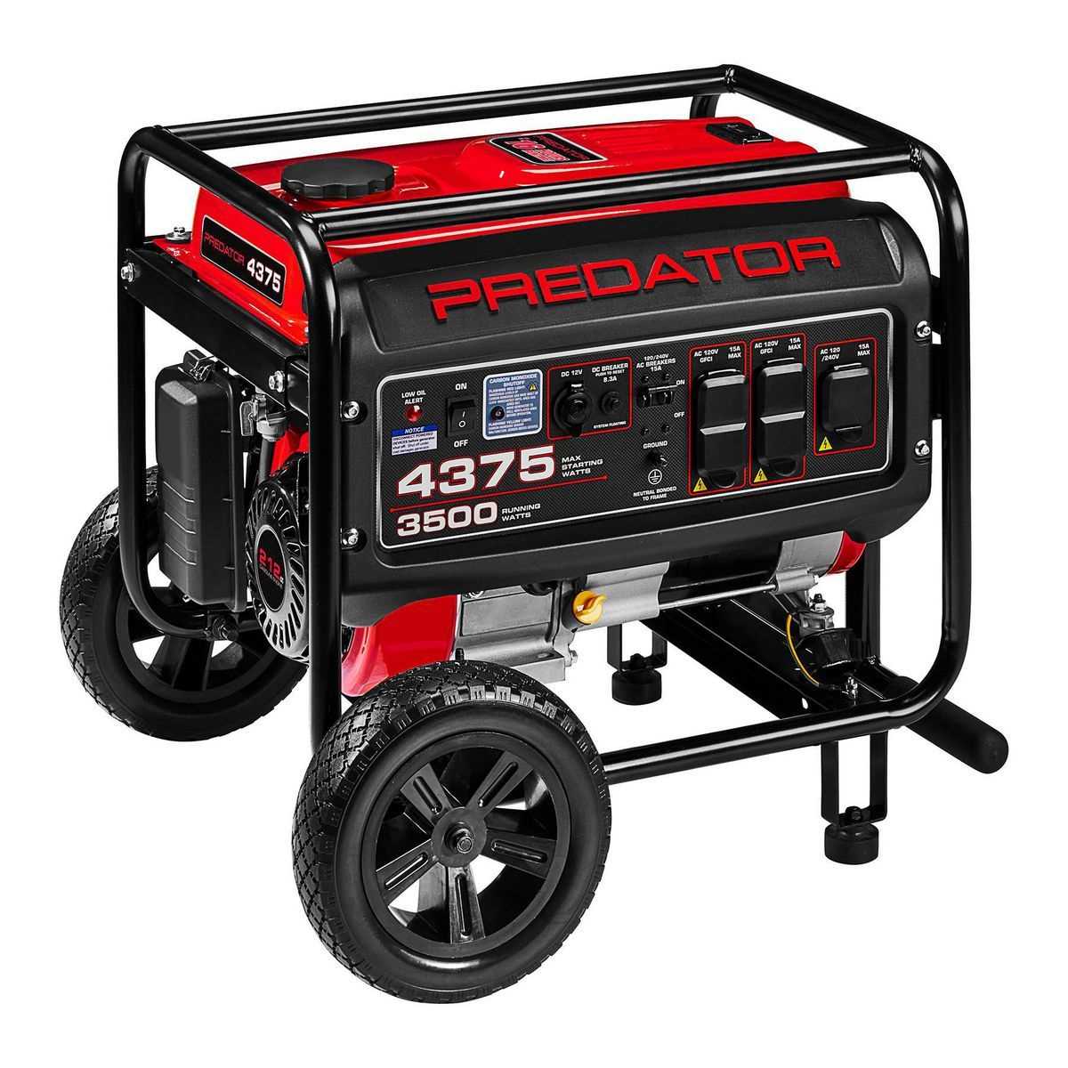
The main elements typically found on the control panel include switches, meters, and outlets. Switches enable users to start and stop the device, while meters provide real-time information regarding voltage, frequency, and operational status. Outlets allow for the connection of various electrical devices, ensuring versatility and convenience.
Functionality and Importance
Each feature on the control panel is designed to enhance usability and safety. For instance, an overload indicator alerts users to potential issues, preventing damage to the equipment. Additionally, intuitive layout and labeling of controls simplify operation, making it accessible for users with varying levels of expertise.
Frame and Mounting Hardware Details
The framework and mounting components of any portable energy supply device play a crucial role in its stability and overall performance. A robust frame ensures that the machinery remains securely in place during operation, while the mounting hardware provides essential support, allowing for easy transport and setup. Understanding the specific elements involved in this system can enhance both functionality and longevity.
Key Components of the Framework
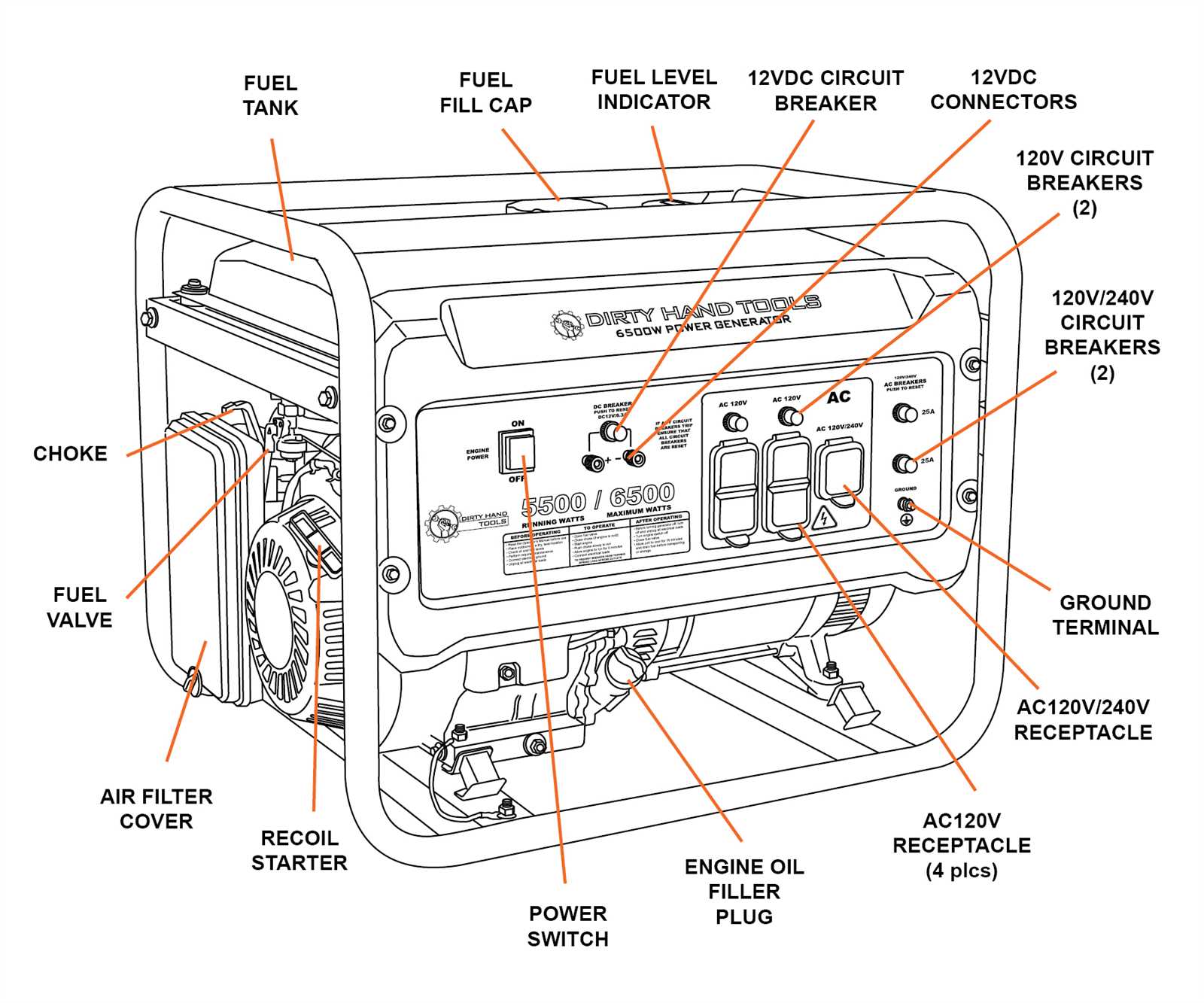
The framework typically consists of a combination of metal and plastic materials designed to withstand various environmental conditions. Essential components include the main chassis, which serves as the base, and support brackets that reinforce the structure. The choice of materials directly impacts the weight, portability, and durability of the unit.
Mounting Hardware Specifications
Mounting hardware includes bolts, screws, and brackets that secure the frame to the operational mechanisms. These components are engineered to resist vibration and stress, ensuring that the entire system remains intact during use. Proper installation of these elements is vital for safety and efficient performance.
Exhaust System Components Explanation
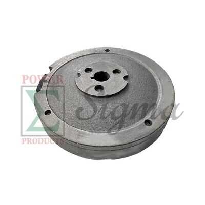
The exhaust system of an engine plays a crucial role in directing harmful gases away from the combustion chamber and ensuring optimal performance. Each element within this system contributes to effective gas expulsion and noise reduction, thereby enhancing the overall functionality of the machine.
Key components of the exhaust system include the exhaust manifold, which collects gases from multiple cylinders and directs them into a single pipe. The exhaust pipe then channels these gases toward the muffler, which is designed to minimize noise produced during operation. Additionally, catalytic converters may be present to reduce harmful emissions, improving environmental compliance.
Further along the system, hangers and brackets provide necessary support, ensuring that the components remain securely attached and properly aligned. The overall design and arrangement of these elements are vital for maintaining efficiency and safety, as any obstruction or damage can lead to decreased performance or potential hazards.