Morbark Chipper Parts Diagram Overview

In diagram

morbark chipper parts diagram

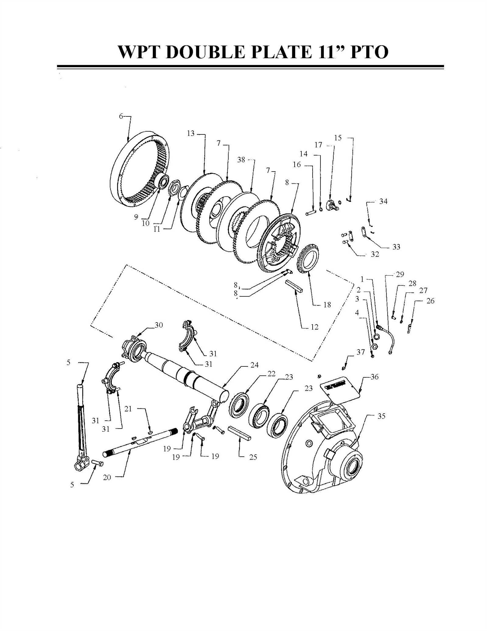
Industrial machines designed for efficient material processing require a comprehensive understanding of their intricate configurations. Each device is composed of numerous interconnected elements, all working together to ensure optimal functionality. Grasping the layout of these elements helps in better maintaining and troubleshooting the equipment, thus ensuring its longevity and efficiency in demanding environments.

The arrangement of various elements in such machinery plays a crucial role in their overall performance. By studying the schematic representation of these elements, one can gain insight into how they interact during operation. Such knowledge proves invaluable for those seeking to maximize efficiency, address potential issues quickly, and ensure smooth operations across various work scenarios.

Delving into the detailed illustrations of these setups not only aids in proper maintenance but also allows operators to familiarize themselves with the key functional areas of their equipment. This understanding becomes especially important when dealing with high-powered machines that are subjected to continuous use in industrial settings, where efficiency and durability are of utmost importance.

Overview of Morbark Chipper Components

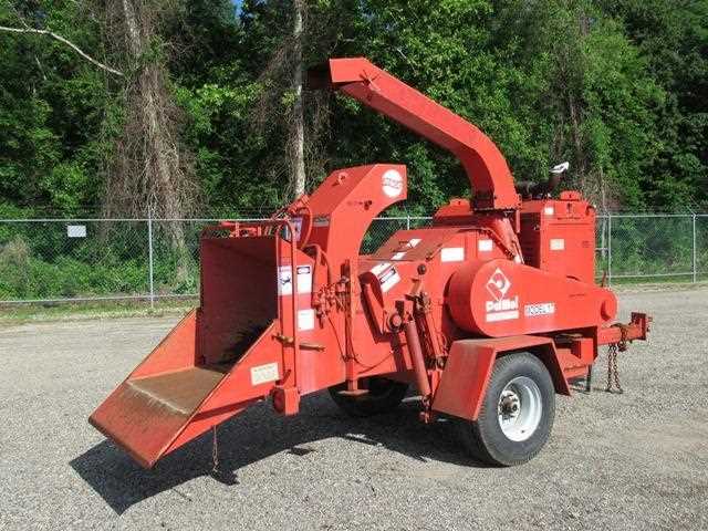
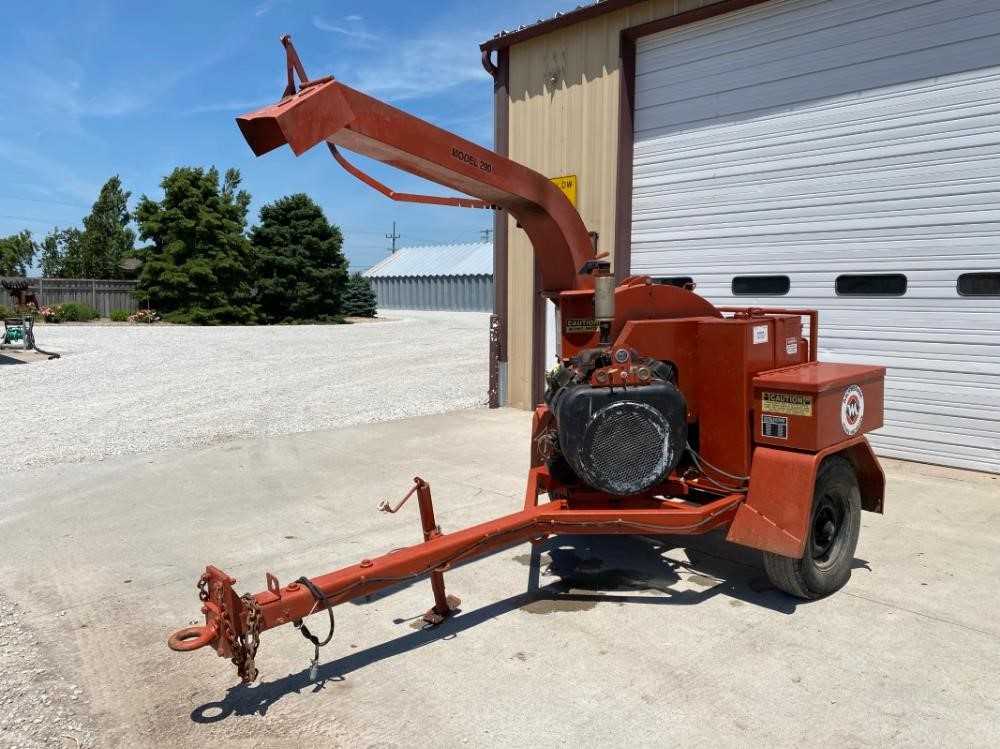
Understanding the structure of this heavy-duty equipment is crucial for maintaining optimal performance. This machinery is designed with several interconnected elements, each playing a specific role to ensure the efficient processing of materials. These elements work together to manage the input and output, allowing for effective breakdown and processing of natural resources.

Key Mechanical Elements
morbark chipper parts diagram

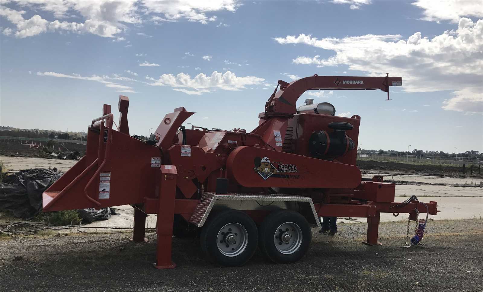
The machine is equipped with a robust engine that powers the entire operation, driving the various mechanical processes. A sophisticated cutting mechanism slices through materials, utilizing rotating blades and a powerful feed system to manage the flow of incoming resources. The discharge system, on the other hand, ensures that processed materials are expelled efficiently, allowing for a smooth operational cycle.

Control and Safety Systems
morbark chipper parts diagram

To ensure safety and ease of use, the equipment includes a range of control features and safety mechanisms. Operators can adjust the speed and intensity of the process through user-friendly control panels, while emergency stop systems provide a quick way to halt the operation if needed. These features not only enhance productivity but also ensure a safer working environment for the user.

Key Features of Morbark Chipper
morbark chipper parts diagram

This equipment stands out in the industry for its robust construction and advanced capabilities, making it a reliable choice for various wood-processing needs. Its design is tailored to enhance productivity, offering both power and efficiency to tackle demanding tasks with ease. Below are some of the most notable characteristics that contribute to its effectiveness.

Characteristic Description
Engine Power Equipped with a high-output engine, it delivers consistent performance, ensuring smooth operation even under heavy loads.
Durable Build The frame and critical components are crafted from high-strength materials, providing long-lasting durability in tough working environments.
Safety Mechanisms Integrated with user-focused safety systems, the unit minimizes risks during operation, offering protection without compromising on functionality.
Adjustable Feed System A versatile feed mechanism allows for customization based on the material type, optimizing the throughput and reducing

Understanding the Cutting Mechanism

morbark chipper parts diagram

The core of any wood-processing machine lies in its ability to efficiently transform raw material into smaller pieces. The intricate system responsible for this transformation is designed to manage a range of materials, ensuring uniformity and speed. It operates through a coordinated sequence of actions, allowing the conversion process to happen smoothly and consistently.

Primary Components of the System

morbark chipper parts diagram

At the heart of the mechanism are the rotating blades, which play a pivotal role in slicing through the material. These blades, made from durable steel, are arranged in a strategic configuration to maximize cutting power. Alongside them, a feed system guides the input towards the rotating elements, ensuring a steady flow and minimizing potential blockages.

Adjustable Elements for Precision

morbark chipper parts diagram

The system often includes adjustable settings that enable operators to modify the size of the output. This flexibility is crucial for adapting to different materials and ensuring the final product meets specific needs. By adjusting the clearance and angle of the blades, the output consistency can be finely tuned, achieving the desired outcome with precision.

Maintenance Tips for Optimal Performance

morbark chipper parts diagram

Keeping your equipment in peak condition requires a consistent approach to upkeep. Routine checks and adjustments ensure that each component functions smoothly, reducing the likelihood of unexpected issues. A proactive maintenance plan can extend the lifespan of the machine and maintain steady output efficiency.

Regular Cleaning and Lubrication

morbark chipper parts diagram

Accumulated debris and dust can interfere with moving mechanisms, leading to wear and tear over time. Periodic cleaning of these areas is crucial to avoid blockages. Additionally, applying the right type of lubricant to rotating parts minimizes friction, promoting smoother operation and reducing strain on the system.

Inspection of Wear-Prone Components

morbark chipper parts diagram

Some parts experience higher stress levels and tend to degrade faster. Regularly inspect these elements for any signs of wear, such as cracks or dull edges. Replacing worn parts promptly can prevent further damage to other sections, ensuring consistent operation and avoiding costly repairs in the long run.

Replacing Worn-out Blades

morbark chipper parts diagram

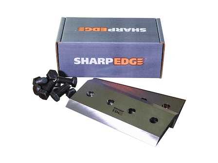
Changing deteriorated cutting edges is a crucial maintenance task to ensure efficient operation and safety. Over time, these components become less effective, which can lead to reduced performance and potential damage to other mechanisms. Regular inspection and timely replacement help maintain peak functionality and prolong the lifespan of the equipment.

Signs of Blade Wear

  • Decreased output efficiency, resulting in slower processing.
  • Visible nicks or cracks along the edges.
  • Uneven cuts that leave behind rough surfaces.
  • Frequent need for sharpening, indicating loss of material strength.

Steps for Safe Replacement

morbark chipper parts diagram

  1. Disconnect the power source and secure the machine to prevent accidental activation.
  2. Use appropriate tools to remove the securing bolts or fasteners.
  3. Carefully lift out the worn elements, avoiding contact with sharp edges.
  4. Clean the mounting

    Hydraulic System Essentials

    morbark chipper parts diagram

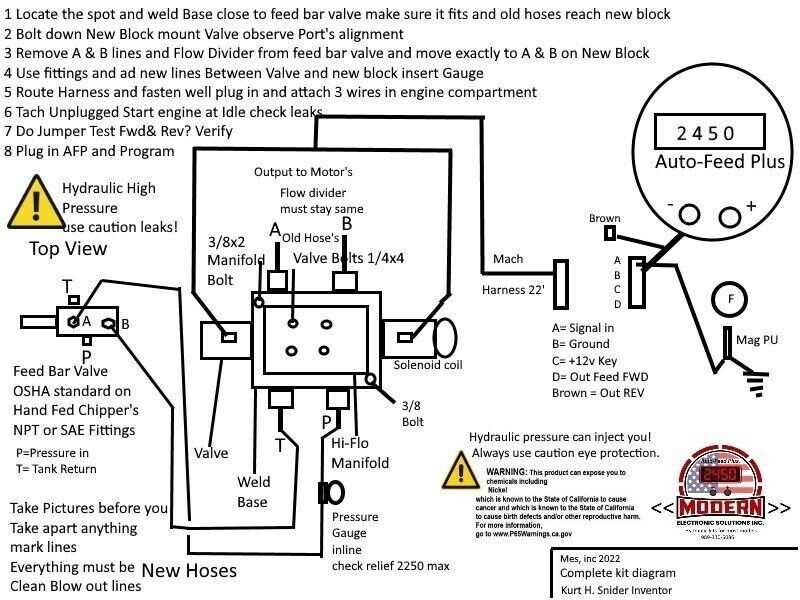
    The core of any hydraulic mechanism relies on the efficient transfer of power through pressurized fluids. This approach allows for seamless operation of various components, ensuring smooth movement and high force transmission. Understanding the critical elements of this system is essential for optimal functionality and maintenance.

    • Pumps: These devices convert mechanical energy into hydraulic energy, generating the pressure needed to drive the fluid through the system.
    • Valves: Controlling the flow and direction of the fluid, valves play a pivotal role in regulating pressure and ensuring precise movement within the system.
    • Cylinders: Cylinders transform the hydraulic pressure into linear force, allowing the conversion of fluid energy into mechanical movement.
    • Filters: These components maintain the cleanliness of the fluid, preventing contamination and ensuring the longevity of the entire mechanism.
    • Hoses and Connectors: Essential for transporting the pressurized liquid, these elements ensure a secure and leak-free pathway throughout the system.
    1. Maintenance Tips: Regularly inspect for leaks, monitor fluid levels

      Electrical Wiring and Control System

      morbark chipper parts diagram

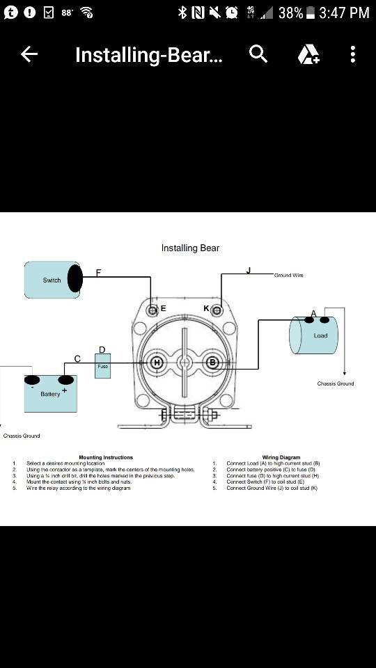
      The functionality of machinery relies heavily on a well-structured network of circuits and control units. This setup ensures seamless coordination between various components, allowing for precise adjustments and efficient operation. The arrangement of conductors, switches, and relays creates a streamlined pathway for electrical currents, making it possible to manage the equipment’s various functions effortlessly.

      Wiring Arrangement: The organization of cables and connectors plays a crucial role in maintaining stability and performance. Properly insulated lines help prevent electrical faults and ensure that power is distributed consistently to different sections of the system. This arrangement also facilitates quick troubleshooting, allowing technicians to identify and resolve issues effectively.

      Control Mechanisms: A series of controllers, sensors, and actuators regulate the operation of the machinery, providing a way to adjust settings and monitor performance. These elements work in tandem, receiving inputs and translating them into specific actions. The control unit serves as the brain, interpreting signals and ensuring that every function is executed with precision.

      Maintenance Considerations: Regular inspections of the wiring and control units are essential for optimal performance. This includes checking for wear in connectors, ensuring secure connections, and verifying the accuracy of control settings. Routine maintenance minimizes the risk of malfunctions and extends the lifespan of the equipment.

      Common Issues and Troubleshooting

      morbark chipper parts diagram

      In any heavy machinery, occasional malfunctions can occur, leading to operational challenges. Understanding these potential problems and their solutions is essential for maintaining efficiency and extending the lifespan of the equipment.

      Frequent Problems

      • Stalling: Equipment may stop unexpectedly, often due to fuel issues or blockages.
      • Noisy Operation: Unusual sounds can indicate loose components or worn parts.
      • Overheating: Excessive heat can result from inadequate lubrication or airflow obstructions.
      • Inconsistent Performance: Fluctuations in power output may stem from electrical faults or debris accumulation.

      Troubleshooting Steps

      morbark chipper parts diagram

      1. Inspect the fuel system for leaks or contamination.
      2. Check for loose bolts or screws and tighten them as necessary.
      3. Ensure that cooling systems are clear and functioning properly.
      4. Examine electrical connections and test for continuity.
      5. Regularly clean and maintain components to prevent buildup and wear.

      By following these guidelines and addressing common issues promptly, operators can enhance reliability and performance, ensuring smooth operation.

      Upgrade Options for Enhanced Efficiency

      morbark chipper parts diagram

      Improving the performance of machinery is essential for maximizing productivity and ensuring optimal functionality. By implementing various enhancements, operators can significantly increase the effectiveness of their equipment, leading to better results in various applications. This section explores several upgrade possibilities aimed at enhancing operational efficiency.

      One of the most impactful modifications involves upgrading the cutting mechanisms. Advanced blades made from high-quality materials can provide sharper edges and greater durability, reducing maintenance frequency and improving performance. Additionally, incorporating enhanced hydraulic systems can boost overall power output, facilitating smoother operation and quicker processing times.

      Another valuable option is integrating advanced control systems. Modern electronics can enhance user interface capabilities, allowing for precise adjustments and better monitoring of operational metrics. Furthermore, adopting alternative energy sources, such as electric or hybrid systems, can reduce emissions and lower operating costs.

      Upgrade Option Description Benefits
      High-Quality Cutting Blades Durable blades that provide sharper edges. Reduced maintenance and improved cutting performance.
      Enhanced Hydraulic Systems Upgraded hydraulic components for increased power. Smoother operation and quicker processing times.
      Advanced Control Systems Modern electronic interfaces for precise adjustments. Better monitoring and operational efficiency.
      Alternative Energy Sources Integration of electric or hybrid systems. Lower emissions and reduced operating costs.

      Investing in these upgrades not only enhances the effectiveness of the equipment but also contributes to a more sustainable and cost-effective operation. Adopting innovative solutions can lead to significant improvements in productivity and overall performance, ensuring a competitive edge in the industry.