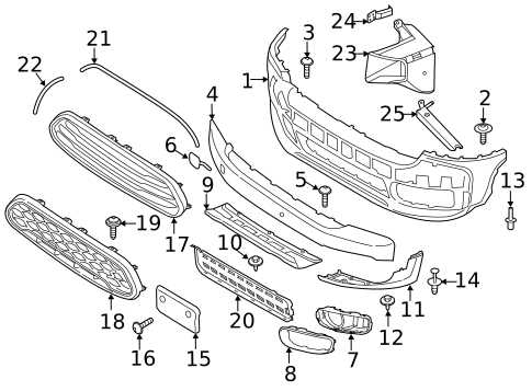
In the realm of design and engineering, the representation of intricate systems plays a crucial role. This approach not only enhances clarity but also aids in communication among various stakeholders involved in the development process.
Visual representations serve as essential tools, allowing for a comprehensive understanding of complex structures. By breaking down the individual elements, one can easily grasp their relationships and functionalities, ultimately leading to improved efficiency.
Furthermore, such illustrations facilitate the identification of potential challenges and opportunities for innovation. As we explore the nuances of these visualizations, we will delve into their significance and applications across different industries.
Understanding Mini Parts Diagrams
Visual representations play a crucial role in comprehending complex assemblies and components within various fields. These simplified illustrations help to convey intricate information in a clear and concise manner, allowing individuals to grasp essential details quickly. By breaking down the overall structure into smaller, manageable segments, these graphics facilitate better understanding and communication.
These visuals serve multiple purposes, such as aiding in troubleshooting, enhancing instructional materials, and providing a quick reference for assembly processes. Their utility extends across industries, from engineering to manufacturing, making them invaluable tools for professionals and enthusiasts alike.
| Key Features | Benefits |
|---|---|
| Clarity | Enhances understanding of complex systems |
| Simplification | Makes intricate processes easier to follow |
| Accessibility | Serves as a quick reference guide |
| Interactivity | Can be used for training and demonstrations |
Components of Mini Parts Diagrams
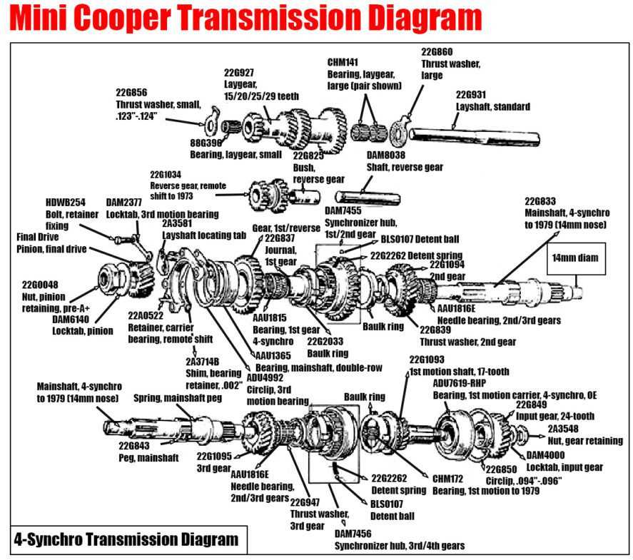
This section explores the essential elements that constitute visual representations in a compact format, designed to convey intricate information effectively. Understanding these components is crucial for creating clear and informative layouts that enhance comprehension and usability.
Key Elements
The primary components that contribute to the functionality of these visual representations include symbols, labels, and lines. Each element serves a specific purpose in facilitating communication and ensuring clarity.
Symbol Overview
| Symbol Type | Description |
|---|---|
| Geometric Shapes | Represent various components and structures within the layout. |
| Arrows | Indicate direction or flow between elements, enhancing understanding. |
| Text Labels | Provide context and identification for each element, ensuring clarity. |
Benefits of Using Mini Parts Diagrams
Utilizing concise visual representations in technical documentation offers numerous advantages for both users and creators. These simplified visuals enhance understanding, allowing for quicker comprehension of complex systems and components. They serve as an effective tool for training, maintenance, and troubleshooting, making intricate details more accessible.
One significant benefit is improved clarity. By breaking down information into digestible sections, these visuals minimize confusion and facilitate faster decision-making. This clarity not only aids in communication among team members but also ensures that essential information is readily available.
Furthermore, such visuals foster efficiency in design and production processes. With a clear overview of elements, teams can identify potential issues early on, leading to cost savings and reduced project timelines. This proactive approach ultimately enhances overall productivity.
Lastly, these representations encourage collaboration. When team members can easily reference and discuss clear visual guides, it promotes a shared understanding and smoother workflow. This collaborative environment is vital for innovation and successful project execution.
Common Applications in Engineering
In the realm of engineering, various components and their configurations play a crucial role in the design and functionality of systems. Understanding how these elements interact and are represented visually aids in efficient problem-solving and innovation across multiple disciplines. This section explores the prevalent uses of such representations in different engineering fields.
Aerospace Engineering
Aerospace engineering heavily relies on visual representations to enhance safety, performance, and efficiency. Diagrams illustrating the arrangement of components are essential for understanding aerodynamics and structural integrity.
Mechanical Engineering
In mechanical engineering, visual aids are fundamental for designing machinery and mechanisms. They help in analyzing the motion, forces, and overall functionality of mechanical systems, facilitating collaboration among engineers and stakeholders.
| Field | Application | Importance |
|---|---|---|
| Aerospace | Aircraft design | Enhances safety and performance |
| Mechanical | Machine design | Facilitates efficiency and collaboration |
| Civil | Infrastructure development | Improves planning and sustainability |
Steps to Create a Mini Parts Diagram
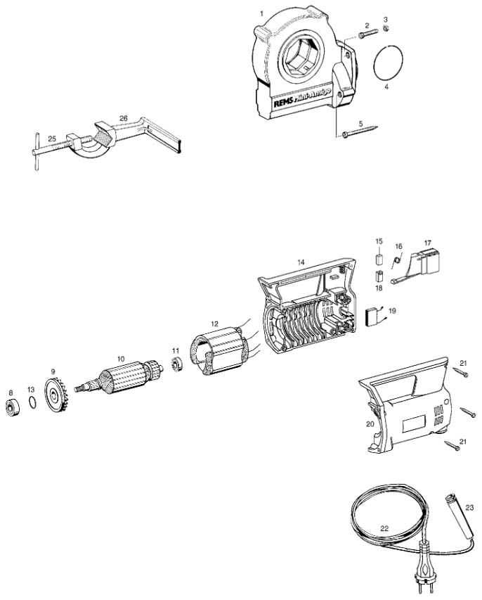
Developing a visual representation of components is essential for clarity and organization. This process involves breaking down complex structures into simpler elements, making it easier to understand how they interact with one another. Here are the steps to effectively create such a representation.
1. Define the Purpose
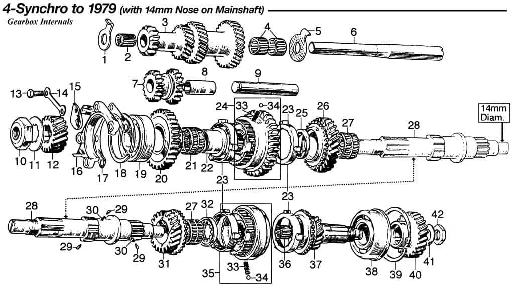
- Determine the main objective of the representation.
- Identify the target audience and their needs.
2. Gather Information
- List all the elements that need to be included.
- Research and collect relevant data about each element.
- Consider how each component relates to the others.
3. Create a Layout
- Choose a suitable format for your representation (e.g., flowchart, schematic).
- Sketch a rough layout to visualize the placement of elements.
4. Use Appropriate Tools
- Select software or tools that facilitate the creation of the visual.
- Familiarize yourself with the features of the chosen tool.
5. Finalize the Design
- Refine the layout based on feedback and personal evaluation.
- Add labels and legends for clarity.
6. Review and Revise
- Check for accuracy and completeness of information.
- Make necessary adjustments for better understanding.
Following these steps will help ensure that your visual representation is not only accurate but also easy to understand, facilitating better communication of ideas and concepts.
Tools for Designing Diagrams
Creating visual representations of concepts and ideas is essential in various fields. The right instruments can greatly enhance the clarity and effectiveness of these illustrations, enabling users to communicate complex information more intuitively. A variety of options are available, each catering to different needs and preferences.
When selecting tools for crafting visual aids, it is important to consider factors such as ease of use, functionality, and the specific requirements of the project at hand. Below is a comparison of some popular applications that facilitate the creation of visual representations.
| Tool Name | Features | Best For |
|---|---|---|
| Lucidchart | Collaboration, templates, integrations | Team projects, online sharing |
| Microsoft Visio | Professional layouts, extensive symbols | Corporate environments, technical uses |
| Draw.io | Free, easy to use, cloud storage | Individuals, small teams |
| Creately | Real-time collaboration, smart shapes | Remote teams, visual brainstorming |
| Cacoo | Interactive features, comment threads | Feedback-driven projects |
Choosing the right tool can significantly impact the quality and impact of your visual communications. Explore the options to find the best fit for your creative needs.
Challenges in Diagram Representation
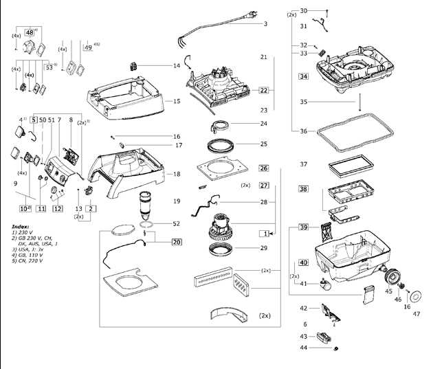
Visual representations of concepts and components can significantly enhance understanding, yet they also pose a variety of obstacles. These challenges can stem from both the creation process and the interpretation by the audience. Effective communication through visuals requires careful consideration of several factors.
- Complexity of Information: When dealing with intricate data, simplifying it without losing essential details can be difficult.
- Interpretation Variability: Different individuals may interpret visuals differently based on their backgrounds and experiences, leading to miscommunication.
- Standardization Issues: A lack of universally accepted symbols or styles can create confusion, especially in cross-disciplinary contexts.
Moreover, the tools used for crafting these visuals can introduce additional hurdles:
- Technical Limitations: Software might not offer the flexibility needed to accurately depict complex relationships.
- User Skill Level: The effectiveness of a visual representation can be hindered by the creator’s proficiency with the tools at hand.
Addressing these challenges requires a strategic approach that balances clarity with comprehensiveness, ensuring that the intended message is conveyed effectively to all stakeholders.
Case Studies and Examples
This section aims to explore practical applications and real-world scenarios that illustrate the concepts discussed. By examining various instances, we can gain insights into effective strategies and innovative solutions that have proven successful in different contexts.
One notable case involved a tech company that streamlined its workflow by implementing a structured visualization approach. This not only enhanced team collaboration but also reduced the time taken to identify and address issues.
Another example features a manufacturing firm that utilized an organized representation of their components to improve inventory management. The result was a significant decrease in waste and an increase in overall efficiency, demonstrating the impact of clarity in operational processes.
These instances highlight the ultimate value of utilizing systematic approaches to achieve goals and foster improvement in various fields.
Future Trends in Diagram Usage
The evolution of visual representations is set to transform how we communicate complex ideas and data. As technology advances, the methods of illustrating relationships and processes will become more sophisticated, enhancing clarity and engagement across various fields.
One significant trend is the integration of interactive elements. Users will increasingly engage with visual tools that allow for real-time manipulation of information, making understanding more intuitive. This interactivity fosters deeper connections and facilitates immediate feedback.
Moreover, the rise of artificial intelligence will lead to smarter systems capable of generating customized visual representations tailored to individual needs. By analyzing user behavior and preferences, these systems can present information in the most effective format, streamlining the communication process.
Another emerging trend is the emphasis on collaborative platforms. As remote work becomes more prevalent, shared visual tools will enhance teamwork, enabling diverse groups to co-create and visualize concepts seamlessly, regardless of geographic location.
Finally, the focus on sustainability will influence the design of visual materials. The push for eco-friendly practices will encourage the development of digital solutions that minimize waste, making visual communication not only effective but also environmentally conscious.