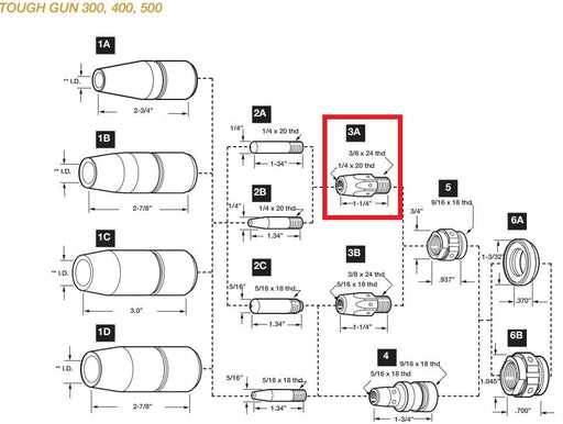
Understanding the structure and internal layout of welding equipment is essential for ensuring smooth operation and efficient repairs. Knowing where each element fits into the overall system can greatly enhance troubleshooting and maintenance processes. This guide focuses on providing an organized view of the core elements in a popular welding machine.
Each internal piece plays a crucial role in maintaining the machine’s functionality. From connectors to power regulators, every element must be properly positioned and well-maintained to guarantee optimal performance. By examining the arrangement of these elements, users can better understand how to address any potential issues that may arise during usage.
With this information, not only will troubleshooting become more straightforward, but performing regular upkeep on the machine will also be more efficient. In this section, we will highlight the critical components and their placement within the system, helping users enhance their understanding of this ess
Component Layout Overview
The structure of this device features various essential elements, each playing a crucial role in ensuring smooth operation. Understanding the arrangement and relationship of these components is vital for proper maintenance and troubleshooting.
Here’s a list of key elements:
- Power supply connection module
- Control panel circuitry
- Cooling system parts
- Wire feed mechanism
- Voltage and amperage regulators
Each part is integrated into the system to ensure efficiency, safety, and performance, making it easier to perform routine maintenance or replace individual sections as needed.
Overview of Millermatic 130xp Components
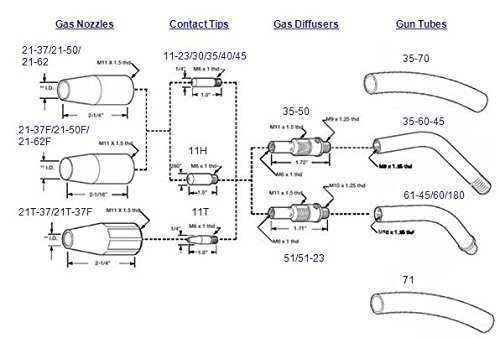
This section provides a detailed explanation of the key elements that make up the functionality of this welding equipment. Each part plays a crucial role in ensuring smooth operation, offering durability and performance. Understanding the main sections and their purposes is essential for efficient usage and maintenance.
Power Supply Unit
The core of the welding machine lies in its power unit, which converts electrical energy into the necessary output for welding tasks. This section is responsible for regulating current and ensuring stable operation during various processes.
Wire Feed System
The wire feeding mechanism ensures consistent and smooth delivery of welding wire. Proper alignment and functioning of this system are critical for achieving clean and precise welds, making it one of the most important components of the overall setup.
Understanding Key Internal Mechanisms
The internal workings of complex welding devices rely on a precise combination of mechanical and electrical components that ensure smooth operation and functionality. Each part plays a crucial role in maintaining stability and delivering consistent performance during usage.
Wire feeding system is one of the essential features, enabling seamless flow of the wire, which ensures precision in the welding process. This mechanism works in tandem with voltage regulation, maintaining the correct energy levels for various welding applications.
Another critical mechanism is the cooling system, which prevents overheating by dissipating excess heat generated during long sessions. This ensures longevity and prevents potential malfunctions in the device.
Wire Feed Assembly and Maintenance Tips
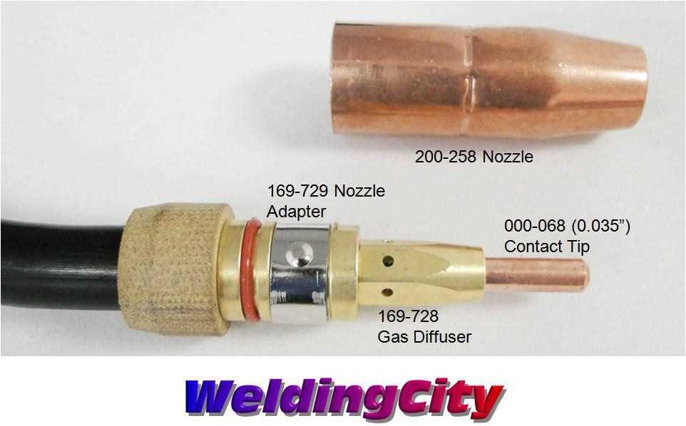
The wire feed mechanism plays a crucial role in ensuring smooth and efficient operation, and regular upkeep is essential to maintain consistent performance. This section covers how to assemble and maintain the wire feed system for optimal functionality, helping to prevent issues that could disrupt work efficiency.
Steps for Assembling the Wire Feed System
- Ensure all components are clean and free of debris before assembly.
- Carefully position the drive rolls in the feed unit, ensuring proper alignment.
- Attach the wire spool securely, ensuring it can rotate without resistance.
- Thread the wire through the guide tubes and into the drive rolls, checking for any kinks or bends.
- Test the tension on the wire to ensure it is not too tight or too loose, as improper tension can cause feeding problems.
Maintenance Tips for Prolonging System Lifespan
- Regular
Safety Features and Their Importance
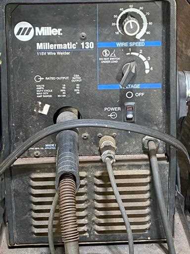
The significance of safety measures in any equipment cannot be overstated. These precautions are essential to ensure that both the operator and the device are protected from potential hazards. Understanding the role of each safeguard allows users to operate machinery with confidence, knowing they are reducing the risks involved.
Protecting the Operator
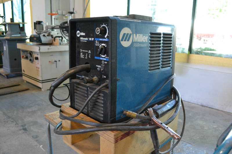
One of the primary functions of safety features is to shield the user from dangerous situations. Whether through physical barriers or automatic shutdown systems, these elements work together to prevent accidents, ensuring a safer working environment. Proper use of these safeguards minimizes the chance of injury and promotes a more secure operational setting.
Extending Equipment Lifespan
In addition to protecting the operator, safety mechanisms also play a key role in maintaining the longevity of the device. By automatically managing overheating, electrical surges, or malfunctions, these systems help to prevent unnecessary wear and tear. Regular maintenance and adherence to safety guidelines ensure the equipment remains in optimal condition over time.
Troubleshooting Common Electrical Issues
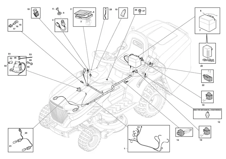
Electrical malfunctions can disrupt the functionality of various devices and equipment. Identifying and resolving these issues is essential to maintain optimal performance and prevent further damage. This section outlines common problems that may arise and offers practical solutions to address them effectively.
Identifying Faulty Components
One of the first steps in troubleshooting electrical issues is to examine the components involved. Look for signs of wear, such as frayed wires or burnt connections. Testing voltage levels with a multimeter can help pinpoint faulty parts. If a component shows inconsistent readings or no power, it may need replacement.
Checking Power Supply
Another critical area to investigate is the power supply. Ensure that the device is plugged in correctly and that the outlet is functioning. Using a voltage tester can verify the presence of electricity at the outlet. If the power source is stable but the device remains non-operational, further inspection of internal circuitry may be necessary.
Proper Care for Welding Gun Parts
Maintaining the functionality of your welding tool is essential for achieving optimal performance and longevity. Proper attention to various components ensures not only efficient operation but also enhances safety during use. This section provides guidelines on how to care for the critical elements of your welding apparatus.
Regular Inspection
Conducting routine checks is vital to identify wear and tear early. Focus on the following:
- Check for any signs of damage or corrosion on the nozzle and contact tip.
- Inspect the cable for fraying or exposure, which can lead to electrical hazards.
- Ensure that all connections are secure to prevent any loss of functionality.
Cleaning Procedures
Regular cleaning is crucial for optimal performance. Follow these steps:
- Disconnect the welding device from the power source before cleaning.
- Use a soft brush or cloth to remove slag and spatter from the nozzle.
- Wipe the contact tip with a suitable cleaner to prevent buildup.
- Periodically replace worn or damaged components to maintain efficiency.
Replacement Guidelines for Worn Components
Maintaining the functionality of your equipment is crucial for optimal performance and longevity. Over time, certain parts may exhibit signs of wear and tear, necessitating their replacement. This section outlines effective strategies for identifying and replacing these components to ensure seamless operation.
1. Regular Inspection: Conduct frequent evaluations of all mechanical elements to detect any deterioration. Look for signs such as unusual noises, decreased efficiency, or visible damage. Early identification of issues can prevent further complications and costly repairs.
2. Use Quality Components: When replacing parts, always opt for high-quality materials that meet or exceed the manufacturer’s specifications. Utilizing inferior components may lead to premature failure and can compromise the overall performance of your equipment.
3. Follow Manufacturer Recommendations: Adhere to the guidelines provided by the equipment manufacturer regarding replacement intervals and procedures. These recommendations are based on extensive testing and are designed to maximize the lifespan of your machinery.
4. Proper Installation: Ensure that all replacements are installed correctly. Improper installation can lead to further damage or malfunction. If necessary, consult a professional technician to guarantee that the components are fitted accurately and securely.
5. Document Replacements: Keep a detailed record of all replacements, including the date, part numbers, and any relevant observations. This documentation will assist in future maintenance and can provide valuable insights into recurring issues.
By following these guidelines, you can effectively manage the upkeep of your equipment, prolonging its operational life and enhancing its overall performance.
How to Read and Use Parts Diagrams
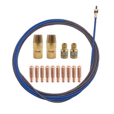
Understanding and utilizing schematic representations of components is crucial for efficient maintenance and repairs. These illustrations provide a visual guide to the various elements of a machine, enabling users to identify each part’s location and function effectively. By familiarizing oneself with these graphical layouts, one can streamline the process of troubleshooting and enhancing equipment performance.
Interpreting the Visual Layout
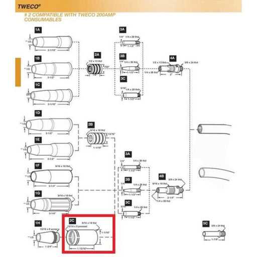
Each schematic typically includes labeled sections that correspond to specific components. Pay attention to the numbering or lettering used, as it often indicates the sequence or relationship between parts. Recognizing common symbols and conventions in these representations will facilitate easier navigation and understanding.
Practical Application in Repairs
When performing maintenance or repairs, refer to the schematic for guidance on disassembly and reassembly. Use the visual cues to locate parts that may need replacement or adjustment. This method not only saves time but also reduces the risk of errors during the repair process, ensuring that the equipment functions optimally.