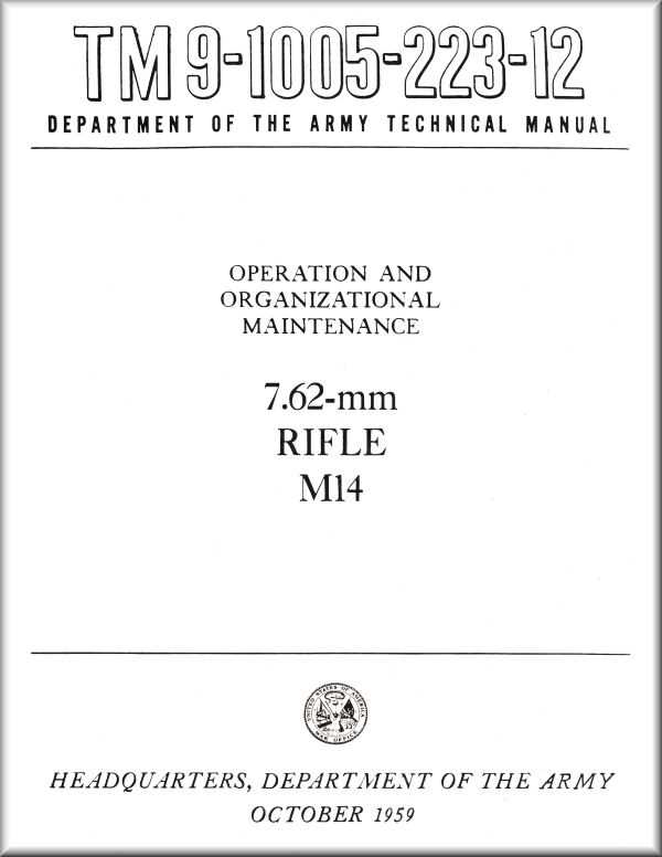
The intricate design of a renowned firearm reveals a fascinating interplay of engineering and craftsmanship. Each element plays a crucial role in the overall functionality, contributing to the reliability and precision that enthusiasts admire. A thorough exploration of these elements can enhance one’s appreciation for this iconic weapon.
In this section, we will delve into the various sections of the mechanism, identifying their significance and how they work together to achieve optimal performance. Whether you are a seasoned expert or a curious novice, understanding these components is essential for anyone interested in the art of firearms.
By examining the layout and functionality of each segment, we aim to provide insights that are not only educational but also engaging. This knowledge can be invaluable for maintenance, modification, and overall familiarity with the rifle’s operation, empowering users to handle their equipment with confidence.
M14 Parts Diagram Overview
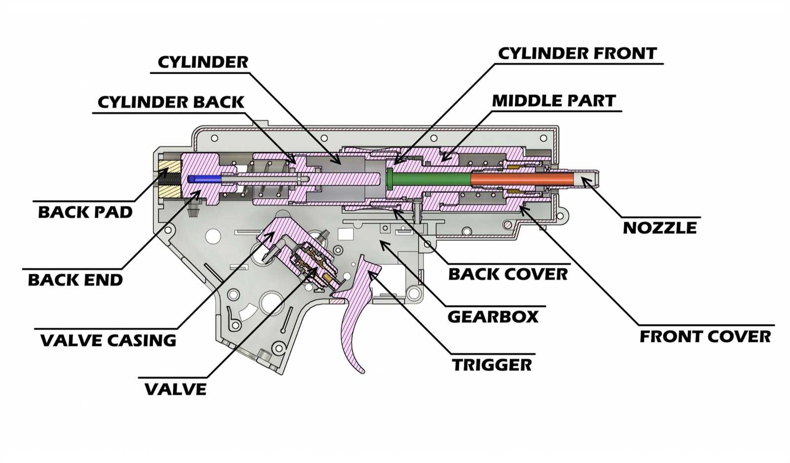
This section provides a comprehensive examination of the components and their interactions within a renowned firearm design. Understanding the various elements and how they fit together is essential for enthusiasts and professionals alike. The assembly plays a crucial role in the functionality and performance of the weapon.
Key elements are often depicted in a systematic layout, allowing for easy identification and reference. Each piece contributes to the overall mechanics, ensuring reliability and accuracy in use. A well-structured illustration aids in grasping the complex nature of the assembly.
In addition, familiarity with these components enhances maintenance practices and troubleshooting techniques. Knowing how each section operates within the larger framework can significantly improve the handling and care of the firearm. This knowledge is invaluable for both novice users and seasoned experts.
Understanding M14 Components Structure

The intricate layout of this classic firearm’s construction requires a closer look to fully appreciate its design and functionality. By breaking down the different elements and examining their arrangement, one can gain a better understanding of how each piece contributes to the overall performance and reliability of the weapon.
Key Structural Elements
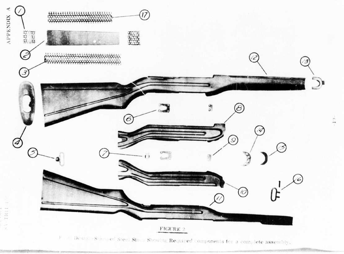
The internal assembly consists of various interconnected pieces that work together seamlessly to ensure smooth operation. Each element is crafted with specific functions in mind, forming a robust system that balances durability and precision. The alignment of these pieces is crucial, allowing for efficient energy transfer and accurate targeting.
Interaction Between Individual Components
The interplay among different segments determines the weapon’s responsiveness and ease of maintenance. When the internal mechanisms engage, each part supports the next, resulting in a consistent and controlled sequence of movements. This synergy enhances the handling experience, making it a reliable choice for various applications.
Key Features of M14 Rifle Parts
When examining the structure of this classic firearm, its components exhibit a balance of durability, precision, and ease of maintenance. Each element is meticulously designed to support reliable operation and performance, contributing to the overall efficiency and user control.
Barrel ensures accuracy and consistency, providing the necessary strength for various firing conditions. Its construction allows for optimal performance under pressure, ensuring stable trajectory and reduced wear.
Trigger mechanism is engineered for responsive action, allowing for precise control with minimal effort. This contributes to both safety and user confidence in handling.
The stock offers comfort and stability, with ergonomic design considerations that enhance grip and overall maneuverability. It’s designed to absorb recoil effectively, making it easier to maintain aim and control during use.
Importance of Accurate Diagrams
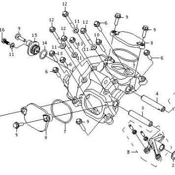
Clear visual representations play a crucial role in understanding and maintaining mechanical systems. When illustrations are precise, they provide a reliable reference for identifying components, understanding their arrangement, and performing repairs or adjustments. The clarity and correctness of these visuals directly impact the efficiency of troubleshooting and maintenance.
Benefits of Precise Visuals
- Enhanced Understanding: Well-drawn visuals help users grasp complex systems quickly, reducing the learning curve for new users.
- Efficient Maintenance: Accurate illustrations ensure that users can identify elements correctly, facilitating timely and effective repairs.
- Error Prevention: By providing exact references, precise visuals help to avoid mistakes during assembly, disassembly, or component replacement.
Impact on Safety and Performance
High-quality visuals contribute to safer operations by reducing the likelihood of misinterpretation. When users have access to exact illustrations, they can follow procedures correctly, minimizing risks associated with incorrect handling. Additionally, this accuracy supports optimal performance by ensuring each component is properly maintained.
Common M14 Parts and Their Functions

The iconic design of this classic firearm includes various components that play crucial roles in its operation. Each element works together seamlessly to ensure reliability, accuracy, and durability. Understanding the purpose of these individual elements helps in maintaining and optimizing the weapon for different scenarios.
The barrel directs the projectile and is responsible for the accuracy and range. Its rifling stabilizes the bullet’s flight, enhancing precision. The stock provides support and stability, allowing for better control during firing. Additionally, the gas system ensures smooth cycling by redirecting energy to reload the next round automatically.
The bolt carrier assembly handles the loading and ejection of cartridges, playing a key role in the firing cycle. The trigger mechanism initiates the firing sequence, offering various settings for user preference. The sights aid in aiming, with options for adjustments to cater to different distances and conditions.
Identifying Parts in a Diagram
Understanding the various elements shown in a schematic illustration can be crucial for anyone looking to maintain or repair a mechanical system. Each component in the visual representation is marked to help users recognize its role and location within the whole structure. Familiarity with these elements allows for accurate troubleshooting and efficient assembly, ensuring that the system operates as intended.
Paying attention to labels and markers in the illustration can help distinguish between similar-looking components. Some items may appear nearly identical but serve different functions, making it essential to identify them correctly. Observing specific features, such as shape, size, and position, will aid in distinguishing these elements.
Learning how to interpret symbols and visual cues is another valuable skill when analyzing these illustrations. Arrows, lines, and annotations often indicate the movement or flow between components, providing additional insights into the function of each part. Becoming proficient in reading these clues can significantly improve one’s ability to understand the system as a whole.
Maintenance Tips for M14 Components
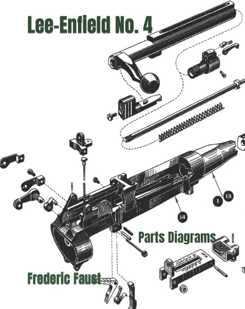
Proper upkeep of individual elements is essential for ensuring reliable operation and extending the service life of the equipment. Regular attention to cleaning, lubrication, and inspection can prevent wear and potential malfunctions, keeping the device functioning smoothly.
Cleaning: Dust, residue, and debris can accumulate over time, affecting the smooth operation. Use a soft brush or cloth to remove buildup, focusing on areas prone to fouling. Avoid harsh chemicals that could damage surfaces.
Lubrication: Apply a suitable lubricant to moving parts to reduce friction and wear. Be cautious not to over-lubricate, as excess oil can attract dirt, causing further issues. Regularly wipe away old lubricant and apply a fresh layer.
Inspection: Routinely check for signs of wear, cracks, or corrosion on critical components. Early detection of issues allows for timely replacement or repair, preventing more serious damage. Tighten any loose connections to ensure optimal performance.
Adopting these practices helps maintain the efficiency and longevity of the equipment, reducing the need for frequent repairs and enhancing overall reliability.
Upgrading M14 Parts Effectively
Enhancing the performance of your equipment involves selecting appropriate components and applying smart modifications. By focusing on targeted improvements, users can achieve better handling, accuracy, and reliability without compromising the system’s balance.
Consider these strategies for effective upgrades:
- Opt for high-quality materials: Premium materials contribute to better durability and efficiency. Investing in well-crafted components ensures smoother operation and longer lifespan.
- Focus on compatibility: Make sure that new additions match the existing setup. This minimizes adjustment time and ensures seamless integration with the current configuration.
- Adjust for precision: Fine-tuning certain elements can significantly improve accuracy and control. Consider upgrading elements related to alignment and stability for enhanced targeting capabilities.
- Upgrade in stages: Implement changes gradually to monitor their impact. This approach allows for easier troubleshooting and adjustments while avoiding overwhelming alterations.
- Maintain proper balance: Keep the system’s overall weight and distribution in mind. Prioritize modifications that enhance performance without adding unnecessary bulk.
With these methods, optimizing your equipment becomes a manageable and rewarding process, yielding noticeable improvements in overall functionality.
Resources for M14 Parts Diagrams
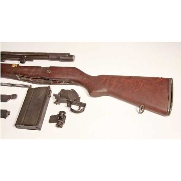
When it comes to exploring blueprints and mechanical layouts, various online platforms and reference materials can provide detailed visuals and technical information. These resources often feature comprehensive illustrations, specifications, and assembly guides, aiding enthusiasts and professionals alike in understanding intricate mechanisms and components.
Online Platforms and Forums
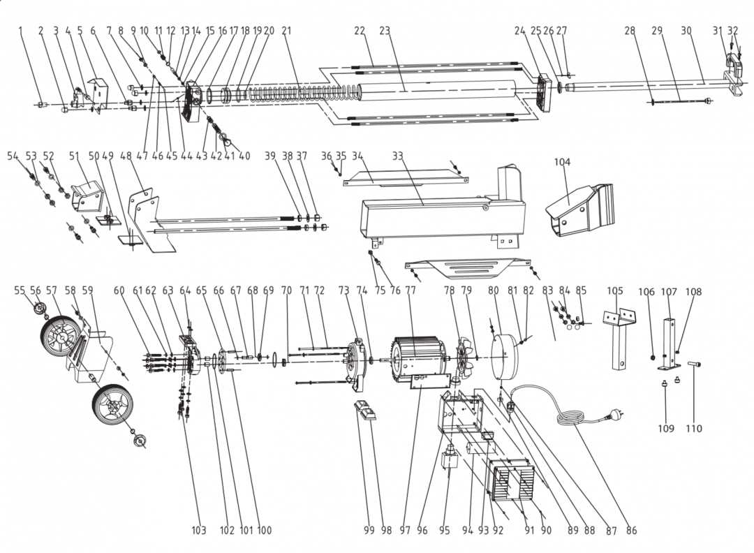
Several websites and community forums host extensive image galleries and technical discussions. These platforms often include high-resolution schematics, allowing users to zoom in on specific sections and identify individual elements. Community members frequently share insights, tips, and alternate versions, contributing to a deeper understanding of various configurations.
Printed Manuals and Books
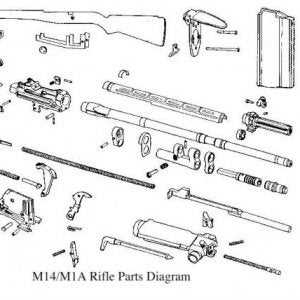
Traditional print resources, such as manuals and specialized literature, offer another way to access detailed visual guides. These books often include exploded views and labeled illustrations, providing a clear picture of individual components and their connections. Libraries and bookstores with a focus on technical publications may have valuable collections for enthusiasts seeking physical copies.
- Online repositories with downloadable guides and visual aids
- Discussion boards with experienced members sharing annotated schematics
- Bookstores specializing in technical and mechanical reference literature
These resources collectively ensure that comprehensive information is accessible to anyone looking to dive deeper into the structural details and assembly processes.