Exploring Kubota B2650 Parts Diagram and Components

In diagram

kubota b2650 parts diagram

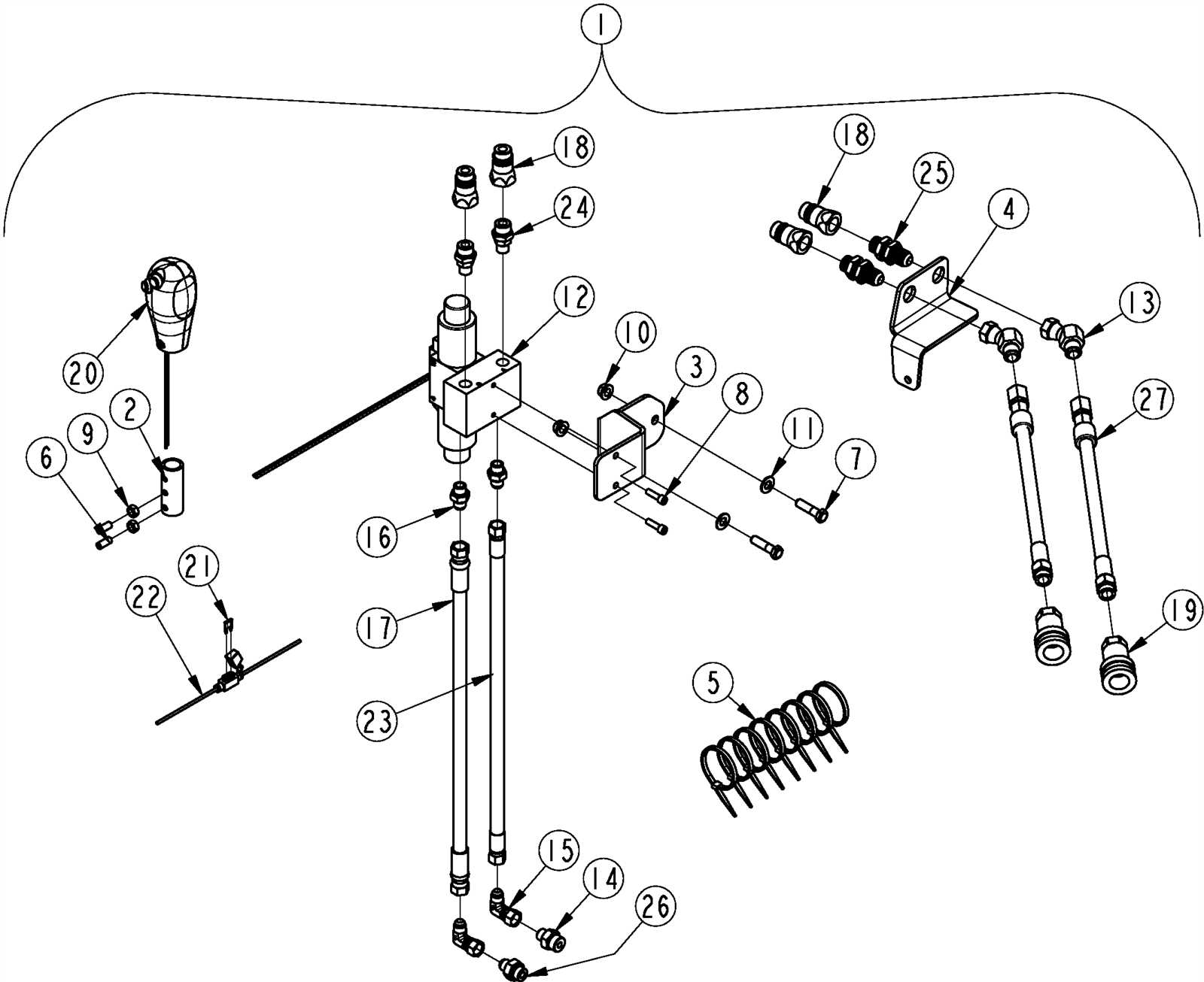
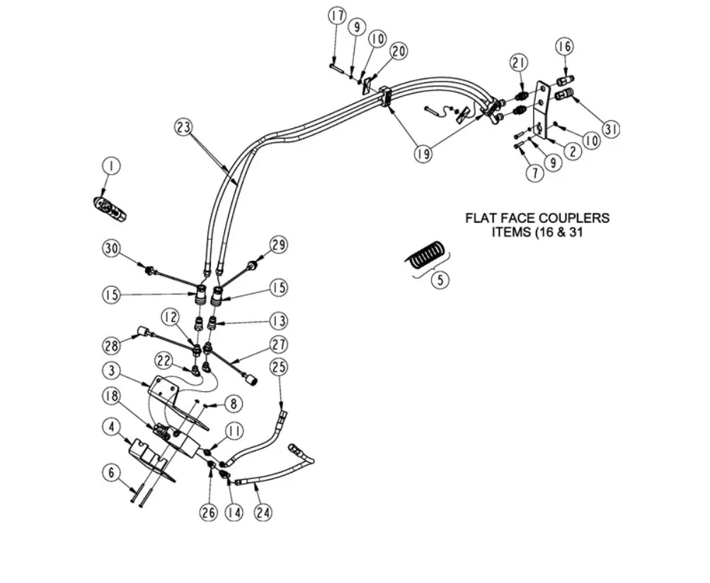
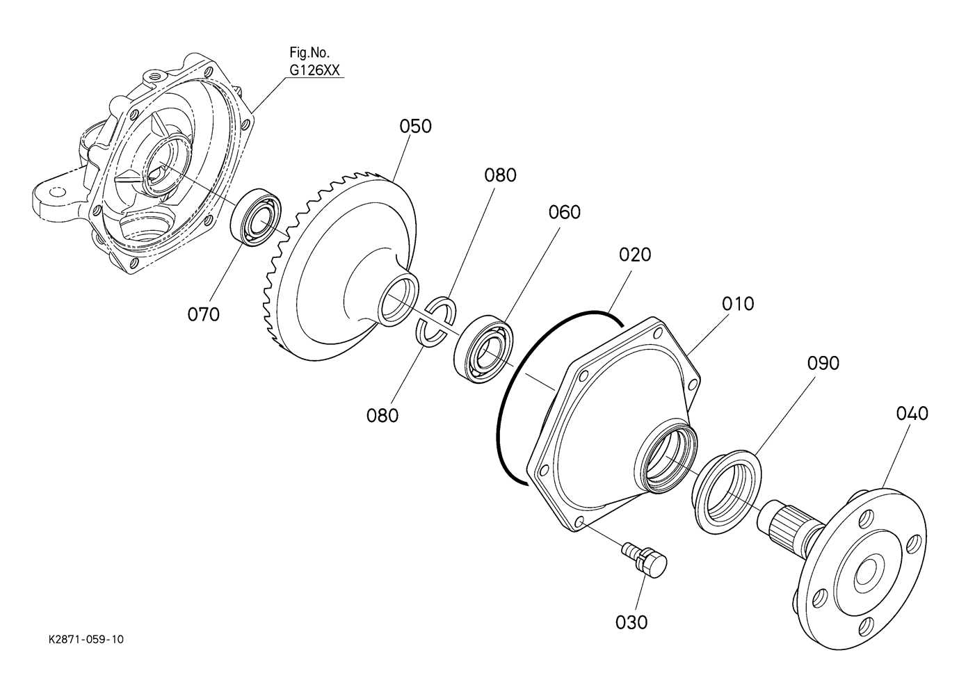
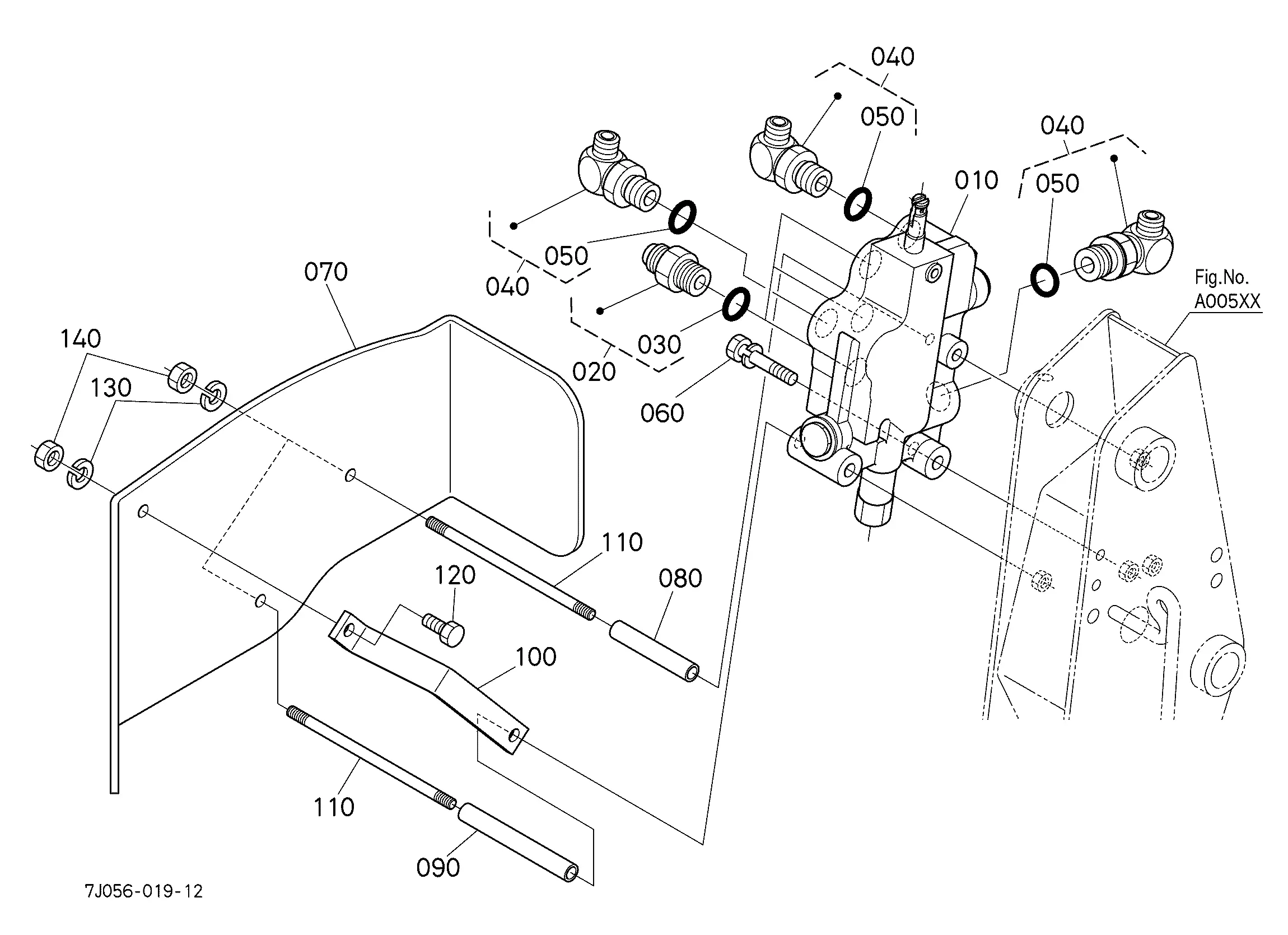
Understanding the structure and arrangement of mechanical systems is essential for ensuring smooth operation and proper maintenance. Each element plays a vital role in the overall functionality, and knowing where these elements are located can streamline repair and servicing tasks.

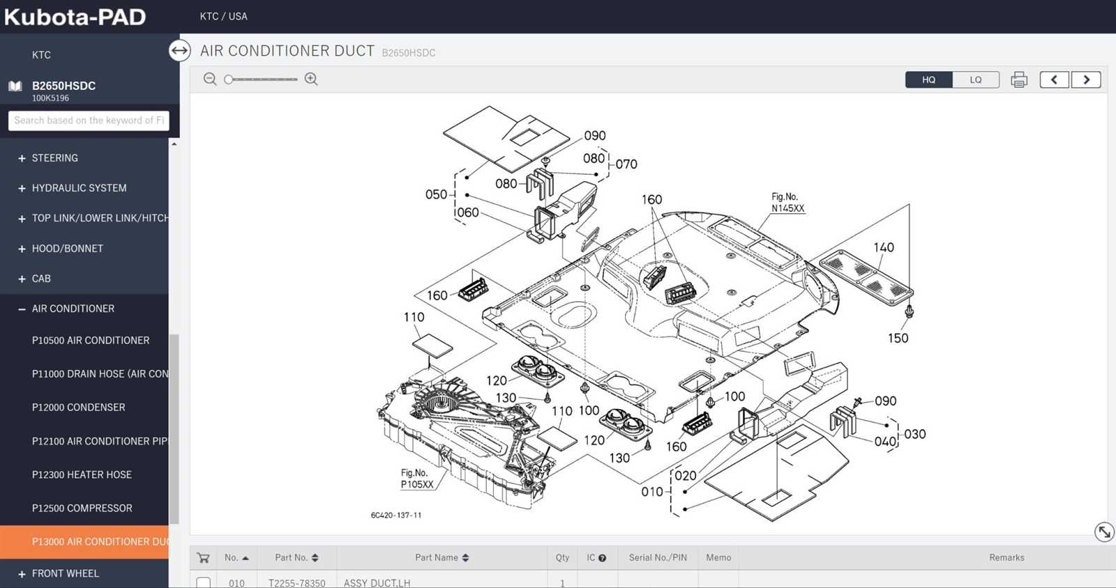
Detailed illustrations provide a visual guide to various mechanical assemblies, making it easier to identify specific components. These visual aids also offer valuable insight into how different parts interact within the system, ensuring accurate reassembly after inspections or replacements.

Whether dealing with routine maintenance or troubleshooting unexpected malfunctions, accurate schematics are indispensable. They serve as a reference point, helping both technicians and operators maintain peak efficiency while minimizing downtime.

Kubota B2650 Parts Diagram Overview

kubota b2650 parts diagram

A clear and organized breakdown of machine components is essential for smooth maintenance and repairs. This section focuses on providing insight into the structure of key assemblies and how different elements interconnect, ensuring reliable performance and extended lifespan of agricultural equipment.

Core Assemblies and Their Functions
kubota b2650 parts diagram

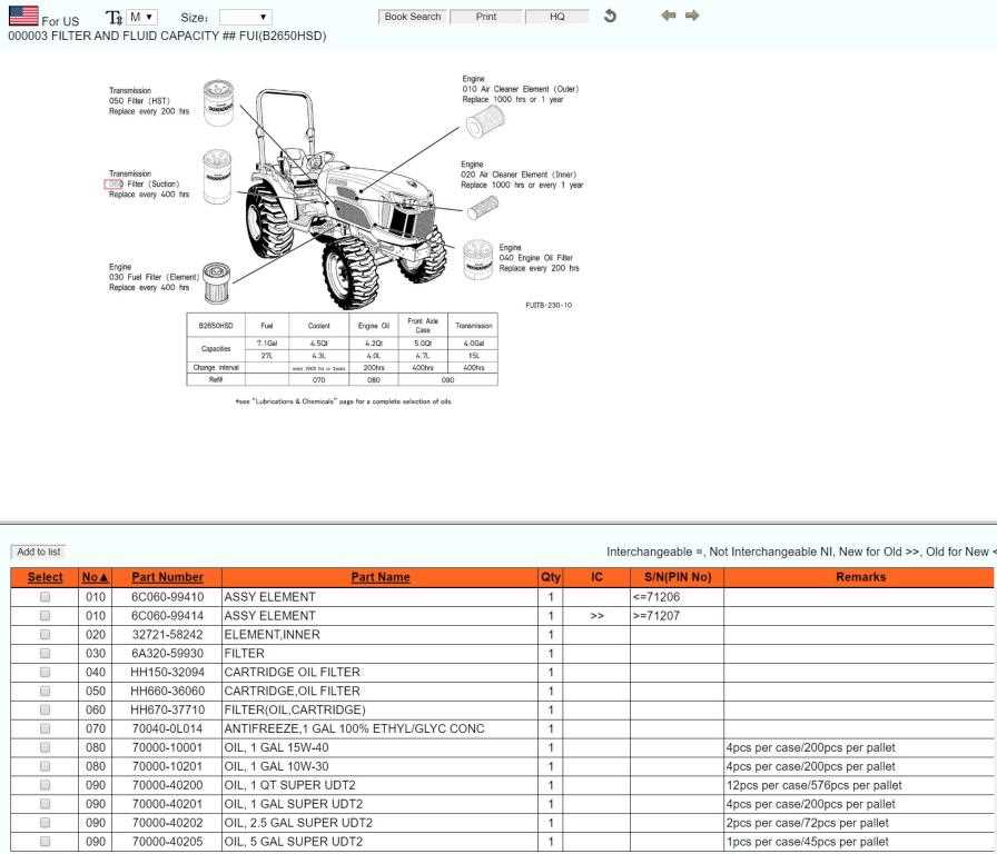
The main assemblies include various mechanical and hydraulic elements, each designed for specific roles. Identifying these elements correctly simplifies troubleshooting and guarantees efficient upkeep. Proper understanding of connections between components, such as the transmission system or the hydraulic pump, contributes to improved efficiency in operation.

Importance of Accurate Component Identification

kubota b2650 parts diagram

Recognizing each element’s role is

Engine Component Layout Explained
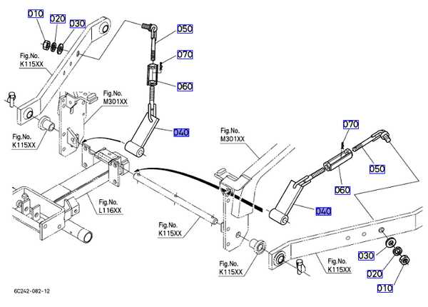
kubota b2650 parts diagram

The arrangement of engine components plays a crucial role in ensuring smooth operation and long-term durability. Understanding how different elements are positioned helps identify potential issues early and improves maintenance efficiency.

At the heart of every engine, key elements like the cylinder block, crankshaft, and piston assemblies form the core. These elements work together to convert fuel into mechanical energy. Additionally, components such as the cooling system, air intake, and exhaust pathways ensure optimal temperature control and air circulation.

The positioning of the fuel delivery system and ignition components ensures precise combustion timing, while lubrication channels keep moving parts running smoothly. Thoughtful placement of filters

Hydraulic System Structure and Design
kubota b2650 parts diagram

The hydraulic system serves as a vital mechanism for transferring power efficiently through fluid dynamics. It ensures smooth operation by distributing force and motion across various components, maintaining control and precision in diverse applications. The system relies on interconnected elements working seamlessly to achieve consistent performance under varying conditions.

Component Function
Pump Generates fluid flow to transmit mechanical energy through the system.

Transmission and Gear Assembly Breakdown

kubota b2650 parts diagram

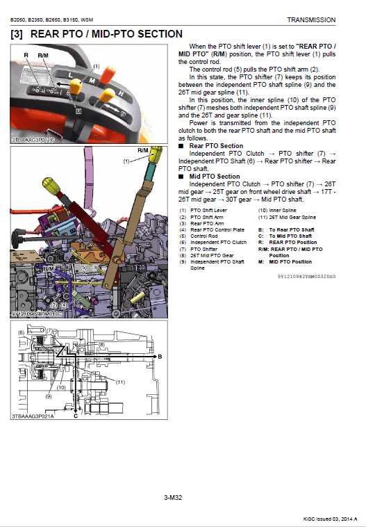
This section provides an overview of the essential components involved in the transmission system and how the gear assembly operates within it. Understanding the intricate structure helps ensure smooth performance and aids in troubleshooting mechanical issues effectively.

  • Main Transmission: Responsible for transferring power from the engine to the drivetrain, ensuring efficient energy distribution across all driving modes.
  • Gear Selector Mechanism: Enables smooth shifting between different speed ranges, offering flexibility in diverse working conditions.
  • Clutch Assembly: Temporarily disconnects the engine from the transmission, allowing safe gear changes wi

    Electrical Wiring and Control Modules

    kubota b2650 parts diagram

    The electrical system and control units ensure seamless operation by managing power flow and coordinating various functions. A well-maintained wiring network enhances performance and safety, minimizing the risk of malfunctions.

    Key Components of the Wiring System

    kubota b2650 parts diagram

    • Wiring Harness: Connects multiple electronic components, ensuring efficient signal and power transmission.
    • Fuse Box: Protects circuits from overload by breaking connections when excessive current flows.
    • Relays: Control high-power devices using low-power signals,

      Chassis and Frame Parts Description

      kubota b2650 parts diagram

      The chassis and frame serve as the backbone of any machinery, providing essential support and structure. Understanding these components is crucial for effective maintenance and repair, ensuring the longevity and performance of the equipment.

      Key elements of the chassis and frame include:

      • Frame Structure: This fundamental framework is designed to bear the weight of various components and distribute stress evenly.
      • Mounting Brackets: These attachments secure different elements to the frame, facilitating stability and proper alignment.
      • Cross Members: Reinforcements that add strength and rigidity to the frame, preventing flexing and deformation.
      • Suspension Components: Parts that connect the frame to the wheels, allowing for smoother rides and better handling over rough terrain.
      • Front and Rear Axles: Critical for mobility, these axles support the weight of the vehicle while enabling movement.
      • Chassis Protection Plates: These shields help guard against damage from debris and rough conditions, extending the lifespan of the underlying structure.

      Regular inspections of these components help identify wear and potential issues, ensuring optimal functionality and safety during operation.

      Cooling System Configuration Guide

      kubota b2650 parts diagram

      This section aims to provide a comprehensive overview of the cooling system setup for your machinery. Understanding the components and their arrangement is crucial for maintaining optimal performance and preventing overheating. A well-designed cooling system ensures that the engine operates within the ideal temperature range, enhancing efficiency and longevity.

      Key Components of the Cooling System

      The primary elements of a cooling system include the radiator, water pump, thermostat, and coolant reservoir. Each of these components plays a vital role in regulating the engine temperature. The radiator dissipates heat, while the water pump circulates coolant throughout the system. The thermostat monitors the temperature, ensuring that the engine reaches its optimal operating conditions.

      Configuration and Maintenance Tips

      kubota b2650 parts diagram

      Proper configuration of the cooling system involves ensuring that all components are securely connected and functioning efficiently. Regular maintenance checks, including inspecting hoses for leaks and replacing the coolant at recommended intervals, are essential for preventing system failures. Regular maintenance helps to identify potential issues before they escalate, ensuring the longevity of your equipment.

      Steering and Axle Component Diagram

      kubota b2650 parts diagram

      This section provides an overview of the essential elements involved in the steering and axle system of a compact tractor. Understanding these components is crucial for maintaining optimal performance and ensuring safe operation.

      Key Components of the Steering System

      kubota b2650 parts diagram

      • Steering Wheel: The primary control interface for navigating the vehicle.
      • Steering Column: Connects the steering wheel to the steering mechanism.
      • Rack and Pinion: Converts the rotational motion of the steering wheel into linear motion for the wheels.
      • Power Steering Pump: Assists in reducing the effort needed to turn the steering wheel.

      Essential Axle Components

      kubota b2650 parts diagram

      1. Front Axle: Supports the front wheels and facilitates steering.
      2. Rear Axle: Transmits power from the engine to the rear wheels.
      3. Wheel Hubs: Houses the bearings and connects the wheels to the axles.
      4. Differential: Allows for variations in wheel speed during turns, enhancing stability.

      Understanding the layout and function of these components is vital for effective troubleshooting and repairs.

      Fuel System Parts Identification

      kubota b2650 parts diagram

      The fuel system is a crucial component in any machinery, responsible for delivering the necessary energy to the engine. Understanding the various elements within this system can enhance maintenance practices and improve overall performance. This section will provide insights into the key components and their functions, enabling users to identify and troubleshoot issues effectively.

      Main Components of the Fuel System

      • Fuel Tank: The reservoir that stores the fuel before it is sent to the engine.
      • Fuel Pump: This device transports fuel from the tank to the engine, ensuring adequate flow and pressure.
      • Fuel Filter: A vital element that removes impurities from the fuel, preventing damage to the engine.
      • Injectors: Components that spray fuel into the combustion chamber, promoting efficient mixing with air.
      • Fuel Lines: Hoses that connect different parts of the system, allowing for the movement of fuel.

      Identifying Fuel System Issues

      kubota b2650 parts diagram

      1. Check for fuel leaks around the tank, lines, and injectors.
      2. Inspect the fuel filter for signs of clogging or contamination.
      3. Listen for unusual noises from the fuel pump, indicating potential malfunction.
      4. Monitor engine performance for signs of hesitation or stalling, which may point to injector issues.

      By familiarizing oneself with the components and potential issues within the fuel system, users can ensure their machinery operates smoothly and efficiently.