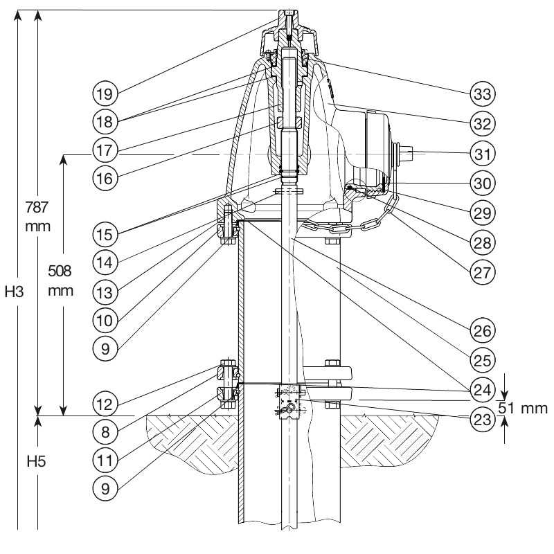
When it comes to maintaining safety and ensuring proper functionality, the detailed organization of various mechanical elements plays a vital role. By exploring the structure and positioning of these elements, one can gain valuable insights into how they function together in harmony to achieve a common purpose. This overview sheds light on the intricate design and helps identify the most critical elements involved in the process.
Each piece within the overall setup has its own function, and their combination ensures efficiency and reliability. Recognizing the layout and specific placement of individual elements is essential for both routine upkeep and repairs. A well-organized structure simplifies troubleshooting and enhances performance.
Detailed schematics can offer a comprehensive understanding of the internal workings, making it easier for technicians and operators to grasp the interconnectedness of all the components. Knowing how these elements fit together can significantly impact the effectiveness of maintenance and operation strategies.
Overview of Hydrant Components
Water distribution systems rely on external fixtures that enable access to the underlying flow. These structures contain multiple internal and external elements, each serving a distinct function. Together, they form a cohesive mechanism designed to control and manage water delivery under various circumstances.
Key Structural Elements
External structures typically include vertical and horizontal connections, enabling access and securing the mechanism to its foundation. These components are crucial for both operational stability and ease of maintenance, providing reliable performance under pressure.
Internal Mechanisms
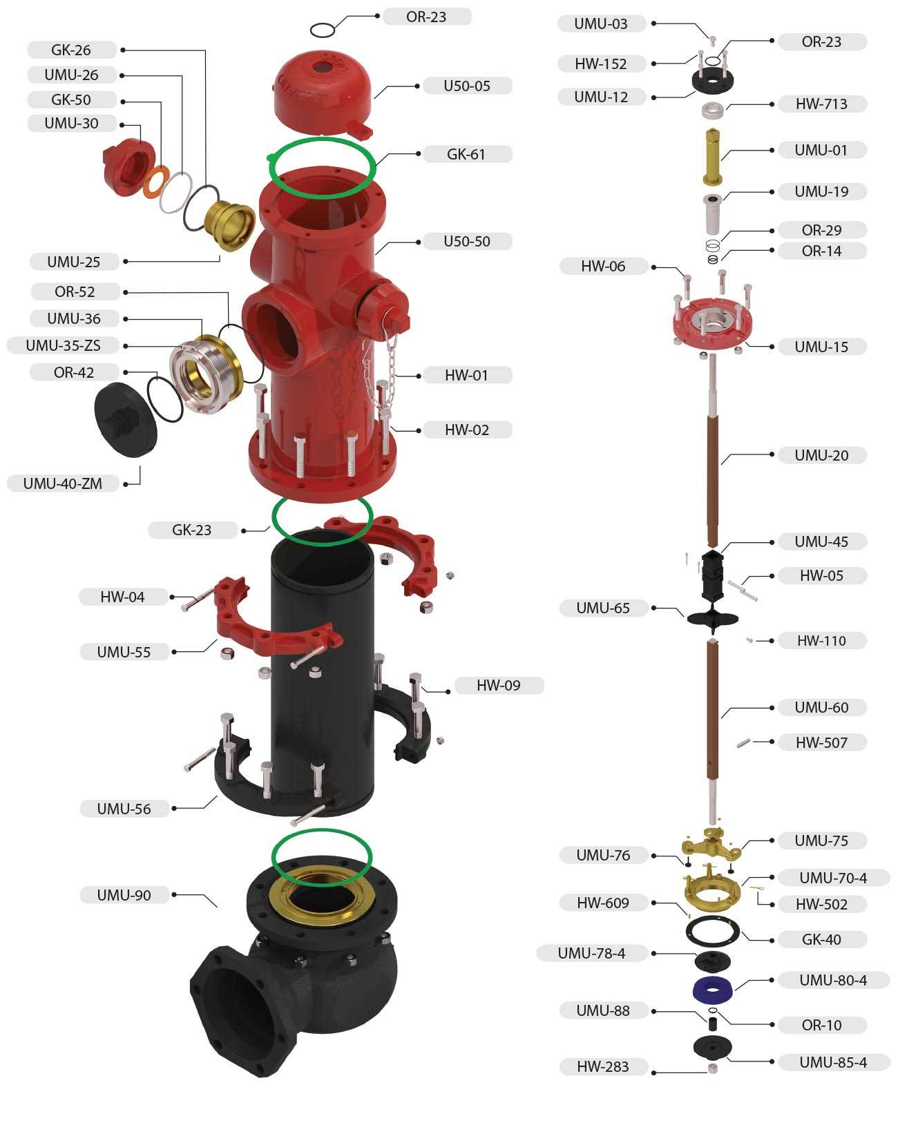
Inside the device, several key elements work in harmony to regulate and control the movement of water. These internal parts are responsible for precise flow regulation, ensuring that water is available when needed and safely contained when not in use.
| Component | Function |
|---|---|
| Valve Assembly | Controls the release and stoppage of water. |
| Sealing Gaskets | Prevents leaks and ensures a secure closure. |
| Risers | Connects the system to the underground supply. |
Main Valve Structure and Function
The primary flow control mechanism is built to regulate liquid movement through a central passage. Its design ensures that liquid is either allowed to pass freely or is stopped completely, depending on the required function. The system operates through a series of interconnected components that work together to control flow with precision.
At the core of this mechanism, there is a key element that opens and closes in response to external pressure. This action is essential for managing the flow within the system, ensuring smooth operation and preventing leaks. The materials used in the construction are chosen for durability and resistance to corrosion, enhancing the long-term reliability of the system.
Each part of the mechanism plays a crucial role in maintaining balance, ensuring proper sealing, and providing resistance to external elements. This ensures that the system remains effective under various operating conditions, making it a reliable solution for controlling liquid flow.
Exploring the Nozzle Configurations
Understanding the variety of nozzle setups is essential for optimizing functionality and efficiency. Each design offers specific advantages, whether for controlling fluid flow or adjusting pressure. The versatility in configurations ensures the right fit for various tasks, enhancing overall performance.
Types of Nozzle Designs

Different designs cater to distinct purposes, ranging from smooth, streamlined options to those engineered for high-impact applications. Some are designed for adjustable flow rates, while others prioritize durability and precision. Choosing the right model depends on the operational requirements and the environment in which it will be used.
Functionality and Use Cases
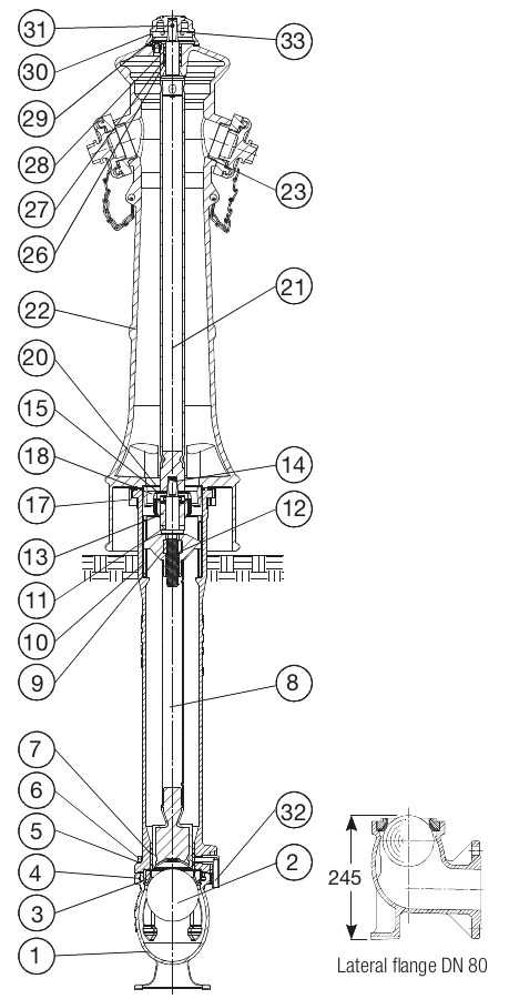
Nozzles are tailored to meet specific operational needs, with some being more suited for wide dispersal, while others focus on delivering a concentrated stream. Each configuration is crafted to address the demands of its environment, ensuring optimal performance under various conditions.
Cap and Chain Mechanism Details
The cap and chain structure plays a crucial role in ensuring protection and accessibility of certain components. This section explores how the cap secures vital areas while the chain ensures it remains attached for quick usage when needed. The design is both functional and durable, preventing loss and minimizing maintenance efforts.
Key Functions of the Cap
The cap serves as a protective barrier, shielding sensitive areas from external elements like dust or debris. It must be easily removable but secure enough to stay in place during various conditions. This balance between security and ease of access is achieved through careful engineering.
Chain’s Role in the Mechanism

The chain’s primary function is to maintain a reliable connection between the cap and the main structure. Made from sturdy materials, it prevents the cap from being misplaced or lost during operation. Its length and flexibility allow for easy removal and reattachment without compromising stability.
| Component | Material | Purpose |
|---|---|---|
| Cap | Metal or Plastic | Protection |
| Chain | Steel | Prevents Loss |
Internal Hydrant Stem Mechanics

The internal mechanics of the stem play a crucial role in regulating the flow within the system. This component, often found deep inside, ensures smooth operation by controlling the upward and downward movement that opens or closes the passageway. Its functionality is essential for the proper management of water or other fluids, offering reliable service even in varying conditions. Understanding its role is key to ensuring long-term performance.
Main Components and Functions
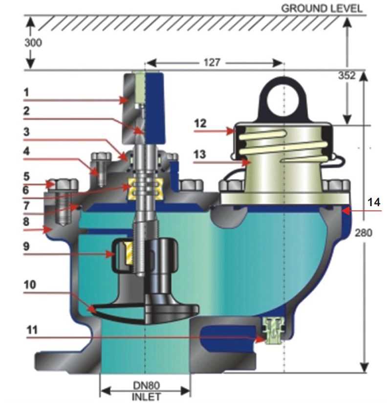
The stem includes several important elements that work together to perform its job effectively. Each part contributes to the overall movement and stability of the structure. Below is a table that breaks down the core elements and their respective functions:
| Component | Function |
|---|---|
| Threaded Rod | Ensures secure vertical movement |
| Seal Mechanism | Prevents leakage during operation |
| Connecting Joints | Links different segments, ensuring stability |
Maintenance Tips for Smooth Operation
Regular checks of the internal components, particularly the moving parts, help maintain efficient functioning. Lubricating the joints and ensuring the seals are intact will prevent wear and tear, enhancing the durability of the entire system.
Understanding the Bonnet Assembly
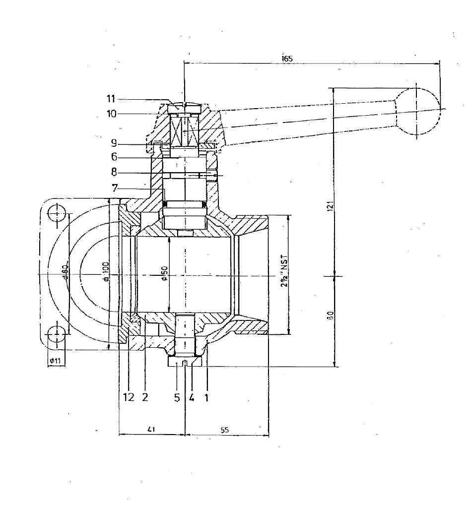
The bonnet assembly plays a crucial role in the functionality of a water distribution mechanism. It serves as a protective cover that houses essential components, ensuring their proper operation while safeguarding them from external elements. This assembly contributes to the overall efficiency and reliability of the system.
Typically constructed from durable materials, the bonnet assembly is designed to withstand high pressures and adverse environmental conditions. Its design incorporates various features that facilitate easy access for maintenance and repairs, thus enhancing the longevity of the entire unit. Understanding the intricacies of this assembly can lead to better management and maintenance practices.
In summary, the bonnet assembly is a vital element that ensures the smooth functioning of the entire water distribution system. Its robust construction and thoughtful design make it indispensable for optimal performance and reliability.
Drain Valve Operation Explained
The functionality of a drain valve is crucial in ensuring effective fluid management within various systems. This component plays a vital role in controlling the release of liquids, facilitating both maintenance and operational efficiency. Understanding its operation is essential for proper application and longevity.
Typically, the mechanism works by allowing fluid to exit from the designated area when needed. Here’s an overview of how this process generally unfolds:
- When activated, the valve opens to permit fluid flow.
- This action can be initiated manually or automatically, depending on the system design.
- As the valve opens, the pressure within the system is equalized, allowing for a safe and controlled release.
- Once the desired amount of fluid has been expelled, the valve can be closed to halt further flow.
Proper maintenance of the drain valve is essential to prevent issues such as leakage or malfunction. Regular inspections and timely servicing can significantly enhance the performance and reliability of this component.
In summary, the drain valve serves as a key element in fluid management, enabling efficient control of liquid release and contributing to overall system functionality.
Breaking Down the Barrel Design
The structure of the vertical component plays a vital role in the overall functionality and efficiency of water distribution systems. Its design is crucial for ensuring that the mechanism operates smoothly under various pressures and environmental conditions.
Key features of this structure include:
- Material Selection: The choice of materials significantly impacts durability and resistance to corrosion.
- Shape and Size: The dimensions are tailored to facilitate optimal flow rates and pressure management.
- Connections: Various fittings and joints must be precisely designed to ensure leak-free performance.
Understanding these elements helps in assessing performance, maintenance needs, and potential improvements in design. Careful consideration of each aspect contributes to a reliable and efficient system.
Maintenance Tips for Hydrant Parts

Regular upkeep of fire safety fixtures is essential for ensuring their reliability and effectiveness. Proper care not only extends their lifespan but also enhances performance, preventing costly repairs and potential hazards. Implementing a routine maintenance schedule is crucial for achieving optimal functionality.
Routine Inspection
Conducting regular checks is vital for identifying potential issues early. Here are key aspects to focus on during inspections:
- Examine seals and gaskets for signs of wear or damage.
- Inspect all connections for leaks or corrosion.
- Ensure all moving components operate smoothly without obstructions.
Cleaning Procedures
Keeping components clean is essential for preventing buildup that can hinder performance. Follow these cleaning steps:
- Use a soft brush or cloth to remove dirt and debris from surfaces.
- Apply appropriate cleaning solutions to eliminate grime, ensuring they are safe for use.
- Rinse thoroughly with water to prevent any residue.