Husqvarna RZ5424 Parts Diagram and Component Overview

In diagram

husqvarna rz5424 parts diagram

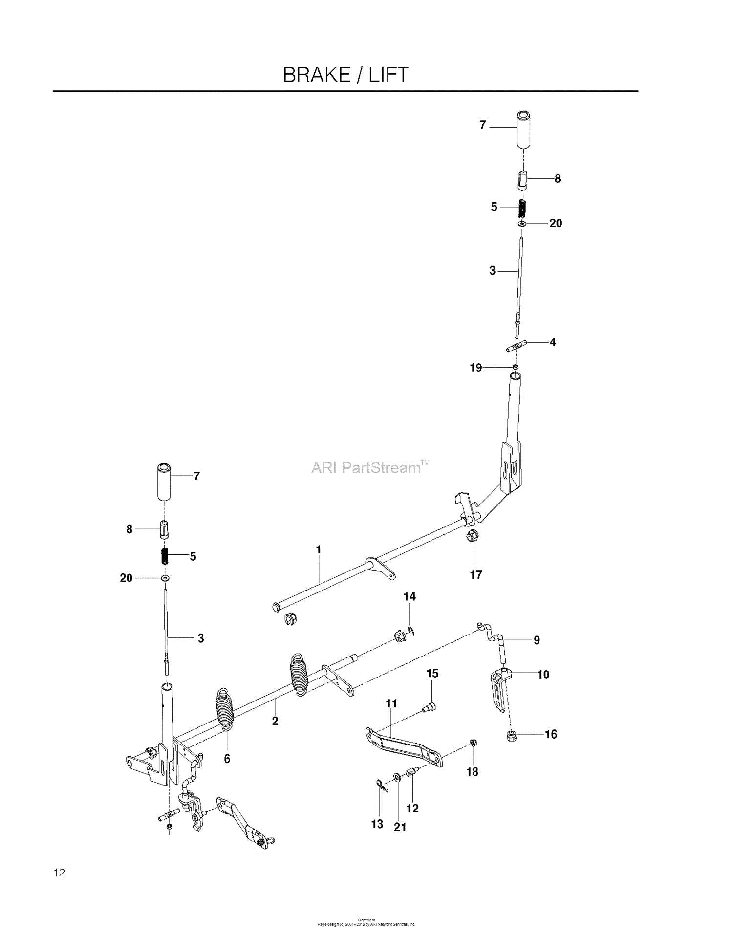
Exploring detailed illustrations of mechanical assemblies provides valuable insight into how each element functions within a system. These visual guides ensure a smooth understanding of structural relationships, offering clarity for both routine maintenance and complex repairs. When every component has its place, troubleshooting becomes more efficient.

Whether you’re maintaining outdoor equipment or troubleshooting an issue, having access to accurate schematics helps streamline the process. They allow technicians to identify necessary replacements with precision, ensuring optimal operation. A clear understanding of these designs minimizes downtime and prevents costly mistakes during disassembly or repair.

Detailed layouts not only support repairs but also assist in proactive upkeep. Regular inspections using these diagrams help spot early signs of wear and tear, reducing the risk of major failures. Familiarizing yourself with these configurations ensures your machinery performs at peak levels, extending its lifespan and enhancing productivity.

Overview of Key Components

This section provides insight into the essential elements ensuring the smooth functionality and performance of the equipment. Understanding these components is crucial for proper maintenance and optimization, allowing users to troubleshoot issues and replace necessary elements effectively.

Engine and Drive System

The power source and transmission system work together to propel the machine efficiently. A well-tuned engine delivers the required force, while the drive system distributes this power to the wheels, ensuring stable movement across various surfaces.

Cutting Deck Assembly

The cutting mechanism is designed to provide consistent results. Key elements include rotating blades, spindles, and belts, all contributing to even grass trimming. Regular inspection of these components ensures smooth operation and prevents performance degradation over time.

Blades and Cutting Deck Mechanism

The efficiency of the mowing system relies on the seamless operation of its sharp edges and deck assembly. This section focuses on how the rotating components interact with the deck structure to ensure smooth trimming performance and consistent grass cutting.

At the core of the deck assembly are multiple rotating cutters that slice through vegetation. These elements are positioned beneath the deck, working together to achieve an even cut. Proper alignment, material quality, and rotation speed play critical roles in achieving desired results. The deck also provides protection, ensuring that both users and nearby objects remain safe during operation.

Component Function Maintenance Tip
Engine Provides mechanical power Check oil levels regularly
Component Function
Cutting Blades Ensure a clean cut by rotating at high speeds beneath the deck assembly.
Spindle Assembly Supports the rotation of blades and connects them to the engine’s drive mechanism.
Deck Shell Encases the blades and prevents debris from being ejected outward.
B

Engine Assembly and Drive System

The heart of any riding machine relies on the proper arrangement of its power unit and propulsion mechanism. This section explores how the motor integrates with the transmission elements to ensure smooth and efficient operation. A well-coordinated system is essential to deliver consistent performance across various terrains, minimizing wear and maximizing longevity.

Core Components of the Power Unit

The motor assembly consists of several interconnected elements, including the combustion chamber, cooling system, and fuel delivery components. Precision alignment between these parts guarantees seamless energy conversion, resulting in optimal output. The configuration also ensures reduced vibration, enhancing operator comfort during extended use.

Transmission and Propulsion Mechanism

The drive system connects the engine to the wheels, utilizing belts, pulleys, or hydrostatic transmissions to transfer power. Accurate synchronization between the transmission and the motor allows for responsive acceleration and precise maneuvering. Regular maintenance of these components is vital to prevent slippage and maintain reliability over time.

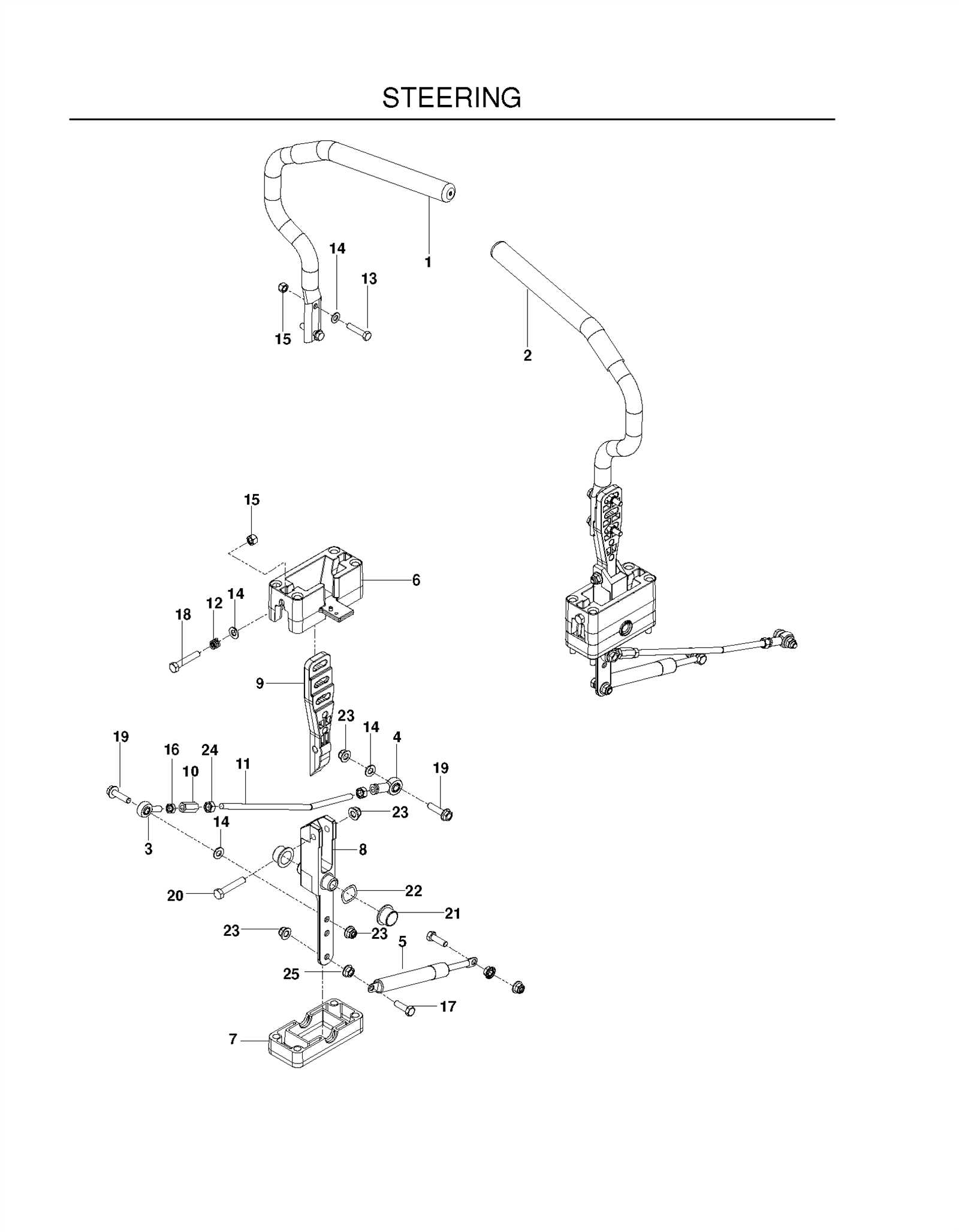
Steering Control and Linkage Setup

The alignment of steering components is essential for smooth operation and responsive handling. This section focuses on the configuration and adjustment of the steering system, ensuring balanced movement and precise navigation. Proper setup minimizes friction and enhances the interaction between various mechanical elements.

  • Initial Inspection: Check for any misalignments or loose connections in the control arms and linkage rods. All bolts and fasteners should be properly secured to avoid unnecessary play.
  • Centering Adjustment: Ensure that the steering mechanism is aligned with the central axis. Adjust the control levers to sit symmetrically when the wheels are in a straight-ahead position.
  • Rod Length Calibration: Adjust the length of the connecting rods to maintain consistent movement between the steering levers and wheels. Equal rod length on both sides prevents uneven turning angles.
  • Tightness Check: Verify that the pivot points and bearings rotate smoothly without resistance. Lubricate joints if necessary to reduce wear over time.
  1. Turn the steering controls to their maximum range in both directions, checking for obstructions or stiffness.
  2. Recalibrate linkage rods if the wheels do not return to the neutral position smoothly after

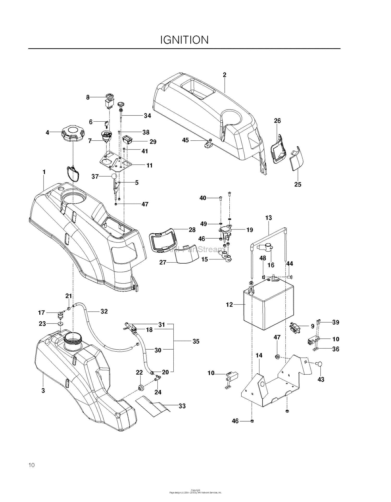
    Fuel System and Maintenance Tips

    The longevity and efficiency of any equipment rely heavily on proper fuel management and routine upkeep. Ensuring smooth operation involves more than just filling the tank; it requires regular inspection, cleaning, and strategic care to prevent common performance issues.

    • Inspect fuel lines periodically for cracks or leaks. Replace any damaged hoses immediately to avoid disruptions.
    • Use fresh, high-quality fuel to prevent buildup and blockages within the system.
    • Check the fuel filter regularly. If clogged or dirty, replace it to maintain optimal flow and engine performance.
    • Drain the fuel tank if the machine will remain unused for an extended period to prevent sediment buildup.

    Beyond fuel-related upkeep, a preventive approach ensures long-term reliability. Minor steps, such as monitoring fluid levels and cleaning essential components, help in avoiding unexpected breakdowns.

    1. Start each session by checking for fuel leaks around connections.
    2. Keep the ai

      Electrical Connections and Safety Features

      Understanding how electrical components are integrated ensures smooth operation and minimizes risks during maintenance. A well-structured network of wiring is essential for proper energy distribution, preventing malfunctions and enhancing system reliability.

      Wiring Integrity and Component Synchronization

      The layout ensures that each connection aligns with the necessary power requirements. Securing wire joints and connectors reduces the chance of loose links, while insulated paths protect against accidental short circuits. Proper synchronization between switches, relays, and sensors ensures seamless functionality under varying load conditions.

      Built-in Safety Mechanisms

      husqvarna rz5424 parts diagram

      Several protective measures are employed to safeguard the electrical setup. Fuses and circuit breakers respond instantly to electrical surges, cutting off power when needed. Grounding points are incorporated to redirect excessive current, ensuring operator safety. These features collectively provide enhanced protection, reducing potential hazards during prolonged use

      Seat Assembly and Comfort Adjustments

      husqvarna rz5424 parts diagram

      Proper setup of the seating area ensures a smooth experience during extended operation, helping to reduce fatigue. A well-positioned seat improves control and allows for more precise handling, enhancing both performance and safety.

      Seat Mounting: Begin by securely fastening the seat to the frame using designated brackets and bolts. Confirm that all fasteners are tightened to prevent unnecessary movement, which could affect stability.

      Adjusting for Comfort: Customize the seat position to match the operator’s height and posture. Use sliding rails or height adjustment levers to align the seat correctly, ensuring an ergonomic sitting posture.

      Lever Positioning and Back Support: Check the placement of adjustment levers for easy access during operation. Ensure the backrest provides adequate lumbar support to minimize strain, especially during prolonged use.

      Regular inspection of the seat mechanism ensures long-term reliability. Lubricate moving components as needed

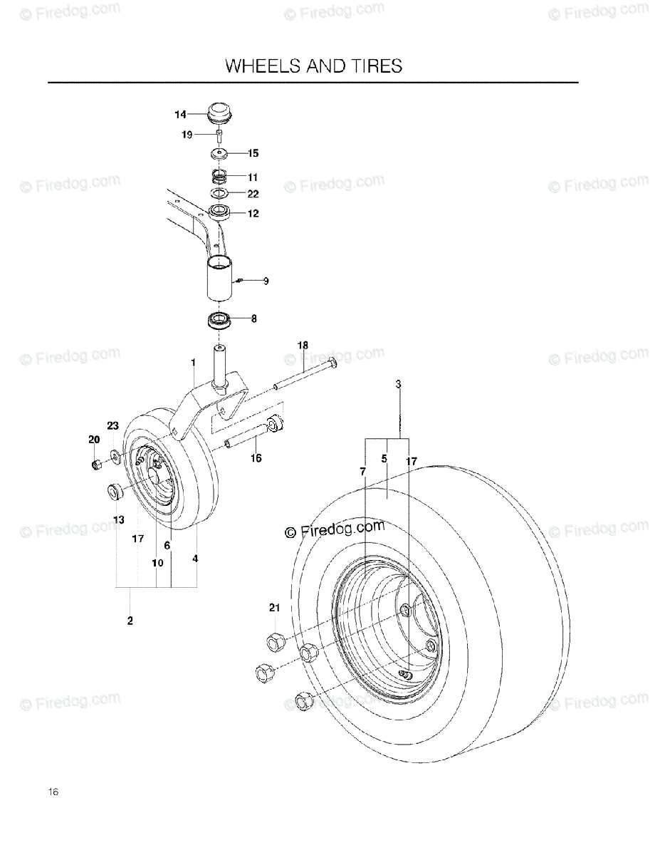
      Tires, Wheels, and Traction Enhancements

      The performance and efficiency of outdoor machinery greatly depend on the components that provide mobility and grip. Selecting the right tires and wheels can significantly influence traction, stability, and overall functionality, especially in challenging terrains. By understanding the various options available, users can enhance their equipment’s performance and achieve better results.

      Tire Types

      • All-Terrain Tires: Designed for versatile use, these tires offer a balanced performance across various surfaces.
      • Rugged Tread Patterns: These tires feature deep treads that improve grip on loose or uneven ground.
      • Flat-Free Tires: Ideal for preventing downtime due to flats, these are filled with solid materials, ensuring continuous operation.

      Wheels and Rims

      husqvarna rz5424 parts diagram

      • Material Options: Steel and aluminum are common materials, each offering different benefits in terms of durability and weight.
      • Size Considerations: Choosing the right wheel size affects maneuverability and stability. Larger wheels can navigate rough terrain more effectively.
      • Design Features: Some wheels come with added features such as reinforcement to enhance strength and performance.

      Implementing traction enhancements can also boost performance. These enhancements may include weight distribution adjustments or the use of specific additives to improve grip. By focusing on the right combination of tires, wheels, and traction improvements, users can optimize their machinery for various outdoor tasks.

      Replacement Tips for Wear Parts

      husqvarna rz5424 parts diagram

      Maintaining optimal performance in equipment involves timely replacement of components that experience regular wear and tear. Ensuring that these items are replaced correctly can prolong the lifespan of the machinery and enhance its overall efficiency. Below are several strategies to consider when addressing the replacement of such components.

      Identifying Wear Indicators

      Before proceeding with any replacements, it is crucial to recognize the signs of wear. Common indicators include:

      • Decreased performance or efficiency
      • Unusual noises during operation
      • Visible damage or degradation on surfaces
      • Excessive vibration or instability

      Replacement Procedure

      When it comes to replacing worn components, following a structured approach can make the process smoother:

      1. Gather all necessary tools and new components.
      2. Consult the manufacturer’s recommendations for specific guidance.
      3. Carefully remove the worn part, noting its orientation and connection points.
      4. Install the new component, ensuring a secure fit and proper alignment.
      5. Test the equipment to verify that the replacement has resolved any previous issues.