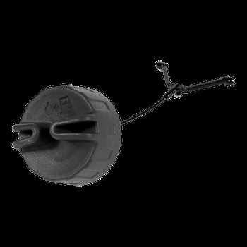
Understanding the structure and organization of various mechanical elements is essential for anyone involved in maintenance or repair tasks. Whether you are a professional technician or an enthusiastic hobbyist, having a clear view of how each element connects and functions is crucial for smooth operation and upkeep. This section will offer insights into the arrangement and relationships of different elements within the system, ensuring a thorough comprehension for effective handling.
For those seeking to maintain peak performance, recognizing the individual components and their roles within the assembly is key. This guide covers the essential elements, explaining their function and positioning, helping users to identify and replace any malfunctioning segments. Detailed descriptions and visual references will enhance your understanding, making the maintenance process efficient and straightforward.
With the right knowledge and resources, anyone can master the intricacies of system maintenance. This guide aims to provide that essential information, ensuring that every user feels confident in their ability to manage and care for their equipment effectively. Dive into the following sections to explore the detailed arrangement and functionality of each part, gaining the expertise needed for successful maintenance and repair.
Comprehensive Overview of Husqvarna 128LD Components
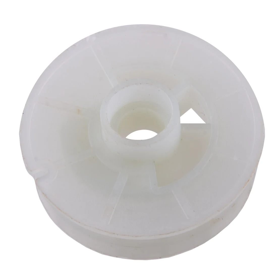
In this section, we provide an in-depth look into the various elements that make up the functionality and efficiency of this versatile tool. Understanding the essential components and their roles will help you maintain and optimize the performance of the equipment for various tasks.
Engine and Fuel System
The power unit is designed for durability and efficiency, featuring a compact engine that delivers consistent power output. The fuel system includes a carburetor and fuel filter that ensure the mixture is accurately regulated, providing the right balance for optimal performance. Regular inspection of these components helps keep the machine running smoothly.
Cutting Mechanism and Attachments
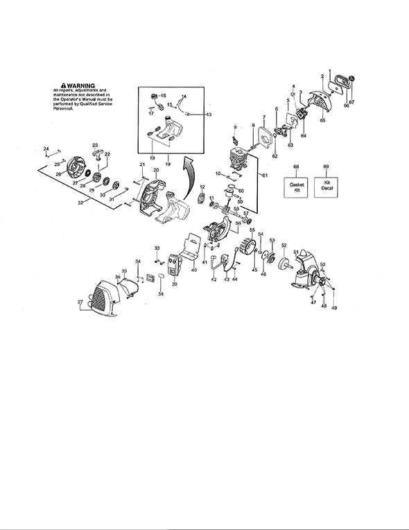
The cutting system incorporates a durable blade assembly and a line head suitable for different vegetation types. Additional attachments can be connected for a variety of tasks, making the equipment versatile for different gardening or landscaping needs. Proper maintenance of these parts, such as regularly checking the blade sharpness and replacing worn-out lines, ensures efficient
Engine Assembly Breakdown and Maintenance Tips
The engine system is a complex structure that requires proper attention and understanding for efficient operation. This section provides an overview of the key components and offers guidance on maintaining the engine for peak performance. Whether you are performing regular upkeep or troubleshooting issues, understanding the fundamentals of engine maintenance will enhance reliability and longevity.
Key Engine Components Overview
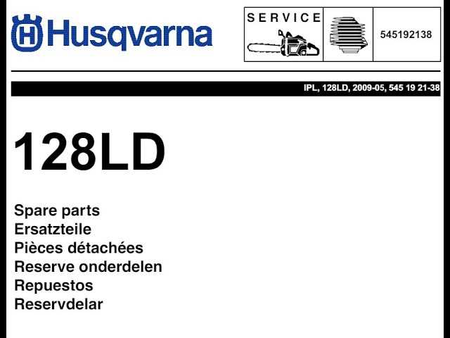
At the core of the engine system are several crucial elements, including the cylinder, carburetor, and crankshaft. These parts work together to ensure the smooth functioning of the machine. The cylinder plays a vital role in combustion, while the carburetor controls the air-fuel mixture necessary for ignition. Regular inspection and cleaning of these components are essential to prevent buildup and ensure optimal performance.
Maintenance Tips for Longevity
To keep the engine in good condition, routine maintenance is crucial. Begin by checking for any signs of wear or damage, particularly on the cylinder and crankshaft. Replace damaged gaskets promptly to prevent air leaks. Additionally, make sure to adjust the carburetor settings as needed to maintain the correct air-to-fuel ratio. Cleaning the air filter and replacing it periodically also helps in maintaining engine
Trimmer Head Components and Installation Guide
This section provides an overview of the essential elements and assembly instructions for the trimming device’s head. Understanding these components and their installation process ensures efficient operation and optimal performance.
The trimmer head consists of several key parts, each contributing to its functionality. Below is a breakdown of these components and a step-by-step guide to correctly attach the head.
- Cover Plate – The protective shield that secures the spool and line inside the head.
- Spool – Holds the cutting line, allowing it to unwind during operation.
- Spring Mechanism – Ensures tension for the automatic feeding of the line.
- Cutting Line – The replaceable filament used for trimming vegetation.
- Mounting Bolt – Fixes the head securely onto the shaft of the tool.
Follow these instructions to install the trimmer head correctly:
- Ensure the tool is powered off and placed on a stable surface.
- Remove the existing head if applicable by unscrewing the mounting bolt.
- Align the new head and secure it by tightening the bolt using an appropriate wrench.
- Insert the spool into the head, ensuring the cutting line is properly wound and positioned through the exit holes.
- Attach the cover plate, locking it firmly in place to secure the spool and line.
- Check the head for stability and manually pull the line to verify the feeding mechanism works correctly.
Properly
Understanding the Fuel System Configuration
The fuel system plays a crucial role in ensuring the proper operation of small engines. It is designed to efficiently deliver the right amount of fuel to the engine, ensuring smooth performance. Understanding how this system is configured helps in maintaining and troubleshooting engine issues related to fuel delivery.
Key Components of the Fuel System
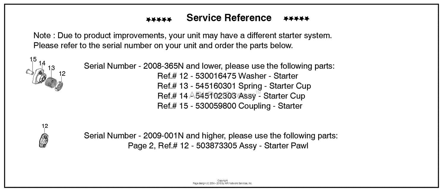
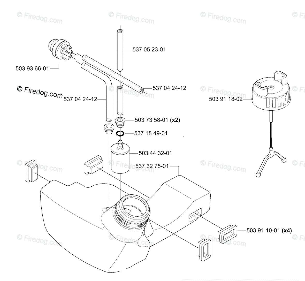
The configuration typically consists of several essential parts that work together to ensure fuel is properly stored, filtered, and supplied to the engine.
- Fuel Tank: Holds the fuel and provides a steady supply to the system.
- Fuel Line: Connects the tank to other components, allowing fuel to flow through the system.
- Primer Bulb: Helps prime the fuel system by pushing fuel into the carburetor before starting the engine.
- Fuel Filter: Removes impurities from the fuel, preventing blockages in the system.
Fuel Flow and Regulation
The system regulates fuel flow to maintain engine efficiency. After fuel passes through the filter, it reaches the carburetor, where air and fuel are mixed. This mixture is then sent into the engine for combustion.
- Fuel is drawn from the tank and passes through the filter.
- The primer bulb helps to push fuel through the system.
- The carburetor adjusts the air-fuel mixture to optimize performance.
Air Filter and Housing Replacement Process
Maintaining the filtration system of your equipment is essential for optimal performance. This section explains the necessary steps to replace the air filter and its surrounding components, ensuring the engine runs smoothly and efficiently.
Step 1: Before beginning, make sure the engine is turned off and completely cooled down. Disconnect any power sources to prevent accidental startups.
Step 2: Locate the cover protecting the filter. Remove the screws or fasteners holding the cover in place, and set them aside for reassembly later.
Step 3: Carefully take out the old filter. Inspect it for dirt and debris, which can indicate how frequently replacements might be needed. Dispose of the used filter appropriately.
Step 4: Examine the housing for any buildup of dust or particles. Use a clean cloth or brush to wipe the area, ensuring it’s free from any blockages that could affect performance.
Step 5: Insert the new filter into the housing, making sure it fits securely. Align it properly to match the shape and orientation of the compartment.
Step
Clutch System and Its Key Parts
The clutch mechanism is a vital component in many power tools, allowing for the smooth engagement and disengagement of the engine’s power to the cutting device. This system plays a crucial role in controlling the tool’s operation and ensuring efficiency during use. Understanding the essential components of the clutch system can help users maintain and troubleshoot their equipment effectively.
Components of the Clutch Mechanism

Several critical elements make up the clutch mechanism, each contributing to its overall functionality:
- Clutch Drum: This part houses the clutch shoes and is responsible for transferring power from the engine to the cutting attachment.
- Clutch Shoes: These components expand when the engine reaches a certain speed, engaging the drum and connecting the power to the cutting tool.
- Spring: The spring mechanism helps to disengage the clutch shoes when the engine speed decreases, allowing for a safe and efficient operation.
Maintenance and Troubleshooting
Regular maintenance of the clutch system is essential for optimal performance. Users should frequently inspect the clutch drum and shoes for wear and tear. Replacing worn parts promptly can prevent further damage and ensure the longevity of the equipment.
Ignition Module Functionality and Repair Methods
The ignition module is a critical component in small engine systems, responsible for initiating the combustion process. It generates the necessary electrical spark to ignite the air-fuel mixture within the engine’s cylinder. Understanding its functionality and potential issues can help in troubleshooting and maintaining optimal engine performance.
Functionality of the Ignition Module
This module operates by receiving signals from various engine sensors, determining the optimal timing for the spark. It ensures that the ignition occurs at the right moment, maximizing efficiency and power output. A malfunctioning ignition module can lead to poor engine performance, increased emissions, and difficulty starting.
Repair Methods for Ignition Module Issues
Repairing issues with the ignition module often begins with thorough diagnostics. Testing the module with a multimeter can help identify any electrical faults. In some cases, cleaning the connections and ensuring proper wiring can resolve minor problems. If significant faults are detected, replacement of the module may be necessary. It is essential to consult the manufacturer’s specifications to ensure compatibility with the engine model during replacement.
Handle and Throttle Control Assembly Details
The handle and throttle control assembly is a crucial component in ensuring optimal performance and maneuverability of outdoor power equipment. This assembly facilitates the user’s ability to operate the machine effectively, allowing for precise control over speed and direction. Understanding its components and functionality is essential for maintenance and troubleshooting.
Components Overview
This assembly typically consists of several key parts, including the grip handle, throttle trigger, and associated linkage mechanisms. The grip handle provides a comfortable hold for the operator, while the throttle trigger enables the user to adjust the engine speed easily. Proper interaction between these components is vital for achieving smooth operation and responsiveness.
Maintenance Considerations
Carburetor Parts and Adjustment Guide
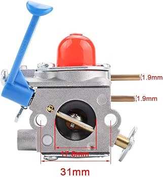
The carburetor is a crucial component in small engines, responsible for mixing air and fuel in the correct proportions for optimal performance. Understanding its structure and how to adjust it can significantly enhance the efficiency and longevity of the equipment. This guide will delve into the various components of a carburetor and provide insights into the adjustment processes to ensure smooth operation.
Key Components of the Carburetor
A typical carburetor consists of several vital parts, each serving a specific function. Familiarizing yourself with these components can help diagnose issues and facilitate effective adjustments.
| Component | Description |
|---|---|
| Throttle Valve | Regulates the flow of air and fuel mixture into the engine. |
| Float Chamber | Maintains a constant level of fuel for consistent operation. |
| Jet | Controls the amount of fuel that enters the airflow. |
| Mixture Screw | Adjusts the air-fuel ratio for optimal combustion. |
| Choke Valve | Restricts airflow to enrich the fuel mixture during starting. |
Adjustment Techniques
Proper adjustment of the carburetor is essential for achieving peak performance. Follow these basic techniques:
- Start with the engine at operating temperature.
- Adjust the mixture screw to find the optimal air-fuel ratio.
- Set the idle speed using the throttle valve to ensure smooth operation.
- Regularly check and clean the jet to prevent clogging.