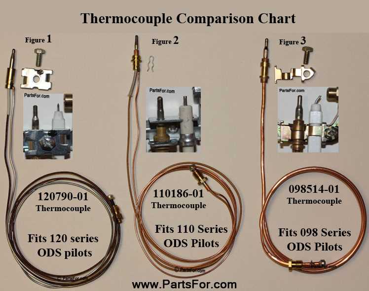
In the realm of climate control, a comprehensive understanding of the various elements that contribute to effective warmth generation is essential. Each segment of the assembly plays a crucial role, ensuring the system operates efficiently and reliably. By familiarizing oneself with these elements, users can enhance their overall experience and ensure optimal functionality.
The interplay of these components is vital for achieving a cozy environment, especially during colder seasons. Knowing how each element interacts can aid in troubleshooting potential issues and maintaining the system’s performance over time. This knowledge empowers individuals to make informed decisions regarding maintenance and repairs.
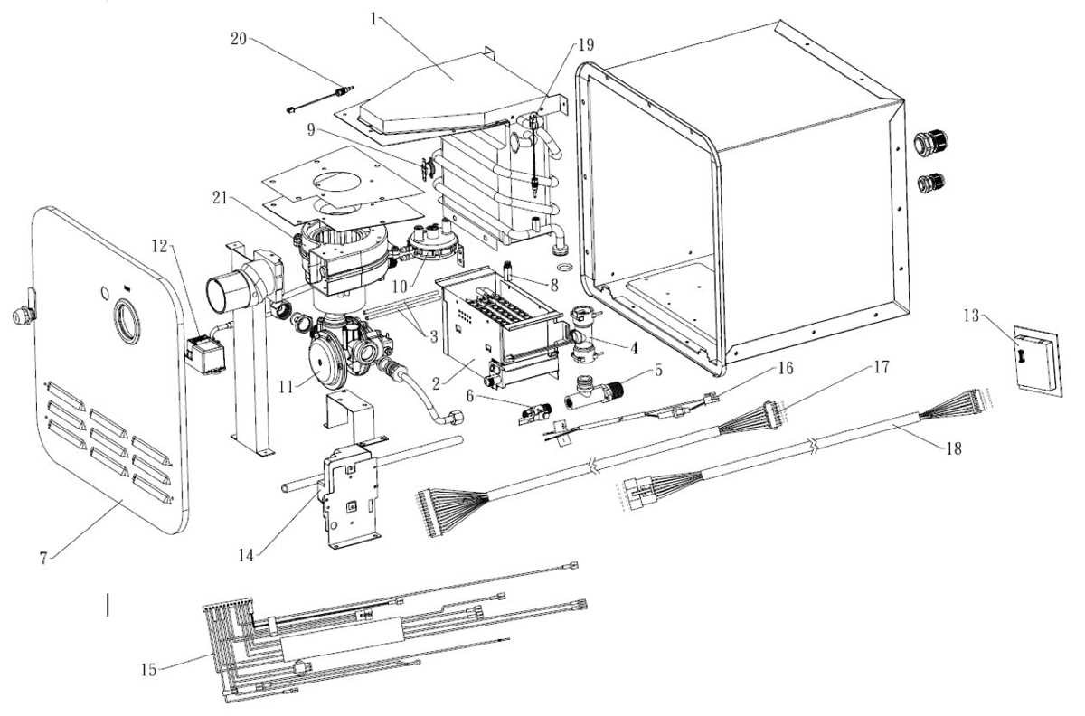
Moreover, a visual representation of these components can greatly assist in grasping their arrangement and function. Such illustrations provide a clearer insight into how the individual elements work together seamlessly, creating a cohesive unit dedicated to delivering comfort. Understanding this intricate relationship fosters a deeper appreciation for the technology behind modern heating solutions.
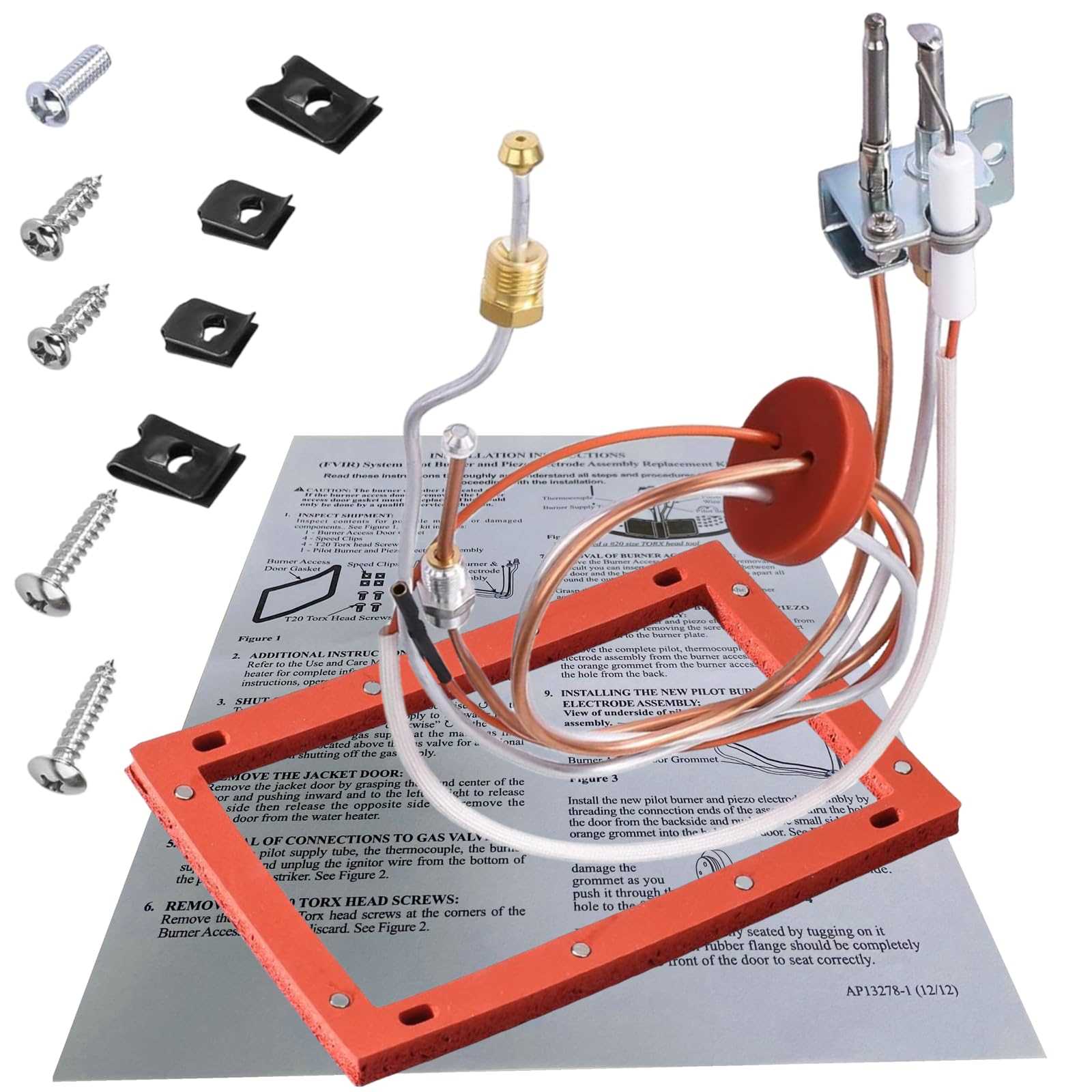
This section aims to provide a comprehensive overview of the essential elements that contribute to the functionality of heating appliances. Understanding these components is crucial for maintenance, troubleshooting, and ensuring optimal performance.
Key Elements of Heating Appliances
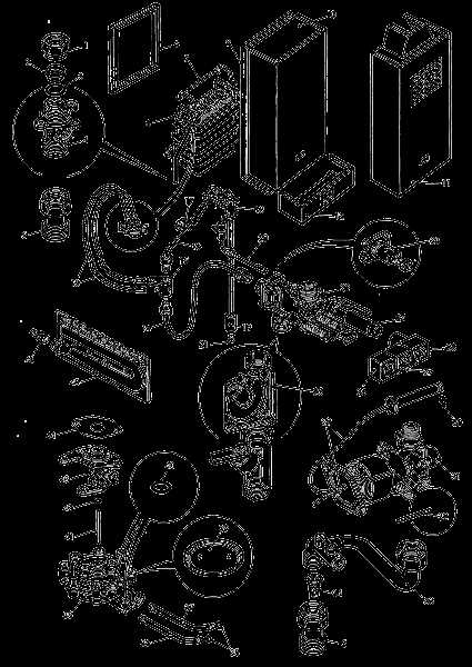
- Burner Assembly
- Ignition System
- Thermostat Control
- Flue Venting
- Fuel Supply Line
Each of these elements plays a vital role in the operation and efficiency of the device. Below is a brief explanation of each component:
- Burner Assembly: This is where the combustion process occurs, converting fuel into heat energy.
- Ignition System: Responsible for initiating the combustion process, ensuring a safe and efficient start-up.
- Thermostat Control: Monitors and regulates the temperature, maintaining comfort levels within the space.
- Flue Venting: Ensures that harmful gases produced during combustion are safely expelled from the appliance.
- Fuel Supply Line: Delivers the necessary fuel to the burner assembly for efficient operation.
Familiarizing oneself with these components enhances the understanding of how heating appliances operate, enabling users to recognize potential issues and implement appropriate solutions.
Main Parts of a Gas Heater
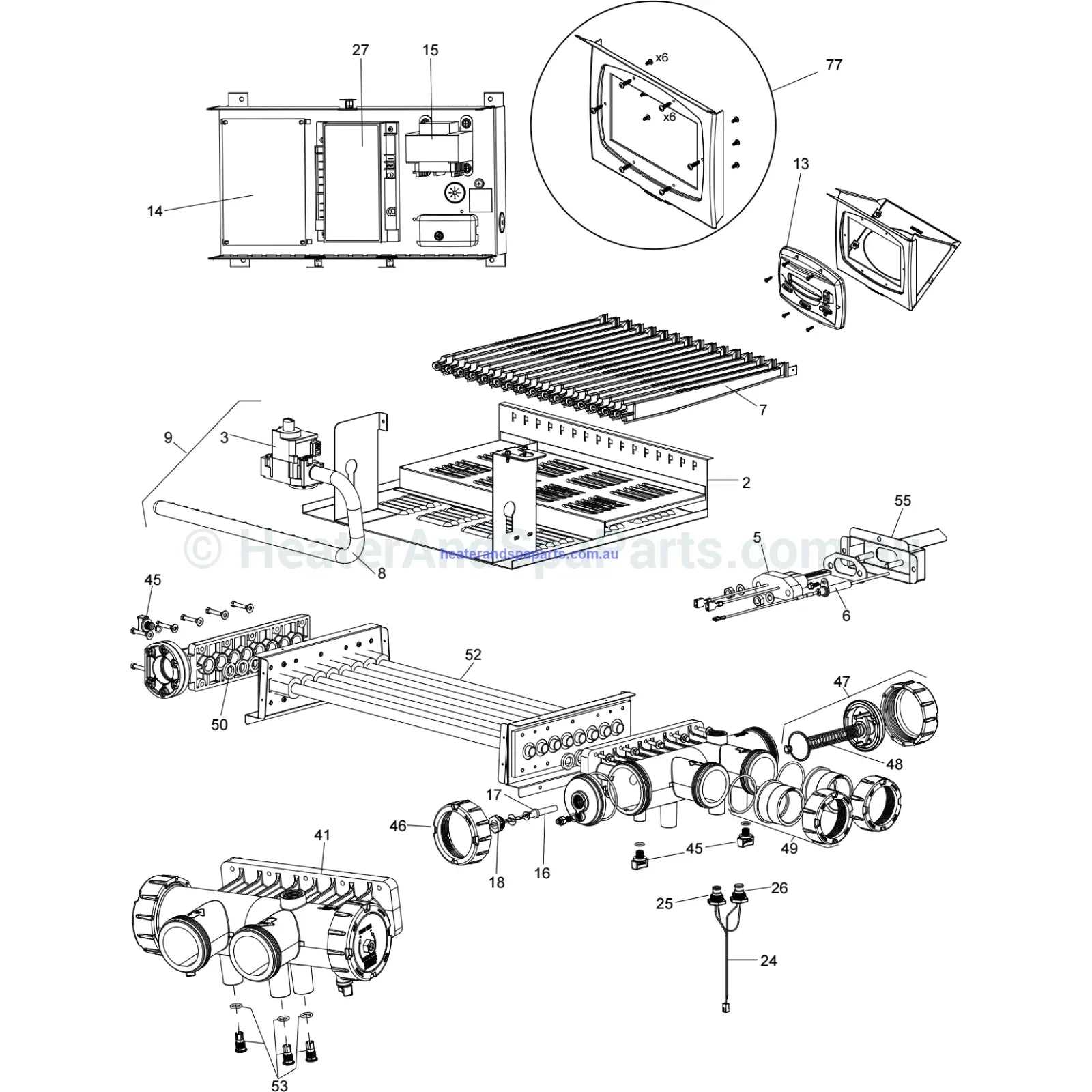
The central heating system is made up of multiple interconnected components, each designed to fulfill a specific function. These elements work in harmony to ensure efficient warmth distribution and maintain a comfortable environment. Understanding the key elements can help with maintenance and troubleshooting.
| Component |
Description |
| Burner |
This is responsible for generating the necessary energy by igniting fuel. It acts as the starting point for the heating process. |
| Thermostat |
Serves as a control mechanism, regulating the temperature by switching the system on and off based on the desired warmth level. |
| Heat Exchanger |
Transfers the generated warmth to the circulating air, ensuring it reaches the desired temperature before being distributed. |
How Gas Heaters Operate Efficiently
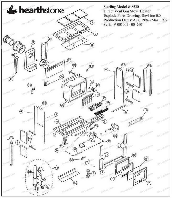
Efficient thermal systems function by converting energy into heat while minimizing waste. The process involves drawing in air, where combustion occurs to generate warmth. This method is controlled and regulated to ensure a steady output while maintaining safety and energy conservation.
Combustion and Heat Generation
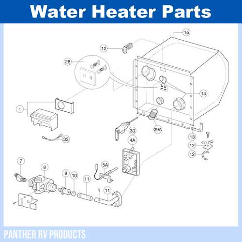
The core of the operation is the burning of fuel, which produces warmth. The fuel is mixed with air in precise proportions to ensure optimal burning. This balance is crucial for both energy efficiency and reducing emissions. By using advanced technologies, modern systems can achieve higher performance with less fuel.
Heat Distribution and Regulation
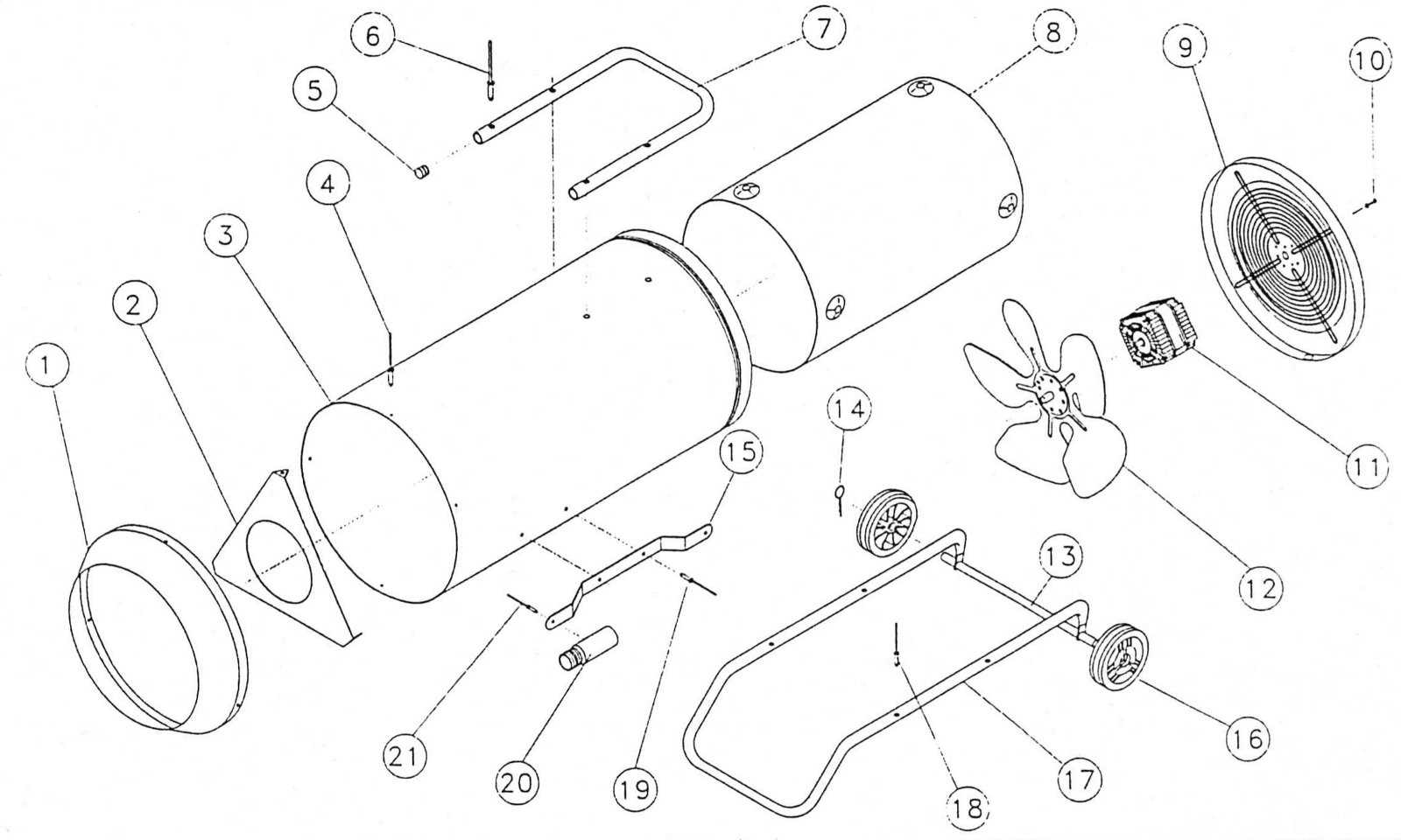
Once warmth is generated, it is transferred through a series of channels or ducts, depending on the system’s design. To maximize efficiency, sensors and control mechanisms adjust the temperature and airflow. This process helps maintain a comfortable environment while ensuring minimal energy is wasted.
Importance of Each Component
Understanding the function of individual elements within a heating system is crucial for ensuring both its performance and safety. Each part plays a unique role, working in unison to deliver optimal results. A deeper knowledge of these components helps in recognizing potential issues and maintaining efficiency.
Main Elements and Their Functions
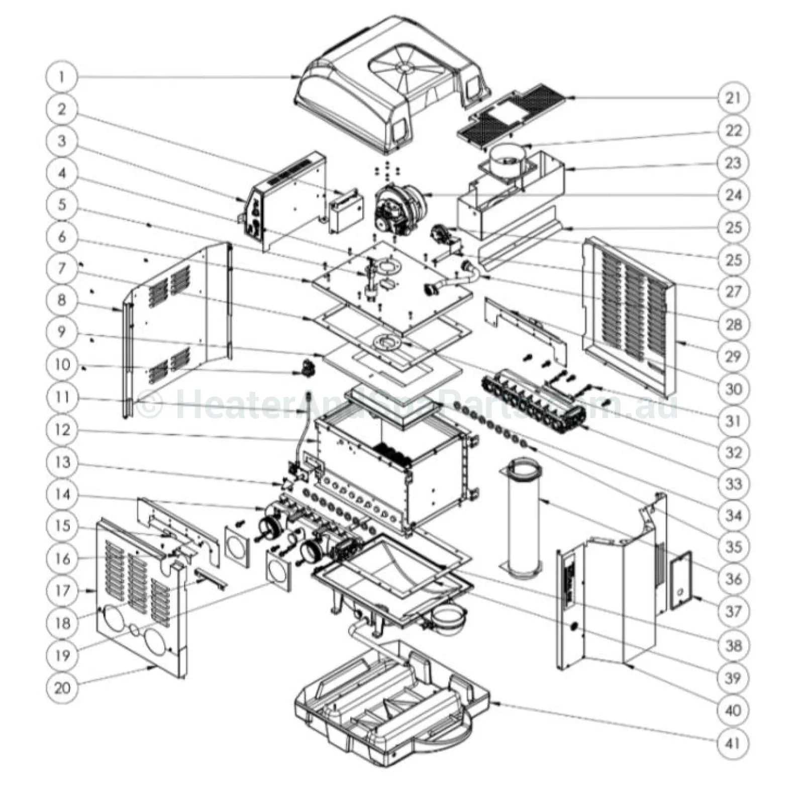
- Control Unit: This mechanism ensures the safe operation by regulating the overall performance. Its precision is vital for proper functioning.
- Valves: These devices manage the flow, ensuring that the system operates smoothly and without interruptions. They are essential for balance and control.
- Burning Mechanism: This section is responsible for generating the necessary warmth. Its stability and reliability are key for maintaining a consistent output.
Why Maintenance Matters
- Longevity: Regular inspection of these individual components ensures that the system remains functional for a longer time.
- Efficiency: Well-maintained elements lead to energy conservation and a reduction in overall costs.
- Safety: Properly working parts minimize risks,
Common Issues with Gas Heater Parts
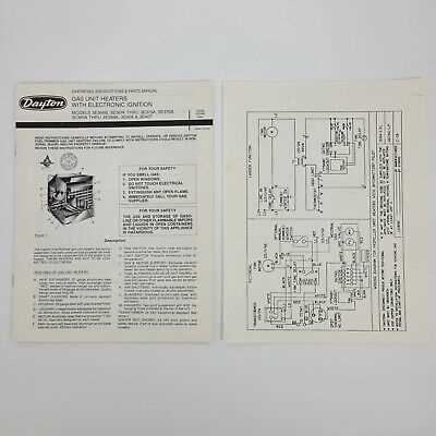
There are a variety of challenges that can arise when dealing with heating systems, often due to wear and tear or malfunctioning components. Understanding the typical problems associated with these devices can help ensure they operate efficiently and safely.
Blockages and Airflow Problems: One of the frequent complications is restricted airflow, which can reduce efficiency and potentially cause overheating. This can be due to obstructions in the venting system or dust accumulation over time.
Ignition Failures: Another prevalent issue is failure to ignite properly, which may result from faulty ignition mechanisms or electrical malfunctions. This can cause the system to fail to produce warmth consistently.
Thermostat Malfunctions: Inaccurate temperature regulation can occur if the thermostat becomes uncalibrated or damaged, leading to poor climate control. It is essential to ensure the sensor remains accurate to avoid discomfort or energy inefficiency.
Leaking Connections: Loose or damaged fittings can cause leakage, which is not only inefficient but also dangerous
Maintenance Tips for Gas Heaters
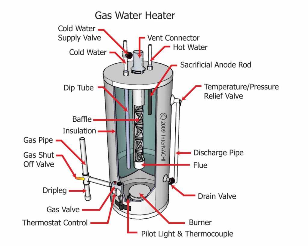
Regular upkeep is essential for ensuring the longevity and efficient operation of your home heating device. By performing routine checks and simple tasks, you can prevent common issues and ensure optimal performance throughout the colder months.
Inspecting and Cleaning Components
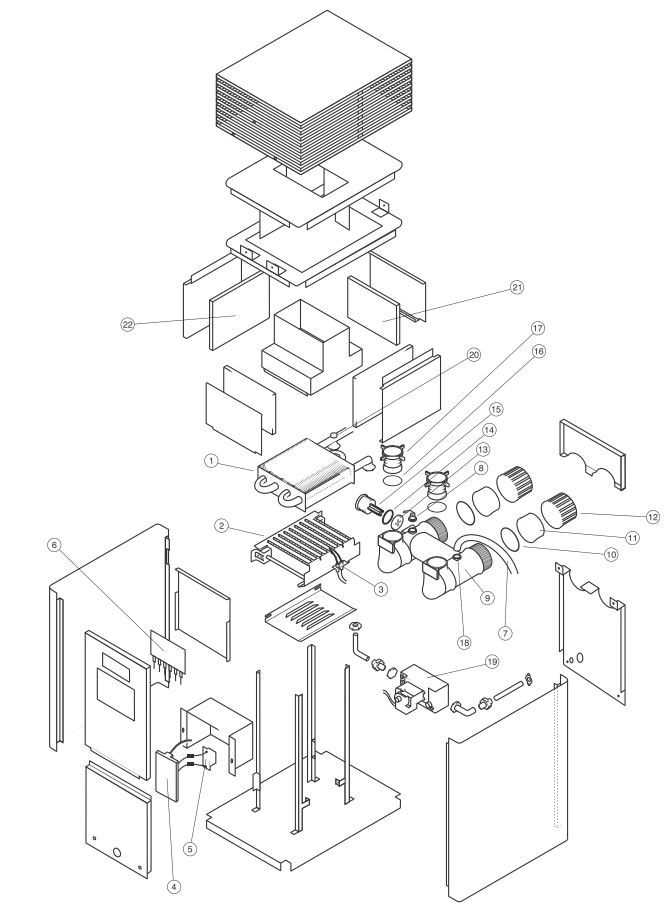
It’s important to frequently inspect the key elements of your unit. Dust, debris, and other particles can accumulate over time, potentially causing blockages or inefficiencies. Make sure to remove any buildup to allow smooth air circulation.
- Check the vents for obstructions and clear them regularly.
- Clean or replace filters as needed to maintain proper airflow.
- Inspect any exposed wiring or connections to ensure they are secure and free from damage.
Regular Professional Servicing
While some tasks can be done at home, scheduling periodic professional
Safety Features in Gas Heating Systems
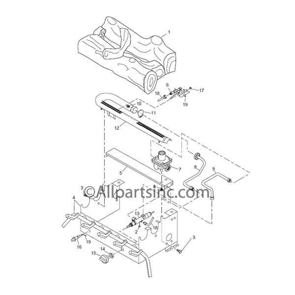
Modern thermal systems incorporate various protection mechanisms to ensure the wellbeing of users and the environment. These measures are designed to prevent accidents and maintain stable performance under different conditions.
- Automatic Shutoff Mechanism: This feature is crucial for preventing overheating or operation in unsafe situations. When sensors detect unusual conditions, the system halts its activity to avoid damage.
- Ventilation Monitoring: Proper air circulation is vital for the system’s efficiency. Monitoring devices ensure that airflow remains optimal, reducing risks associated with poor ventilation.
- Flame Detection Sensors: These sensors ensure that the combustion process occurs safely by monitoring the presence and stability of the flame. If inconsistencies are detected, the system will disable itself.
- Carbon Monoxide Detection: In case of incomplete combustion, sensors will detect harmful emissions and automatically shut down the system, protecting users from dangerous gases
Diagnosing Problems with Diagrams
Understanding how to identify issues in complex systems often starts with visual representations. These visual guides help in pinpointing malfunctioning components and understanding the flow of operations. By reviewing these depictions, one can trace possible faults and predict where repairs might be necessary.
Breaking down issues can be much easier when you have a clear map of how everything connects. This method allows technicians to systematically approach troubleshooting, examining each segment of the system step by step.
Another important aspect is recognizing common failure points within the system. Diagrams offer a visual reference to compare what’s functioning versus what might need attention. By using these visual tools effectively, identifying the root cause of malfunctions becomes a more structured and efficient process.
Upgrading Gas Heater Components
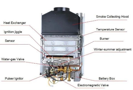
Enhancing the performance of your heating system requires thoughtful replacement of key elements. By selecting modern, more efficient pieces, you can significantly improve the overall functionality and lifespan of your device. Whether it’s improving energy efficiency or ensuring smoother operation, updating older parts with newer versions can make a noticeable difference.
Choosing the Right Components
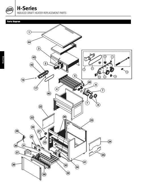
When upgrading, it’s essential to identify which areas of the system could benefit most from newer technology. Key improvements often involve controls, ignitors, or safety mechanisms that can enhance both convenience and reliability. Newer models may offer better durability or higher performance standards compared to older ones.
Installation and Compatibility
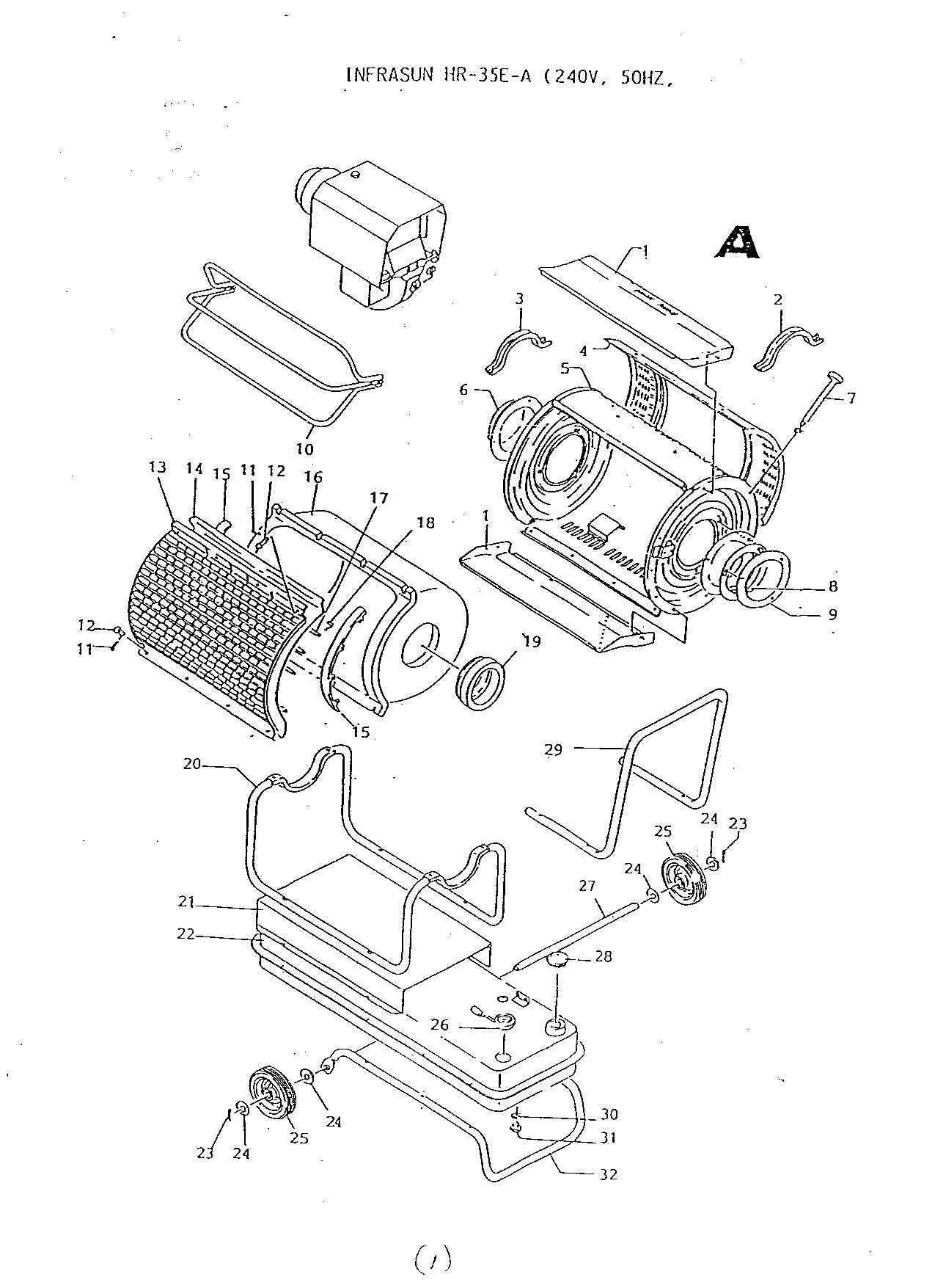
Before starting any upgrades, it’s crucial to ensure that the new components are compatible with the existing setup. Professional advice or guidance can help to avoid potential mismatches, ensuring that the installation process goes smoothly and that the upgraded system functions as intended. Proper integration of these elements is key to achieving the desired improvements.


