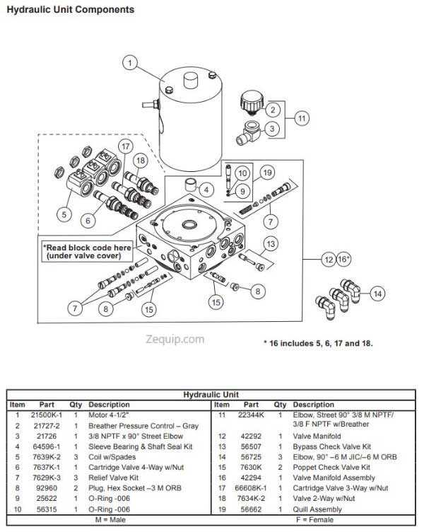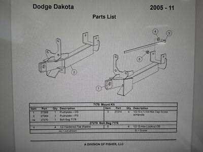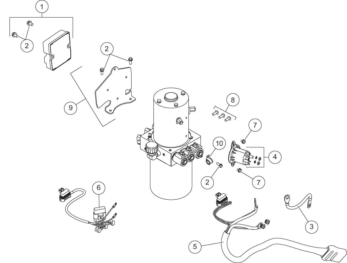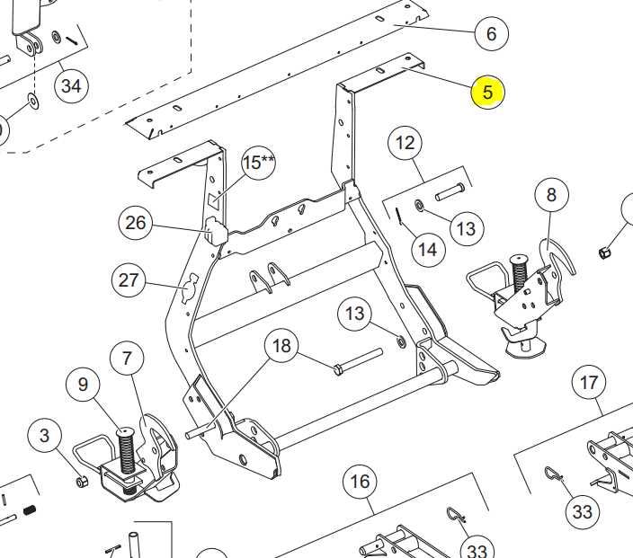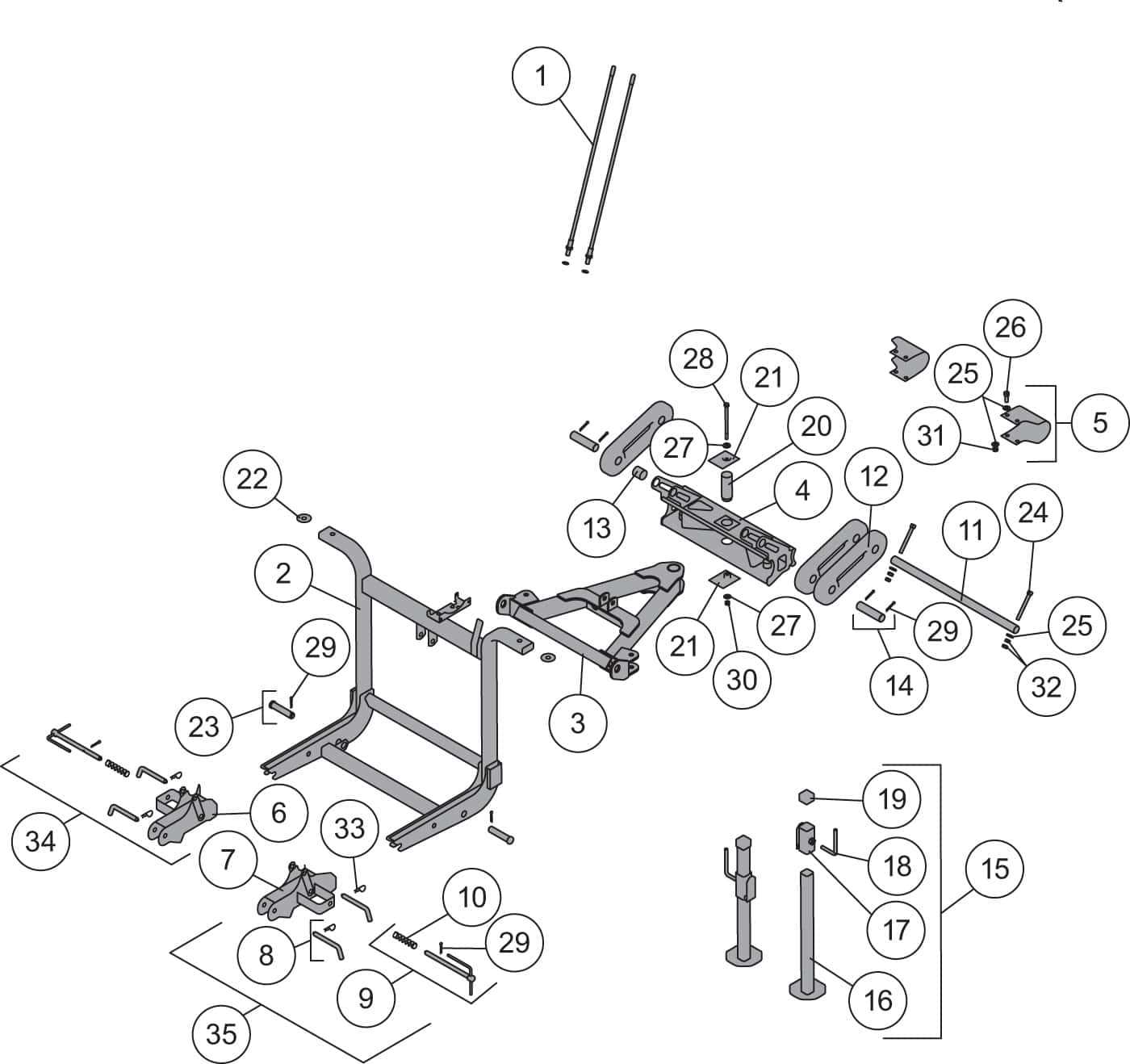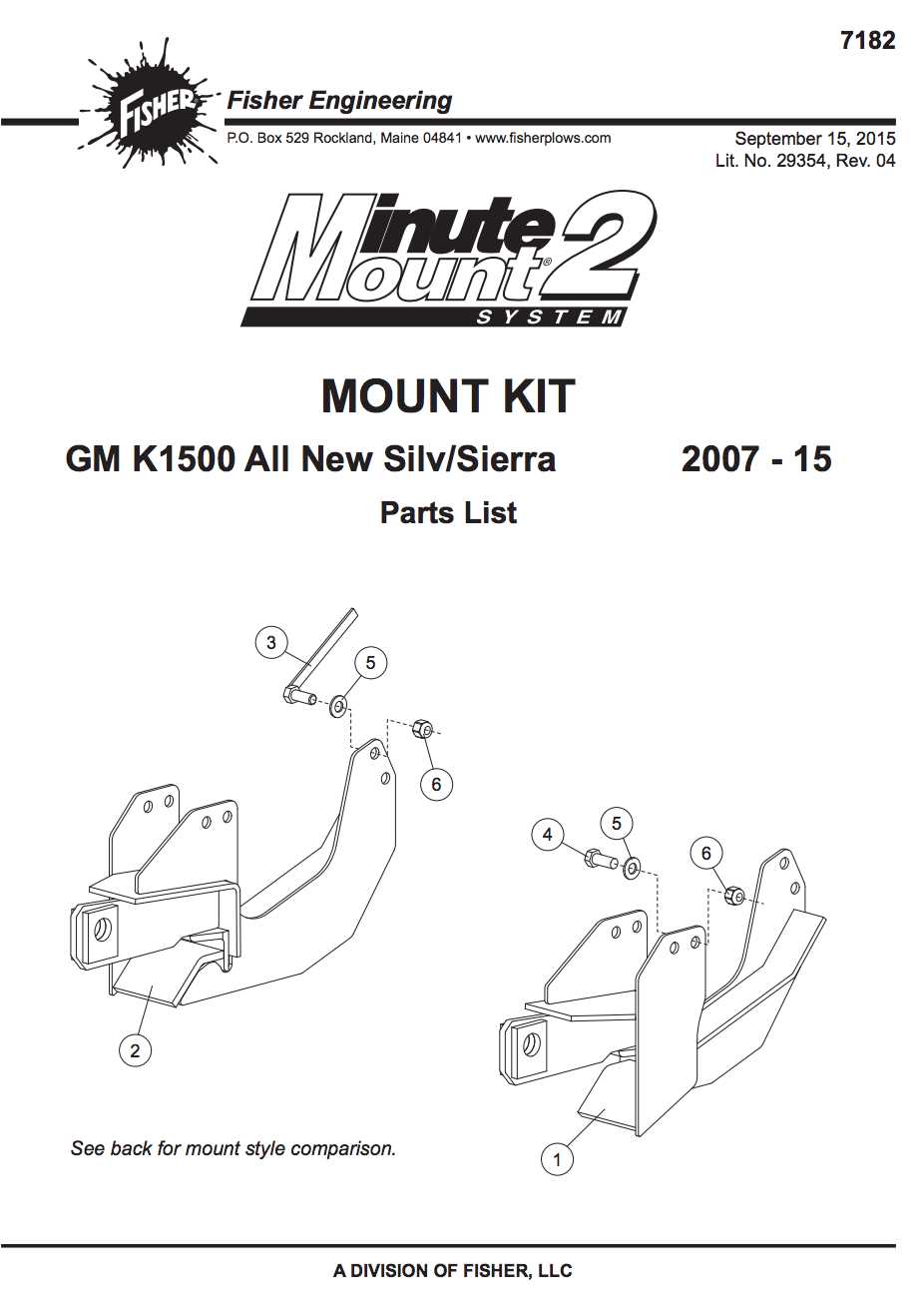
When it comes to winter maintenance, having reliable equipment is crucial. Understanding the layout and configuration of your snow-clearing system can significantly enhance its efficiency and performance. Proper knowledge of its individual elements and how they interconnect will help ensure smoother operation during those demanding tasks.
The breakdown of these systems often includes various essential units that work together to deliver precise functionality. Recognizing each component’s role and the connections between them can prevent common issues, making maintenance straightforward and troubleshooting more intuitive. By exploring the full arrangement of this setup, you can optimize your approach to winter conditions.
For anyone involved in handling or repairing these systems, knowing the specific arrangement of elements is key. It not only assists in identifying potential problem areas but also supports effective upgrades or replacements. The right insight into how everything fits together can lead to a more reliable and robust snow management solution.
 tags, without repeating phrases or similar words: Understanding Plow Mounting Components”>
Understanding the assembly of the equipment’s connection elements is essential for both installation and maintenance. These components work in unison to provide stability and efficiency during operation. Knowing their layout can significantly enhance the setup process, ensuring all parts align properly and function as intended.
- Identifying Key Structural Elements
- Exploring Connection Mechanisms
- Analyzing Load-Bearing Support Sections
- Inspecting Control Linkages and Their Role
- Examining the Alignment Systems for Precision
- Reviewing Safety Locking Devices and Their Functions
- Understanding Component Durability and Maintenance
- Optimizing Installation Techniques for Reliability
This breakdown offers a clear perspective on the various segments involved, highlighting how each part contributes to overall performance and durability
Identifying Key Attachment Elements
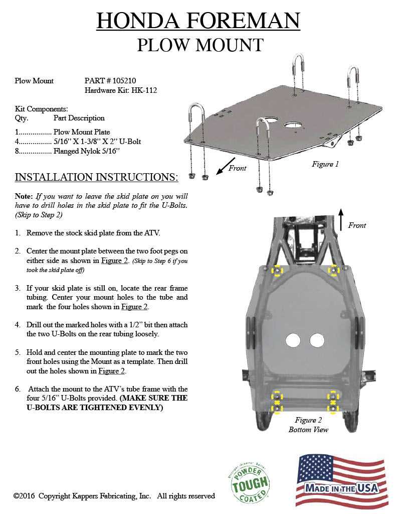
Understanding the critical connection points of a mechanical assembly is crucial for ensuring reliable performance. Recognizing these components helps in achieving a secure fit and enhances the stability of the overall system. Below, we’ll break down some of the essential elements involved in this process.
Main Connection Points
The primary connection areas play a significant role in maintaining the structural integrity of the equipment. These points are engineered to handle substantial forces, ensuring that the assembly remains intact even under stress.
Supportive Components
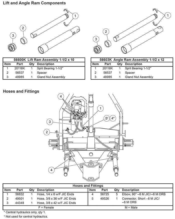
Supportive elements act as reinforcements to the main connections, providing additional stability and balance. They are designed to distribute loads evenly, reducing the risk of mechanical failure.
| Element Type | Function | Importance | |||||||||||||||||
|---|---|---|---|---|---|---|---|---|---|---|---|---|---|---|---|---|---|---|---|
| Primary Fasteners | Secure the main joints | High | |||||||||||||||||
| Reinforcement Brackets | Support structural integrity | Medium | |||||||||||||||||
| Alignment Pins | Ensure proper positioning |
| Component | Wire Color | Function |
|---|---|---|
| Battery | Red | Positive Supply |
| Ground | Black | Negative Supply |
| Control Switch | Green | Activation Signal |
| Motor | Yellow | Power Supply |
| Light | White | Indicator Function |
Troubleshooting Wiring Issues

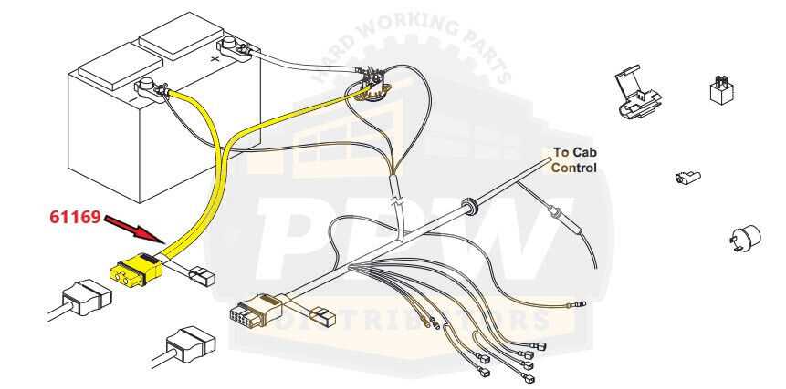
When facing challenges with electrical connections in your equipment, identifying the source of the problem is crucial. Wiring issues can manifest in various forms, such as poor connections, shorts, or broken wires. Understanding the symptoms can help narrow down the potential causes and facilitate an effective resolution.
First, inspect all connections to ensure they are secure and free from corrosion. Loose or oxidized terminals can disrupt the flow of electricity, leading to malfunction. Next, check for any visible signs of damage along the wiring. Frayed or cut wires can create shorts, preventing the system from operating properly. Additionally, utilize a multimeter to test the continuity of the wires and confirm that electrical signals are transmitting as intended.
If issues persist, consider the components associated with the wiring system. Relays and switches can also contribute to electrical failures. Testing these parts for functionality will help determine if they require replacement. Regular maintenance and inspections can prevent wiring problems and enhance the longevity of your equipment.
Lighting System Components
The illumination mechanism of a snow-clearing apparatus is vital for ensuring visibility during adverse weather conditions. Understanding the essential elements involved can enhance safety and functionality, allowing operators to effectively manage their equipment in low-light environments.
Essential Elements
At the core of the lighting mechanism are the lamps, which emit bright light to illuminate the area in front of the vehicle. These components vary in type, including halogen and LED options, each offering distinct benefits in terms of brightness and energy consumption. Proper positioning of these fixtures is crucial for maximizing visibility and reducing blind spots.
Wiring and Control Systems
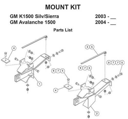
In addition to the lamps, the wiring system plays a significant role in connecting the lights to the vehicle’s electrical network. This includes switches and relays that control the operation of the lighting. A reliable control mechanism ensures that the illumination can be activated or deactivated as needed, contributing to the overall efficiency of the equipment.
Examining Illumination Elements
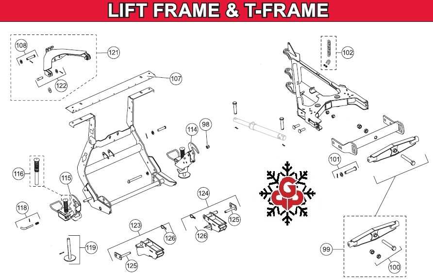
Understanding the various components that contribute to effective lighting in snow removal equipment is essential for optimizing performance and safety. These elements play a crucial role in enhancing visibility during challenging weather conditions, ensuring operators can work efficiently and safely.
Light Types: Different lighting systems, such as halogen, LED, and xenon, offer unique benefits regarding brightness, energy consumption, and longevity. Evaluating these options helps users choose the best fit for their operational needs.
Placement Considerations: The positioning of illumination fixtures is vital for achieving optimal light distribution. Strategically placed lights can reduce shadows and illuminate critical areas, allowing for a clearer view of the working environment.
Maintenance Tips: Regular maintenance of lighting components, including cleaning lenses and checking for damage, ensures maximum efficiency. Keeping these elements in good condition not only enhances visibility but also prolongs the lifespan of the equipment.
