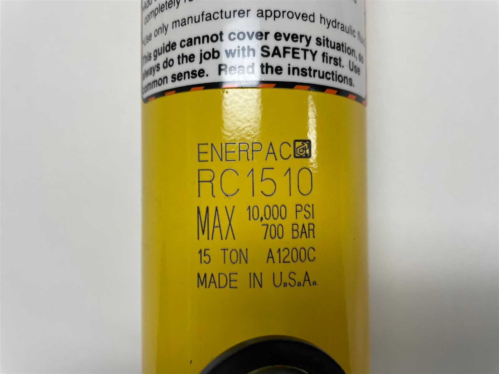
In the world of hydraulic systems, a comprehensive overview of the various components is essential for optimal functionality and maintenance. Grasping the intricate arrangements and relationships between different elements can significantly enhance operational efficiency and troubleshooting processes.
Detailed visual representations serve as invaluable tools for technicians and engineers alike. They provide clarity and facilitate a deeper understanding of how each piece interacts within the broader system, ultimately leading to improved performance and longevity.
By exploring these representations, one can delve into the intricacies of assembly and identify potential areas for improvement. Such insights are vital for anyone aiming to achieve the ultimate reliability in hydraulic applications.
Understanding Enerpac Parts Diagram
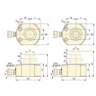
Grasping the intricacies of component illustrations is essential for effective maintenance and repair tasks. These visual guides serve as invaluable resources, enabling users to identify and understand each element’s role within a mechanical assembly. A clear comprehension of these representations can significantly enhance operational efficiency and safety.
Importance of Visual Guides
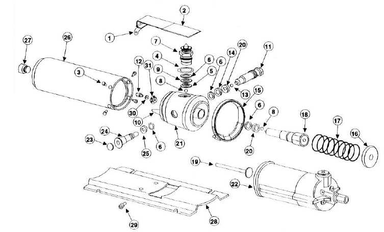
Visual aids facilitate quicker diagnostics and repairs, reducing downtime. By providing a clear reference, they help technicians navigate complex systems, ensuring that each element is correctly addressed during service.
Navigating Component Illustrations
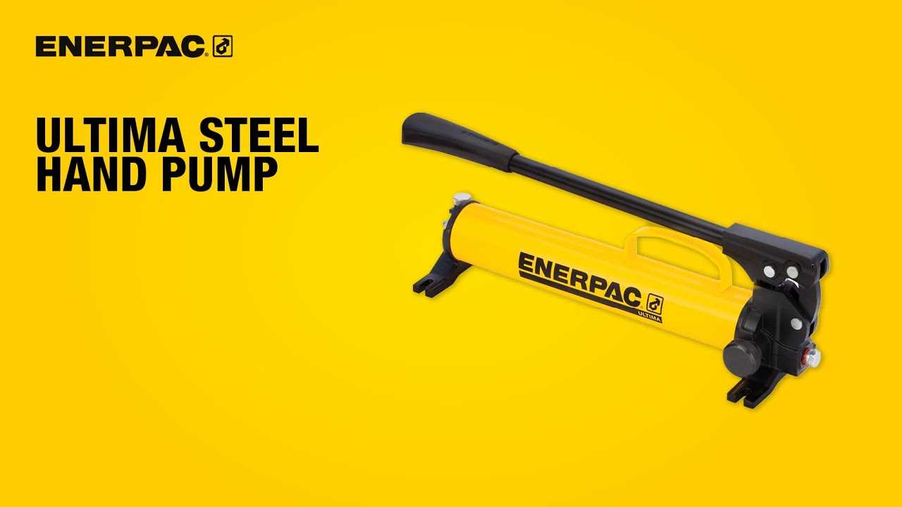
Familiarity with these visuals allows users to pinpoint specific elements and comprehend their functions within the entire system. This knowledge not only streamlines the repair process but also empowers users to make informed decisions regarding maintenance and replacements.
Components of Enerpac Equipment

The efficiency and functionality of hydraulic machinery depend on a variety of crucial elements that work in harmony. Understanding these components is essential for optimal performance and maintenance. Each part plays a vital role in ensuring that the equipment operates smoothly and effectively.
Hydraulic Cylinders are fundamental for generating force. These robust tubes are designed to convert hydraulic energy into mechanical power, allowing for heavy lifting and pushing tasks.
Power Units serve as the heart of the system, providing the necessary pressure and flow to the cylinders. These units can vary in size and capacity, depending on the specific application requirements.
Control Valves play a key role in directing the flow of hydraulic fluid, ensuring that the system functions according to user input. They regulate speed and movement, offering precision in operation.
Hoses and Fittings are essential for connecting various components, allowing the hydraulic fluid to flow seamlessly between them. Their durability and flexibility are critical for maintaining system integrity.
Accessories, such as adapters and pressure gauges, enhance the functionality of the machinery. These additional tools provide valuable information and versatility, making operations more efficient.
By delving into the significance of each element, users can achieve a deeper understanding of their hydraulic systems, ultimately leading to improved performance and longevity.
How to Read a Parts Diagram
Understanding a schematic representation of components is essential for effective maintenance and troubleshooting. Such illustrations provide a visual guide to the various elements of a mechanical system, allowing users to identify parts and their relationships within the assembly.
To effectively interpret these illustrations, follow these key steps:
- Familiarize Yourself with Symbols:
- Identify common symbols used to represent different components.
- Look for legends or keys that explain the meanings of specific icons.
- Study the Layout:
- Observe the arrangement of components to understand how they connect.
- Pay attention to the flow of operation indicated in the design.
- Reference Part Numbers:
- Locate part numbers associated with each item for easy identification.
- Use these numbers to cross-reference with catalogs or manuals.
- Understand the Annotations:
- Read any accompanying notes that provide additional information or instructions.
- Take note of any warnings or special handling instructions.
By following these guidelines, you can enhance your understanding of the system, leading to more efficient repairs and maintenance tasks.
Common Parts in Enerpac Systems
Understanding the essential components within hydraulic systems is crucial for optimal performance and reliability. These elements work together to ensure smooth operation and effective power transmission in various industrial applications. Recognizing the key elements can aid in maintenance, troubleshooting, and enhancing overall system efficiency.
Key Components
Among the fundamental elements are hydraulic cylinders, which convert hydraulic energy into mechanical force. They play a vital role in lifting, pushing, or pulling heavy loads. Additionally, pumps are essential for generating hydraulic pressure, ensuring fluid movement throughout the system. Proper selection and maintenance of these components are critical for achieving desired operational outcomes.
Supporting Elements

Moreover, valves control the flow of hydraulic fluid, directing it to various parts as needed. This regulation is essential for maintaining system stability and responsiveness. Hoses and fittings also play an integral part, providing the necessary connections for fluid transfer while withstanding high pressure. Understanding these supporting elements enhances the capability to optimize system performance and longevity.
Maintenance Tips for Enerpac Equipment
Regular upkeep of hydraulic machinery is essential to ensure optimal performance and longevity. By following specific guidelines, operators can minimize downtime and enhance efficiency. Here are some key practices to maintain your equipment effectively.
| Tip | Description |
|---|---|
| Regular Inspection | Check for leaks, wear, and damage on all components frequently. |
| Fluid Management | Maintain proper fluid levels and replace hydraulic fluid as needed to prevent contamination. |
| Cleanliness | Keep the machinery clean to avoid debris buildup that can affect performance. |
| Lubrication | Ensure all moving parts are adequately lubricated to reduce friction and wear. |
| Training | Provide proper training for operators to enhance safety and efficiency during use. |
Identifying Replacement Parts Quickly
Efficiently locating the necessary components for machinery can significantly reduce downtime and streamline repairs. By employing a systematic approach and utilizing visual aids, individuals can swiftly identify the required elements without unnecessary delays.
| Step | Description |
|---|---|
| 1 | Gather all relevant documentation and manuals to reference specifications. |
| 2 | Examine the equipment to pinpoint any issues or areas needing attention. |
| 3 | Utilize clear visual references to match damaged items with their equivalents. |
| 4 | Confirm part numbers and specifications for accuracy before ordering. |
Benefits of Using Accurate Diagrams
Having precise illustrations in technical documentation is crucial for enhancing understanding and efficiency. These visual representations serve as invaluable tools that simplify complex information, allowing users to grasp intricate details effortlessly. By employing accurate schematics, organizations can ensure better communication and collaboration among teams.
One of the primary advantages of utilizing detailed visuals is the reduction of errors during assembly and maintenance processes. When individuals have access to clear and correct representations, the likelihood of misinterpretation decreases significantly. This not only saves time but also minimizes costly mistakes.
| Benefit | Description |
|---|---|
| Enhanced Clarity | Visuals break down complicated concepts into understandable segments, making it easier for users to follow instructions. |
| Improved Efficiency | Clear graphics streamline workflows, enabling faster completion of tasks with fewer delays. |
| Increased Safety | Accurate visuals help identify potential hazards, ensuring that users adhere to safety protocols during operations. |
| Better Training | High-quality illustrations facilitate the onboarding process, allowing new users to learn systems quickly and effectively. |
In summary, the integration of well-crafted visuals into technical materials fosters a more productive and safe environment. Emphasizing the importance of accuracy in these representations ultimately leads to better outcomes in various operational contexts.
Where to Find Enerpac Diagrams Online
Accessing visual references for machinery components is essential for effective maintenance and repairs. Numerous online platforms provide detailed illustrations and schematics that help users identify and understand various elements of their equipment. These resources range from official manufacturer websites to dedicated technical forums and third-party distributors.
Official manufacturer websites often have comprehensive sections for manuals and visual aids, ensuring that users receive accurate and up-to-date information. Additionally, online marketplaces may feature downloadable resources alongside product listings, making it easier to find specific visuals as needed.
Technical forums and community-driven websites can also be valuable, as they frequently host shared resources and discussions about troubleshooting and repairs. Engaging with other users in these spaces can lead to discovering unique insights and lesser-known diagrams that enhance understanding.
Finally, digital libraries and archives may provide historical schematics, which can be beneficial for vintage models. Utilizing a combination of these resources will ultimately ensure that you have access to the necessary visual aids for optimal equipment performance.
Case Studies: Diagram Usage in Repairs
This section explores real-world scenarios where visual representations have played a crucial role in the repair process. By analyzing various case studies, we can understand how these tools enhance efficiency and accuracy in maintenance tasks.
Case Study 1: Hydraulic System Restoration
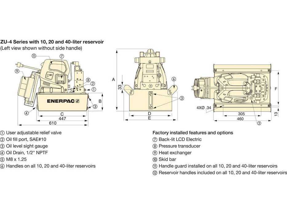
A company faced significant downtime due to a malfunctioning hydraulic system. Technicians utilized a detailed schematic to identify issues quickly, leading to a streamlined repair process. The clarity provided by the visual aid allowed them to pinpoint the malfunctioning components, resulting in a rapid restoration of operations.
Case Study 2: Pneumatic Equipment Overhaul
In another instance, a manufacturer encountered repeated failures in their pneumatic machinery. By referencing comprehensive visual guides, the maintenance team effectively traced the problems to worn-out seals. This systematic approach not only resolved the immediate issue but also established a preventive maintenance schedule.
| Case Study | Challenge | Solution |
|---|---|---|
| Hydraulic System Restoration | Downtime due to malfunction | Utilized schematic for quick identification |
| Pneumatic Equipment Overhaul | Repeated machinery failures | Referenced visual guides for effective troubleshooting |