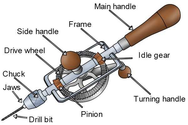
In the realm of machinery and equipment, a comprehensive grasp of each element is essential for optimal performance and maintenance. Every mechanism consists of various units that play distinct roles, ensuring that the overall system operates smoothly and efficiently. Recognizing how these individual pieces interact can significantly enhance both usability and longevity.
Whether you’re a seasoned technician or a hobbyist, familiarizing yourself with the intricate layout of your device is crucial. Each segment, from the motor to the controlling interfaces, contributes to the functionality and effectiveness of the whole. This knowledge not only aids in troubleshooting but also empowers you to make informed decisions during upgrades or repairs.
Furthermore, visual representations can simplify the understanding of these intricate relationships. By examining well-crafted illustrations, one can easily identify where each unit fits within the larger framework, fostering a deeper appreciation for the engineering involved. Such insights pave the way for more effective handling and improved maintenance practices.
Understanding Drill Components
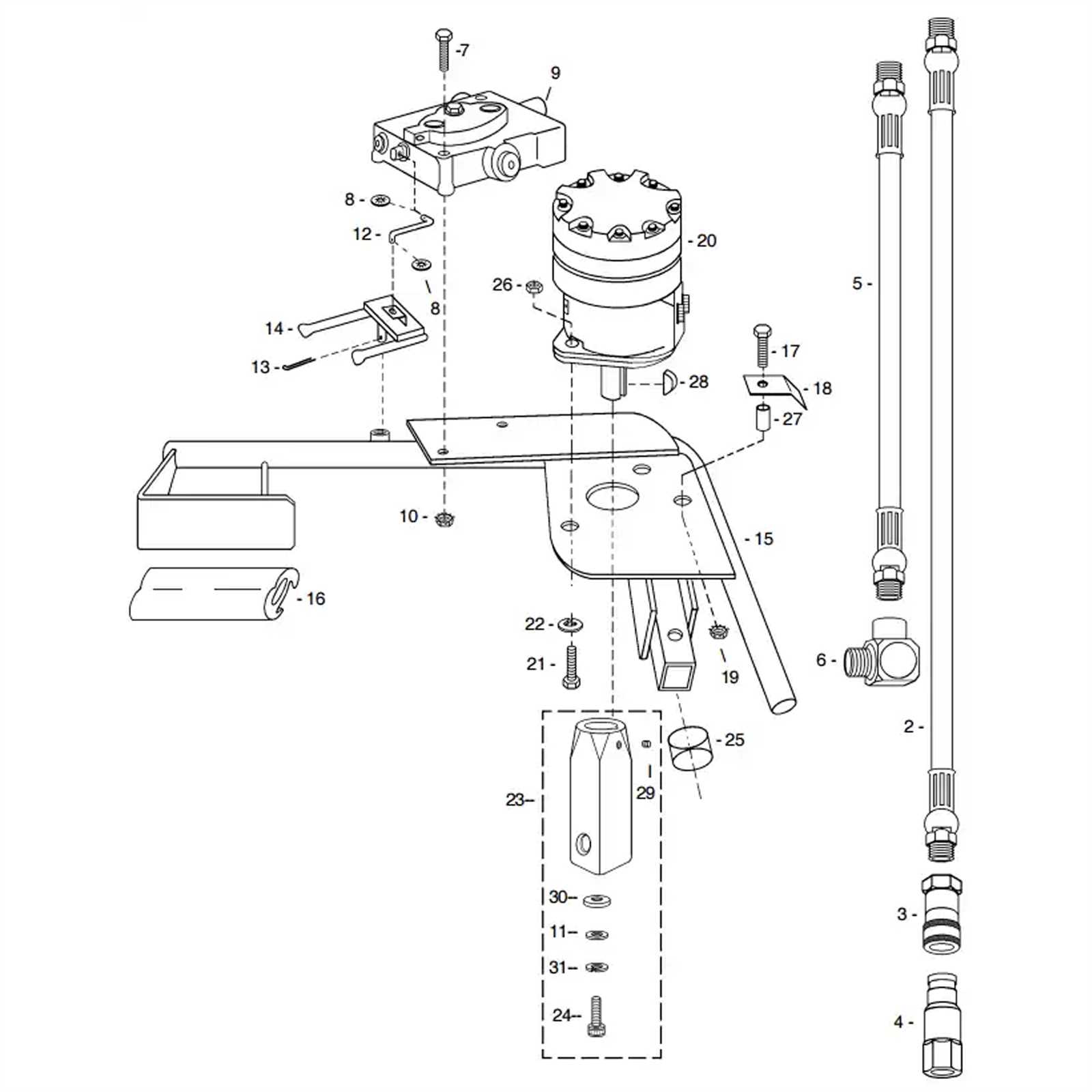
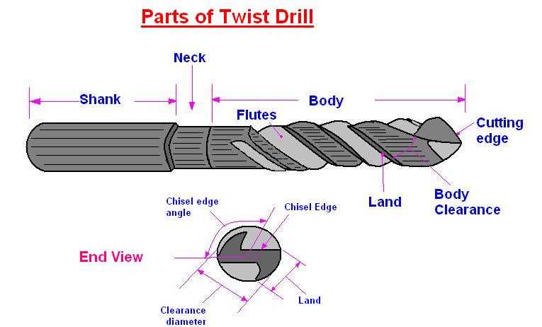
In any mechanical tool designed for boring holes, a comprehensive grasp of its elements is essential for effective operation and maintenance. Each component plays a crucial role in the functionality, ensuring precision and efficiency in various applications. Familiarity with these elements not only enhances performance but also aids in troubleshooting and repair processes.
Firstly, the motor serves as the powerhouse, driving the entire mechanism. A robust motor ensures sufficient torque, allowing for varied materials to be addressed with ease.
Secondly, the bit is a pivotal element, designed to cut through surfaces. Different designs and materials cater to specific tasks, making it essential to select the appropriate type for optimal results.
Furthermore, the chuck holds the bit securely in place, allowing for stability during operation. Its mechanism can vary, influencing how easily bits can be changed or adjusted.
Lastly, the gear mechanism allows for speed variations, enabling the user to adapt to different materials and tasks. Understanding how these components interact ultimately leads to improved proficiency and satisfaction in using the tool.
Types of Drills Available
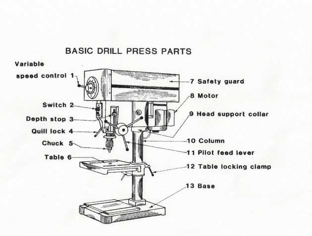
In the realm of powered tools, various models cater to diverse tasks and user preferences. Each type is designed with unique features that enhance performance and efficiency, making them suitable for specific applications in construction, woodworking, and home improvement.
Understanding the different categories can help users select the right tool for their needs. Below is a summary of the main types commonly found in the market:
| Type | Description | Applications |
|---|---|---|
| Rotary Tool | A versatile tool used for drilling, sanding, and cutting with interchangeable accessories. | Crafting, precision work, and light-duty tasks. |
| Hammer Tool | Equipped with a hammering mechanism, ideal for penetrating hard materials. | Brick, masonry, and concrete applications. |
| Impact Driver | Provides high torque for driving screws and bolts, often featuring a quick-change chuck. | Construction, assembly, and heavy-duty fastening. |
| Cordless Model | Powered by a rechargeable battery, offering portability and convenience. | General home improvement and outdoor projects. |
| Benchtop Version | Stationary tool designed for precise drilling at various angles and depths. | Woodworking and metalworking in a workshop setting. |
Choosing the right tool from this diverse lineup not only enhances productivity but also ensures the quality of work across various projects.
Essential Parts of a Drill
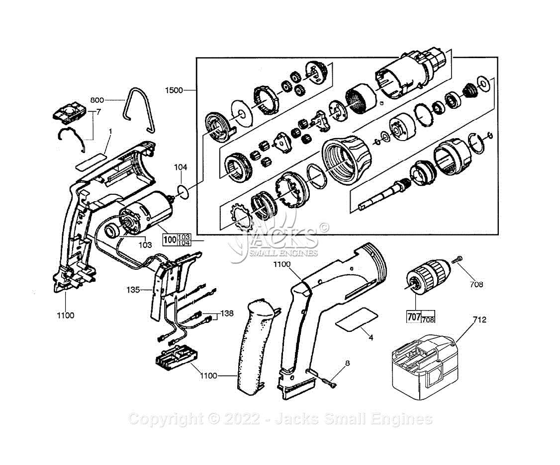
Understanding the core components of a tool designed for boring holes is crucial for effective operation and maintenance. Each element plays a significant role in ensuring efficiency, precision, and durability. Familiarity with these elements enables users to make informed decisions when selecting and utilizing such equipment.
Key Components
The foremost element is the motor, which provides the necessary power to perform tasks. Next is the chuck, a mechanism that securely holds the cutting accessory in place. Additionally, the gearbox facilitates speed adjustments, allowing for versatility in different materials. Other important features include the handle for stability and control, as well as safety mechanisms to prevent accidents.
Additional Features
Many tools also incorporate variable speed settings, enhancing adaptability to various applications. Some models include built-in lighting to illuminate work areas, while others may feature ergonomic designs for comfort during prolonged use. Understanding these functionalities contributes to maximizing performance and ensuring user satisfaction.
How to Read a Parts Diagram
Understanding a technical illustration is essential for anyone working with machinery or tools. Such visual representations provide a clear layout of components, enabling users to identify individual elements and comprehend their arrangement within the whole assembly. Mastering the ability to interpret these illustrations can significantly enhance maintenance and repair processes.
Identifying Components
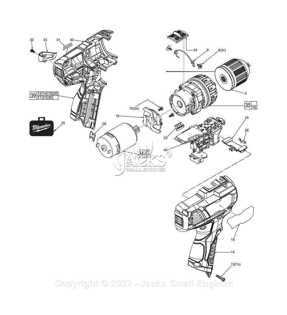
Begin by familiarizing yourself with the various symbols and notations used in the illustration. Each component is typically labeled with a unique identifier, which may correspond to a list or legend accompanying the visual. Pay attention to the scale and orientation, as these factors can influence how parts are positioned relative to one another.
Understanding Relationships
Once you have identified the individual elements, focus on their connections and interactions. Lines and arrows often indicate how parts fit together or function in relation to one another. Recognizing these relationships is crucial for troubleshooting issues or conducting repairs effectively, as it provides insight into how the assembly operates as a cohesive unit.
Common Drill Mechanisms Explained
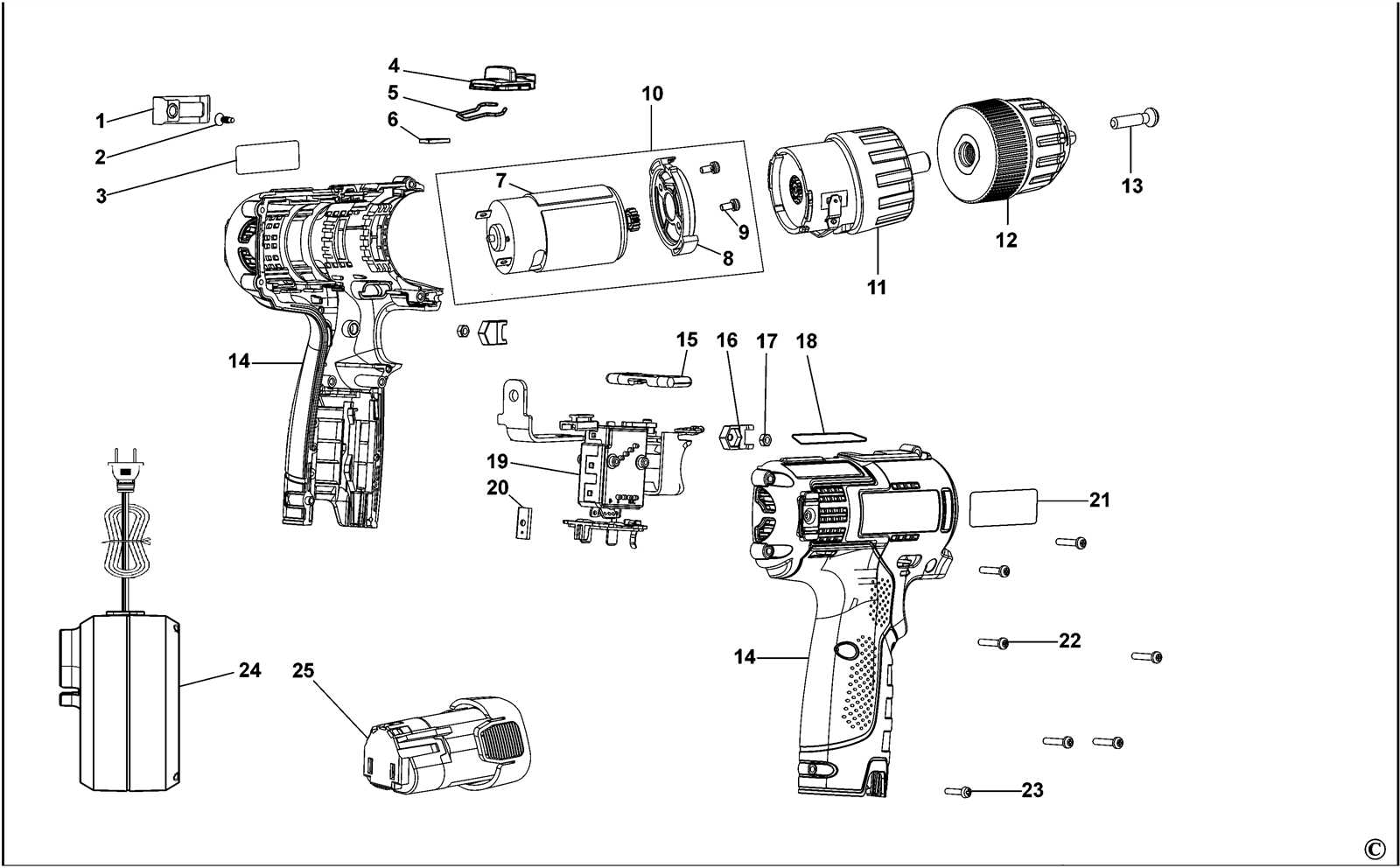
This section delves into the various mechanisms that enable the efficient functioning of rotary tools. Understanding these systems is crucial for optimizing performance and selecting the right equipment for specific tasks. Each mechanism serves a unique purpose, contributing to the overall effectiveness of the tool.
Types of Mechanisms
Rotary tools utilize several key mechanisms to facilitate movement and torque transfer. Here are some of the most commonly employed systems:
| Mechanism | Description | Application |
|---|---|---|
| Gear System | Utilizes interlocking gears to amplify torque and control speed. | Used in heavy-duty applications requiring high power. |
| Pneumatic Mechanism | Employs compressed air to create rotational motion. | Ideal for tasks requiring high speed and low torque. |
| Electromagnetic Drive | Relies on electromagnetic fields to produce movement. | Common in precision tools for delicate operations. |
| Direct Drive | Links the motor directly to the tool for immediate response. | Preferred for compact designs and quick tasks. |
Conclusion
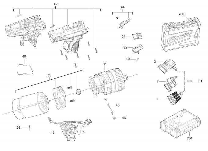
Each mechanism plays a vital role in enhancing the functionality of rotary equipment. By understanding these systems, users can make informed decisions and maximize the efficiency of their tools.
Importance of Maintenance for Longevity
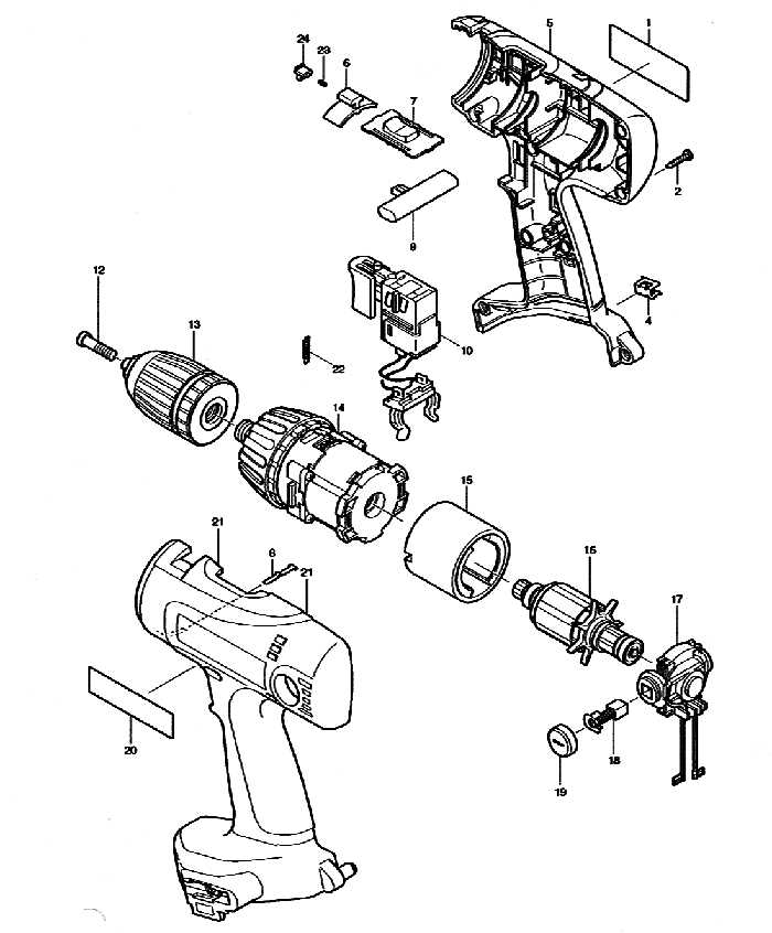
Regular upkeep is crucial for ensuring the extended lifespan of any equipment. By implementing a systematic maintenance routine, users can prevent wear and tear, enhance performance, and reduce the likelihood of unexpected failures. This proactive approach not only saves time and resources but also promotes efficiency and reliability.
Neglecting routine care can lead to cumulative damage, resulting in costly repairs and reduced functionality. Small issues, if left unaddressed, can escalate into significant problems, making timely intervention essential. Moreover, consistent maintenance fosters a safer operating environment, minimizing risks associated with malfunctioning machinery.
In addition, maintaining optimal performance through regular checks allows for the identification of areas that may require upgrades or improvements. This not only enhances the overall effectiveness of the equipment but also supports innovation and advancement in technology. Thus, a commitment to maintenance not only safeguards investments but also contributes to a culture of excellence and sustainability.
Upgrading Drill Parts for Efficiency
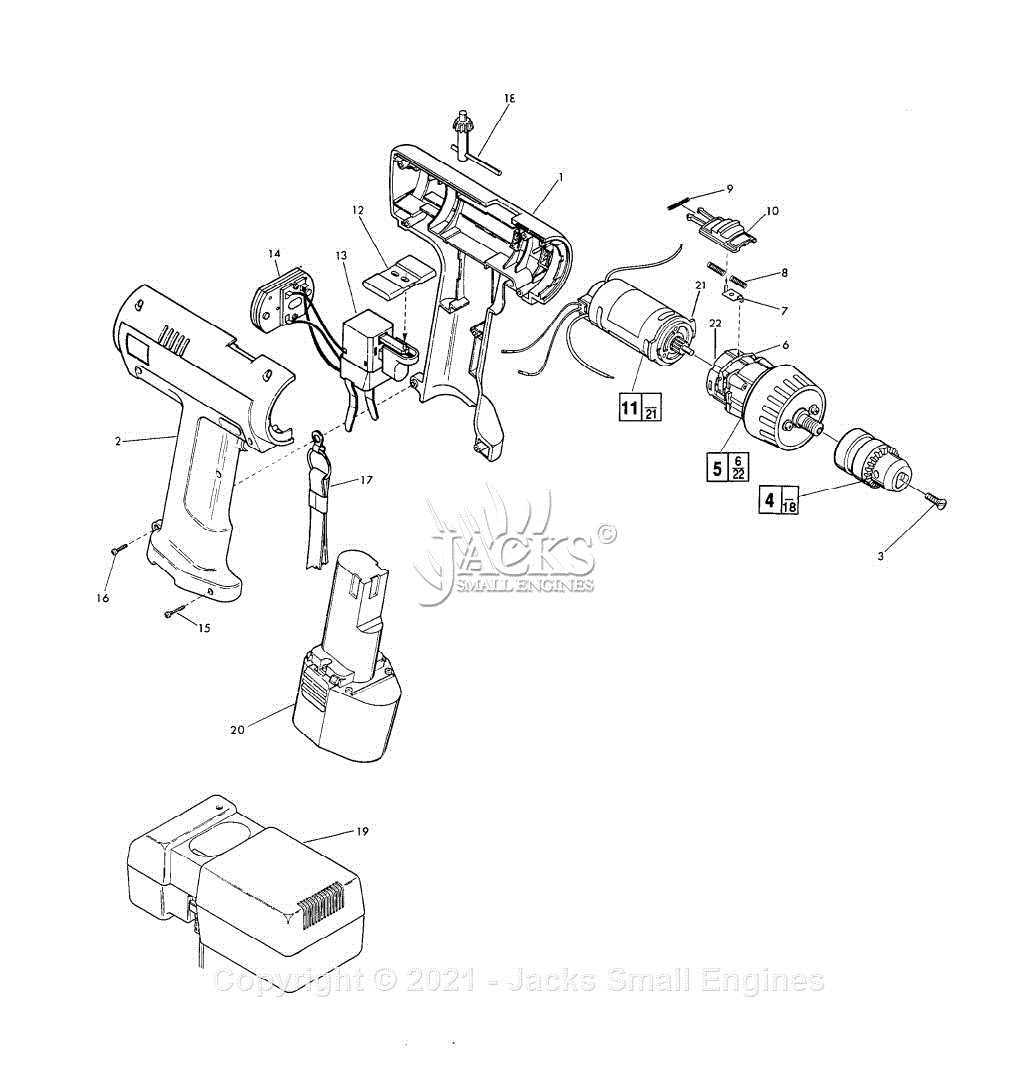
Enhancing the components of your equipment can lead to significant improvements in performance and productivity. By focusing on high-quality materials and advanced designs, users can optimize their tools for various applications. This section explores the benefits of modernizing essential elements to achieve greater effectiveness and longevity.
Key Benefits of Modernization
Investing in upgraded components offers several advantages, including increased precision, reduced wear and tear, and enhanced operational speed. Additionally, modern designs often incorporate innovations that can lead to lower energy consumption and reduced downtime, ultimately saving costs over time.
Recommended Upgrades
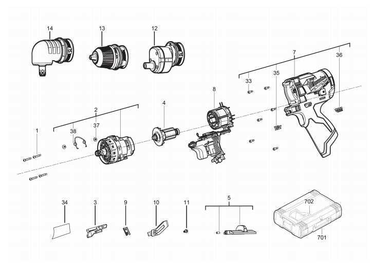
Consider the following enhancements to maximize the efficiency of your equipment:
| Component | Upgrade Option | Benefits |
|---|---|---|
| Cutting Edge | High-speed Steel | Improved durability and cutting speed |
| Motor | Brushless Technology | Increased efficiency and lower maintenance |
| Housing | Aluminum Alloy | Lightweight and corrosion-resistant |
| Control System | Digital Interface | Enhanced precision and ease of use |
Upgrading these critical elements can transform performance, making tasks smoother and more efficient, while also extending the life of your equipment.
Safety Tips for Using Drills
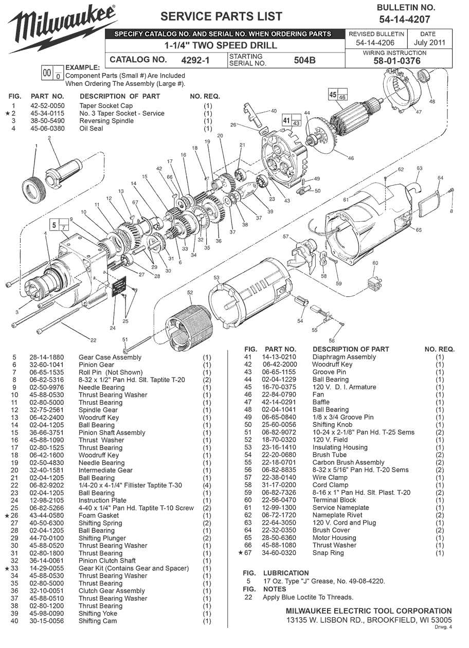
When working with power tools, ensuring safety should be a top priority. Understanding the potential hazards and taking necessary precautions can prevent accidents and injuries, allowing for a more efficient and enjoyable experience. This section outlines essential guidelines to follow when operating these tools, promoting a secure working environment.
Preparation and Protective Gear
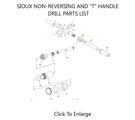
Before starting any project, it is crucial to prepare adequately. Always wear appropriate personal protective equipment, including safety goggles to shield your eyes from debris, ear protection to guard against loud noise, and gloves to protect your hands. Ensure your workspace is well-lit and organized to minimize distractions and hazards.
Proper Usage Techniques
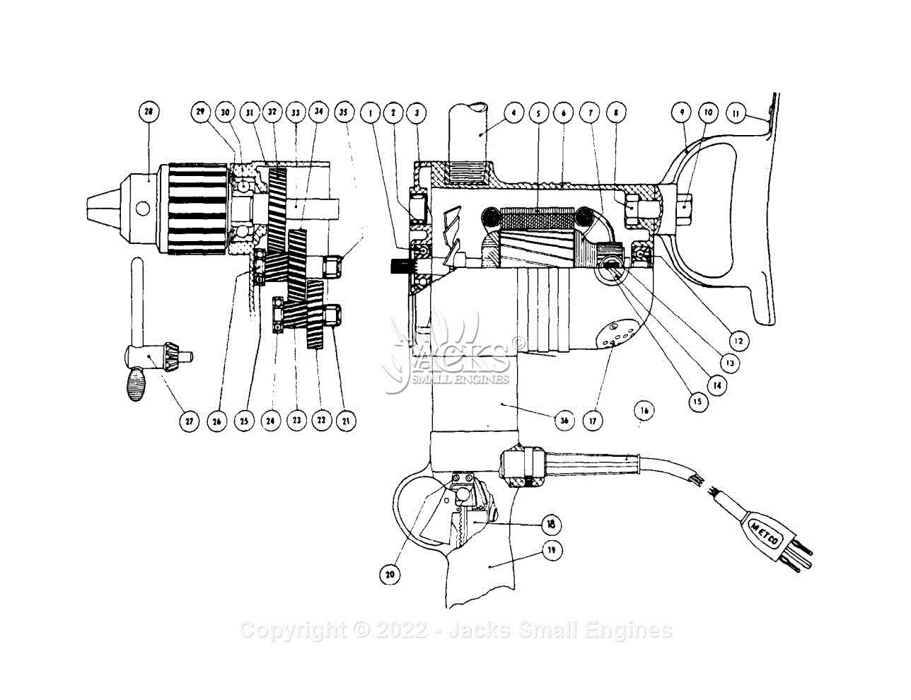
Familiarize yourself with the tool’s functions and controls. Always secure your material before beginning, and maintain a firm grip on the handle. Keep both hands on the tool during operation to maintain control. If you notice any unusual sounds or vibrations, stop immediately to inspect the device. Always disconnect the power source when changing accessories or making adjustments to ensure safety.
By following these tips and remaining vigilant, you can significantly reduce the risk of accidents and ensure a safe working environment.