Internal Parts of a DD15 Engine
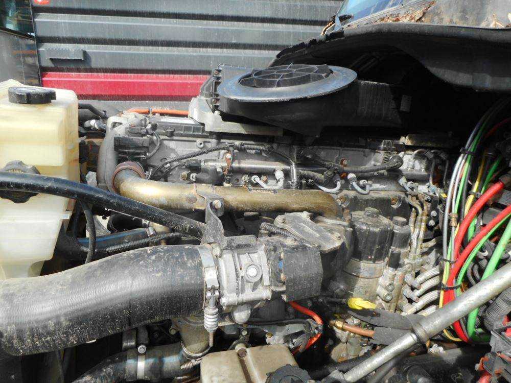
The inner components of this complex machine work together seamlessly to deliver reliable performance. Each element plays a crucial role in ensuring efficient operation, making it essential to understand how these pieces interact. This section will explore key elements that form the core of the system, detailing their functions and importance.
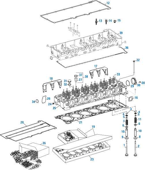
Cylinder Block: Serving as the foundation, the large structure houses the essential chambers where the fuel is combusted, transforming energy into mechanical movement.
Pistons and Connecting Rods: These move in sync, converting the force of combustion into rotational motion, powering the overall system. Their precise alignment is critical for smooth operation.
Crankshaft: A robust piece of the assembly, this rotates to transmit the generated force into usable power. Its durability is key for longevity and consistent output.
Camshaft and Valves: Working in harmony, they regulate the intake and exhaust of gases, ensuring the process runs efficiently. Timing is everything when it comes to this component’s role.
Bearings and Seals: Supporting all moving parts, these provide stability and prevent leakage
DD15 Fuel System Overview
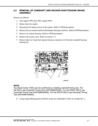
The fuel system is designed to deliver an efficient flow of fuel throughout the vehicle, ensuring optimal performance and combustion. This system integrates several key components that work together to manage fuel delivery and pressure, providing stability and precision in operation.
Key Components
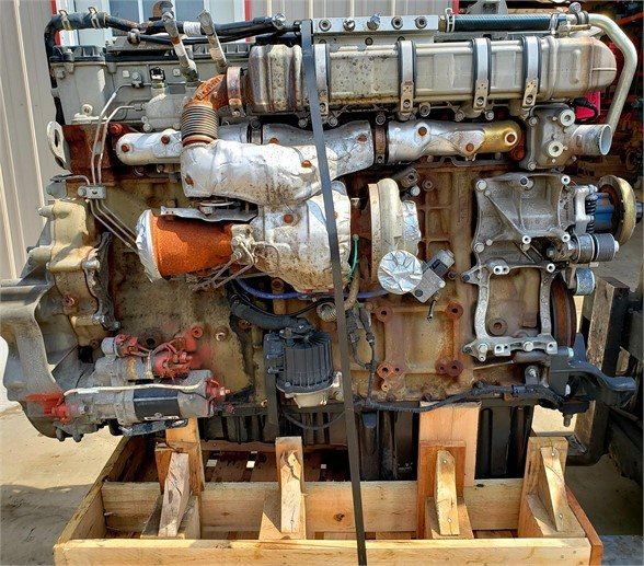
- Fuel injectors
- High-pressure pump
- Fuel rail
- Filters and sensors
How It Works
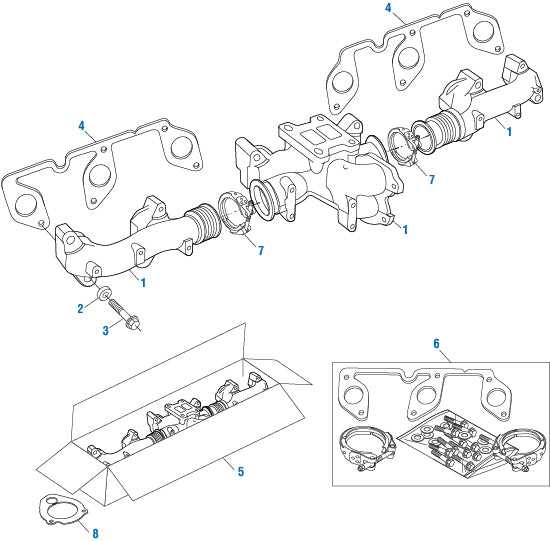
The fuel enters the system through a filtration process, ensuring impurities are removed. Next, the high-pressure pump increases the pressure, allowing fuel to be distributed through the rail and to each injector. Advanced sensors monitor the system, adjusting the pressure and flow as needed to maintain efficiency.
- Fuel filtration begins the process.
- Pressure is boosted by the pump.
- Fuel is delivered to the injectors via the rail.
- Sensors maintain optimal flow and pressure.
Cooling Mechanisms in the DD15 Engine
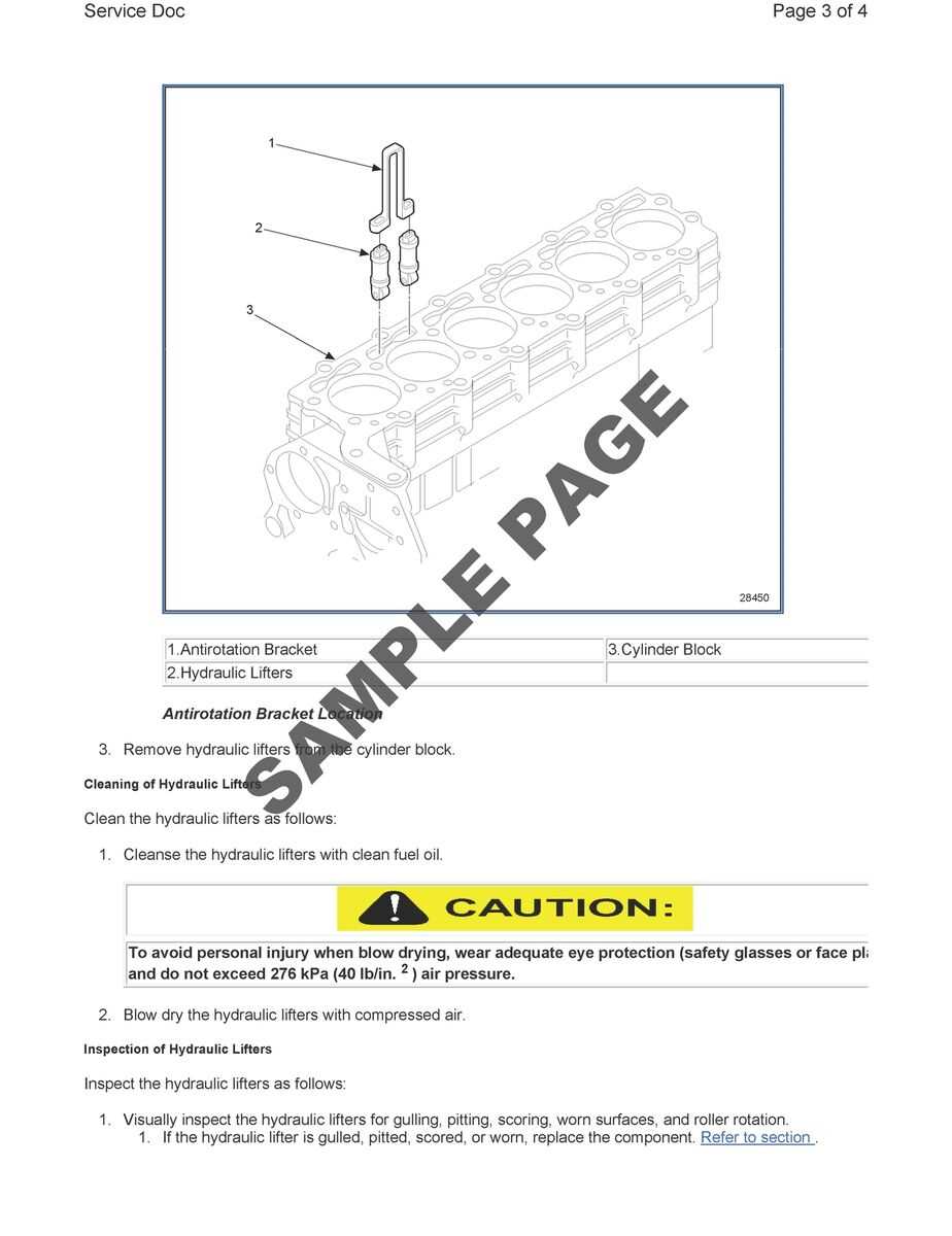
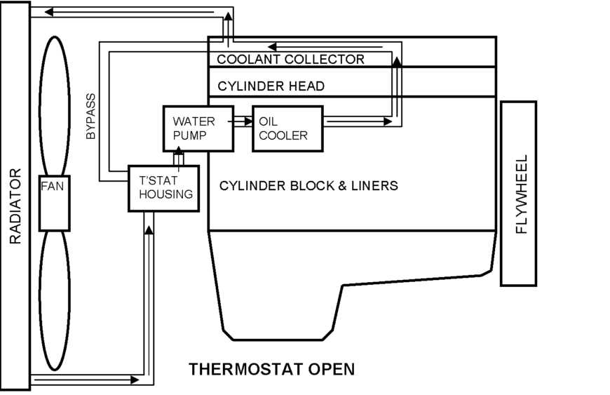
The cooling system in modern machinery is essential for maintaining operational efficiency and preventing overheating. Proper regulation of temperature ensures that all components function smoothly, minimizing wear and tear over time. This system is designed to distribute heat evenly and prevent potential damage from excessive thermal buildup.
Key components in the cooling mechanism work together to circulate fluid and control the internal climate, ensuring the machine operates within safe temperature limits. A network of channels allows for consistent heat dissipation, while specialized materials and fluids enhance the system’s overall performance.
Advanced temperature management methods are employed to maintain optimal functionality. Through a combination of mechanical and chemical solutions, the cooling process ensures a balanced environment, crucial for the longevity and reliability of complex machinery.
Lubrication Pathways in DD15 Engines
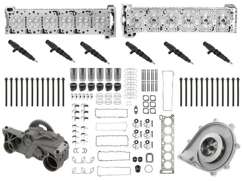
The efficient distribution of lubricant throughout the machinery is crucial for optimal performance and longevity. A well-designed system ensures that every critical component receives the necessary fluid, reducing friction and wear while maintaining operating temperatures. Understanding the flow routes taken by the lubricant reveals insights into the mechanics of reliability and efficiency.
Flow Mechanics
The primary channel directs lubricant from the reservoir to various key areas, promoting a seamless circulation. As the fluid travels, it passes through filters that remove impurities, ensuring that only clean lubricant reaches sensitive components. This process is vital for preventing damage and extending the lifespan of the machinery.
Cooling and Protection
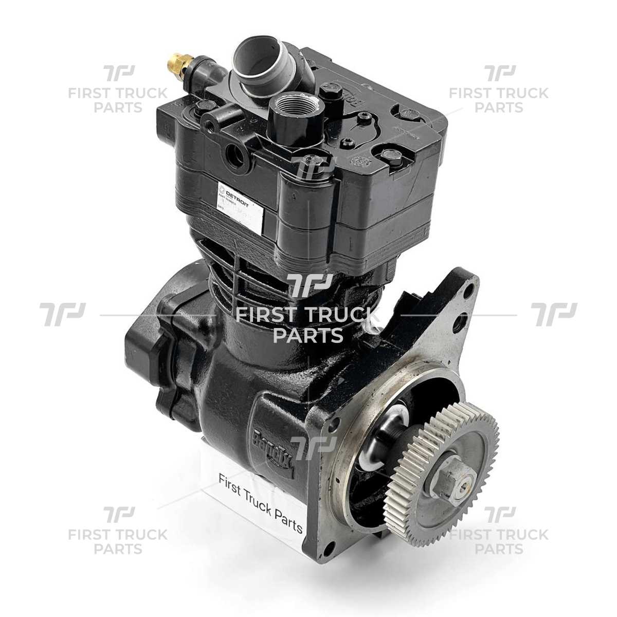
In addition to lubrication, the pathways serve a dual purpose by aiding in cooling. As the lubricant circulates, it absorbs excess heat generated during operation, which is then dissipated through a cooling system. This characteristic not only protects vital components from overheating but also enhances overall efficiency by maintaining optimal operating conditions.
DD15 Engine Exhaust System Breakdown
The exhaust system plays a crucial role in directing gases away from the combustion chamber, ensuring optimal performance and efficiency. This assembly consists of several components that work harmoniously to manage emissions, reduce noise, and improve overall functionality. Understanding the structure and function of these elements is essential for maintenance and troubleshooting.
Key Components of the Exhaust Assembly
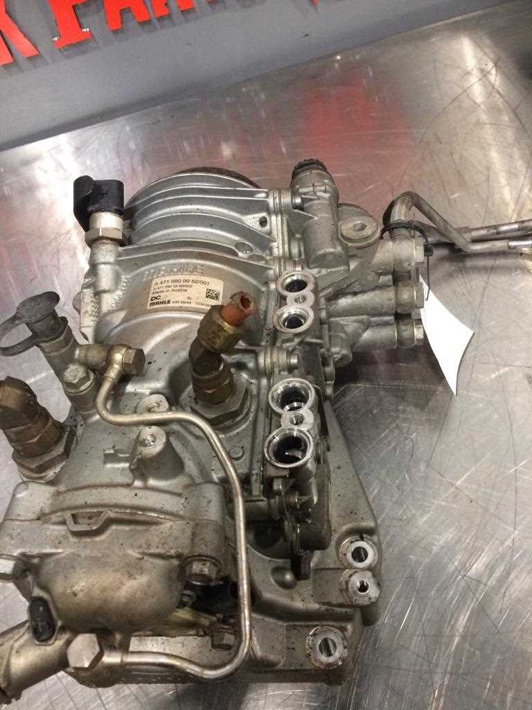
Central to the exhaust assembly is the manifold, which collects gases from the cylinders. Attached to the manifold is the turbocharger, which enhances power output by forcing additional air into the combustion process. Following the turbocharger is the downpipe, responsible for transporting exhaust gases to the next stage of the system.
Emissions Control and Efficiency
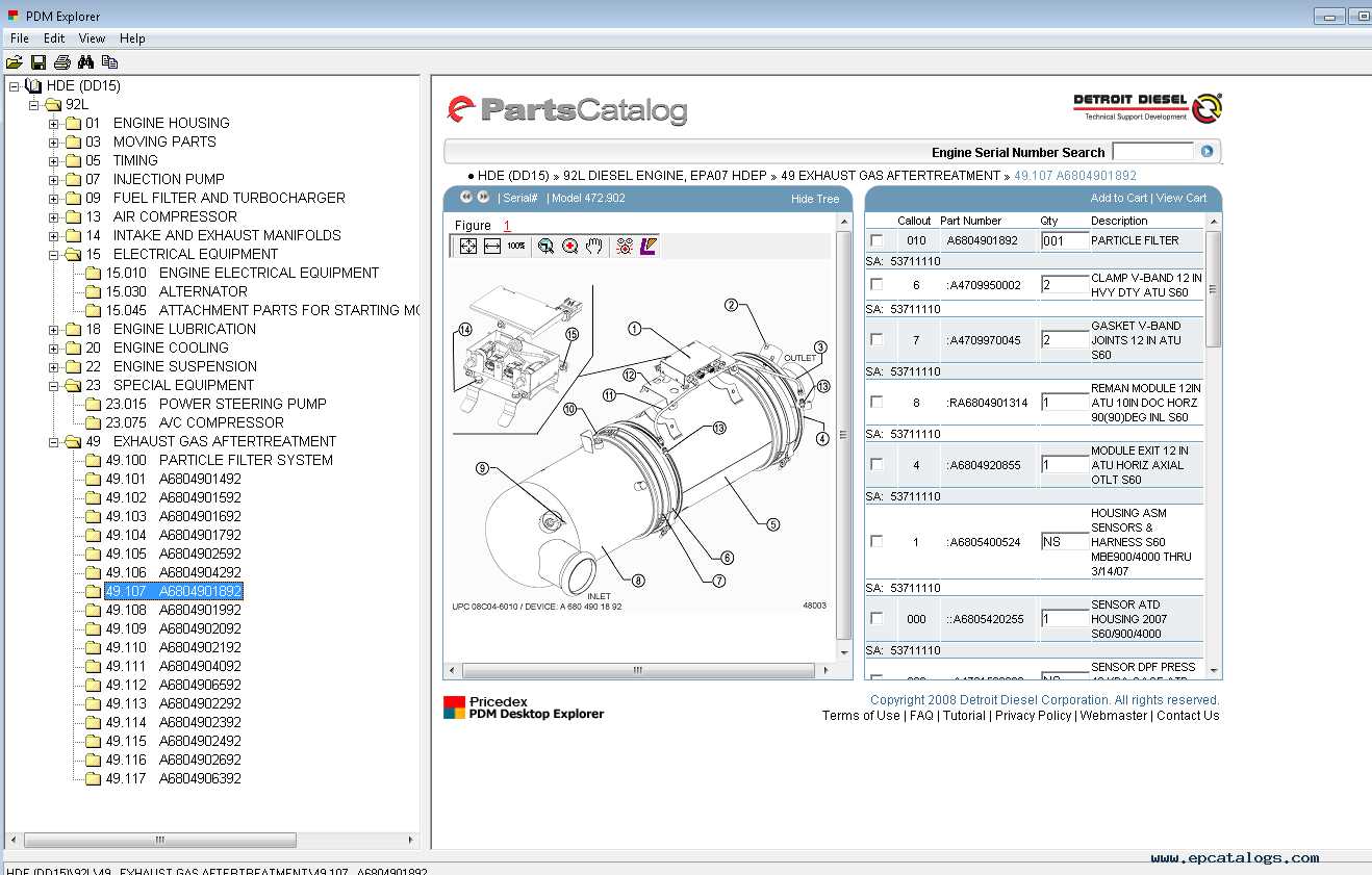
To meet regulatory standards, modern systems are equipped with aftertreatment devices such as catalytic converters and diesel particulate filters. These components significantly reduce harmful emissions, improving environmental compliance. Regular inspection and maintenance of these parts are vital to ensure they function correctly and do not impede the flow of gases, which could lead to performance issues.
Common Wear Areas in DD15 Parts
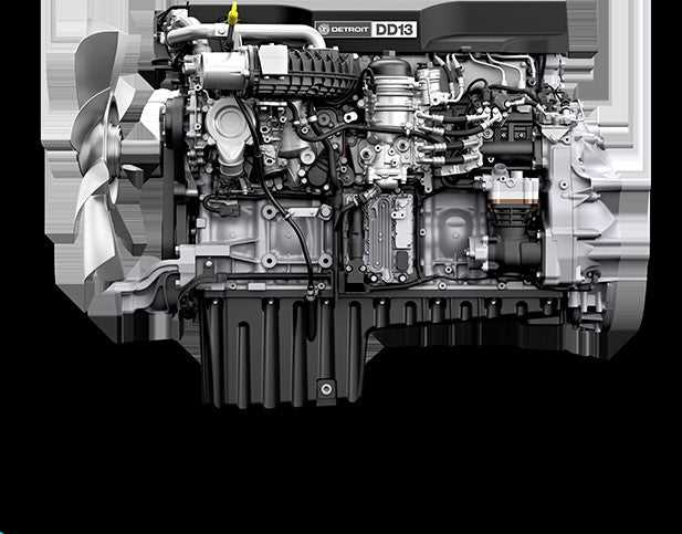
Understanding the typical areas prone to deterioration in heavy-duty machinery is essential for effective maintenance and longevity. Certain components may experience increased stress and wear over time, leading to potential performance issues. Identifying these regions allows for proactive measures, ensuring that machinery operates smoothly and efficiently.
Below is a table highlighting some of the critical locations where wear is often observed, along with their common causes:
| Component Location |
Common Causes of Wear |
| Piston Rings |
Inadequate lubrication, high temperatures |
| Valve Seats |
Excessive heat, poor fuel quality |
| Cylinder Liners |
Contaminated oil, improper installation |
| Crankshaft Bearings |
Overloading, insufficient lubrication |
| Oil Pump |
Debris accumulation, low fluid levels |
Regular inspections and timely replacements of these components can significantly enhance the performance and reliability of the machinery.
|
