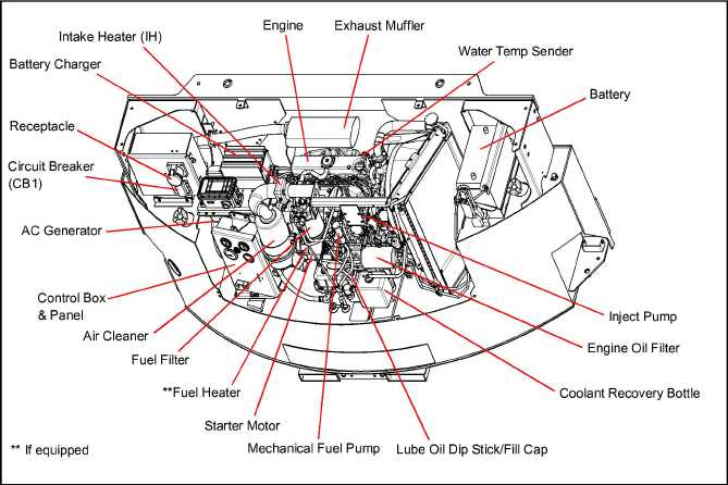
Understanding the internal structure and operation of various mechanical systems is essential for maintaining and troubleshooting them. Each component within these systems plays a critical role in ensuring overall functionality and efficiency. By studying how these elements are interconnected, users can make informed decisions when it comes to repairs and replacements.
Exploring visual representations of system configurations allows for easier identification of individual elements and their relationships to one another. Such a guide can be extremely valuable for technicians and users alike, simplifying the process of disassembling or reassembling the system while avoiding common errors.
In addition, detailed references to specific mechanical elements enable a more precise approach to resolving operational issues. This method ensures that every aspect of the system is addressed, promoting long-term reliability and optimal performance.
Carrier APU Parts Diagram Overview
The illustration provides a comprehensive breakdown of the individual elements and their relationships within the auxiliary power system. Understanding the key components and how they interact is essential for both maintenance and troubleshooting.
Key structural elements within the system include various mechanical and electrical units, which work together to ensure seamless operation. The layout offers a detailed view of each section, enabling users to easily identify and address potential issues.
By familiarizing with this detailed layout, users can efficiently manage repairs, replacements, and optimizations, ensuring the entire system functions smoothly and reliably.
Understanding the Main Components Layout
The layout of key elements in any mechanical system is crucial for ensuring proper functionality and ease of maintenance. By analyzing how various parts are arranged, users can gain a better understanding of the system’s overall design and identify the role of each element. This section will explore the organization of essential components and how their positioning impacts performance.
Core Elements and Their Placement
- Power Source: Positioned centrally to provide consistent energy to the entire system, ensuring balanced distribution of power.
- Cooling Mechanism: Typically located near heat-generating components to regulate temperature and prevent overheating.
- Control Unit: Strategically placed for easy access, enabling users to monitor and adjust system settings efficiently.
Optimizing Component Arrangement
The arrangement of these key elements is designed to maximize efficiency and simplify troubleshooting. A logical layout helps streamline maintenance by ensuring that the most critical elements are easy to reach, reducing downtime during repairs.
- Identify high-wear areas for quick inspection.
- Ensure proper airflow around sensitive components.
- Maintain clear pathways for wiring and connections.
Cooling System and Its Key Elements
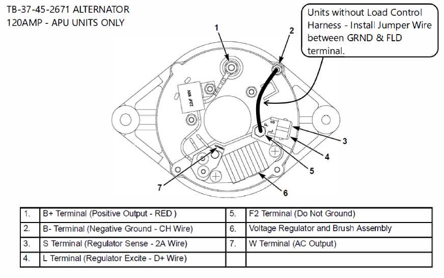
The cooling system is essential for maintaining an optimal temperature by regulating heat exchange. It is responsible for ensuring that the internal components function within safe temperature limits, thus preventing overheating and promoting efficiency. This process involves several important elements that work together to circulate coolant, remove heat, and maintain a stable environment.
Heat Exchanger plays a crucial role in dispersing excess warmth from the system. Through a series of mechanisms, it ensures that heat is efficiently transferred and dissipated.
Coolant Pump is another vital component, driving the fluid circulation that keeps the system cool. Without this steady movement, heat would accumulate, leading to operational issues.
Thermal Sensors monitor temperature levels, ensuring the system reacts in time to any fluctuations. These sensors provide feedback to maintain a balanced environment.
Combined, these elements form a robust framework that prevents overheating, safeguarding the system’s overall performance.
Electrical Connections and Wiring Pathways
Understanding the layout and configuration of electrical connections is crucial for ensuring the proper functioning of any mechanical system. This section provides an overview of the essential wiring routes, highlighting key connection points and ensuring that the flow of electricity is consistent and reliable throughout the entire setup.
- Power Supply Connection: The primary source of electricity is connected through a central unit, which distributes power to all necessary components.
- Grounding Path: Proper grounding ensures safety and reduces the risk of electrical hazards. The system should have a clear and secure path for grounding connections.
- Signal Wiring: Signal wires transmit information between different parts of the system, enabling communication and coordination between components.
- Insulation and Protection: All wiring should be well-insulated to prevent short circuits and damage from environmental factors, ensuring long-term reliability.
Each pathway must be carefully routed to avoid interference or damage, while also adhering to safety standards. Regular inspection of connections is recommended to ensure optimal performance.
Fuel Supply Mechanism Breakdown
The system responsible for delivering fuel ensures a steady and efficient flow from the source to the engine. Its configuration plays a critical role in maintaining consistent performance, allowing the engine to operate smoothly under varying conditions. Each component in the network contributes to the regulation and control of fuel flow.
Key components involved in this process include pumps, filters, and injectors, all working together to optimize fuel delivery. The precision in which the fuel is delivered ensures that the system functions effectively, preventing any interruptions or inefficiencies during operation.
Air Conditioning Parts and Functions
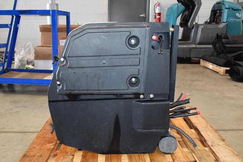
Understanding the components of a cooling system is crucial for ensuring optimal performance and efficiency. Each element plays a vital role in the overall functionality, contributing to the system’s ability to regulate temperature and maintain comfort indoors.
Essential Components
- Compressor: The heart of the system, responsible for circulating refrigerant and compressing gas to increase pressure and temperature.
- Condenser: This unit cools the refrigerant, allowing it to transform from gas to liquid, releasing heat to the outside environment.
- Evaporator: Positioned indoors, it absorbs heat from the indoor air, causing the refrigerant to evaporate and cool the air that circulates through the space.
- Expansion Valve: Regulates the flow of refrigerant into the evaporator, ensuring proper cooling by controlling pressure and temperature.
Supporting Elements
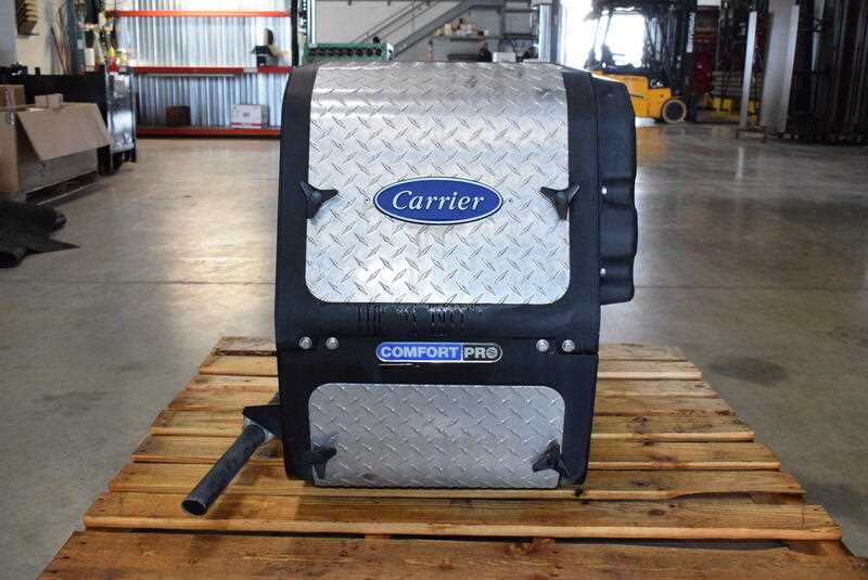
- Blower Fan: Moves air across the evaporator coil, facilitating heat exchange and distributing cool air throughout the area.
- Thermostat: Monitors indoor temperature and adjusts the system’s operation to maintain the desired level of comfort.
- Filters: Capture dust and debris, ensuring that clean air circulates and protecting the internal components from damage.
Maintenance Tips for APU Components
Regular upkeep of auxiliary systems is crucial for ensuring optimal performance and longevity. Adopting a proactive approach to maintenance can prevent costly repairs and enhance efficiency.
- Routine Inspections: Conduct regular checks to identify wear and tear early. Look for signs of leaks, corrosion, or unusual noises.
- Cleanliness: Keep components clean from debris and contaminants. Use appropriate cleaning agents that won’t damage surfaces.
- Fluid Levels: Monitor and maintain proper fluid levels. Regularly check coolant, oil, and fuel to ensure they are within recommended ranges.
- Electrical System Checks: Inspect wiring and connections for corrosion or damage. Ensure all electrical components function correctly to prevent system failures.
- Filter Replacement: Change filters at scheduled intervals to maintain airflow and fluid quality, enhancing system performance.
Implementing these maintenance practices will significantly contribute to the reliability and efficiency of auxiliary systems.
Identifying Common Wear and Tear Areas
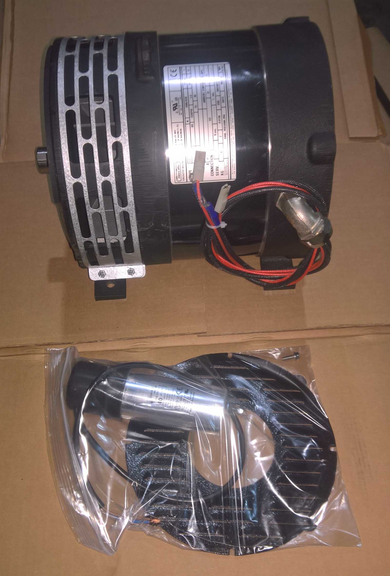
Understanding the typical zones that experience deterioration is crucial for maintaining efficiency and prolonging the lifespan of equipment. Regular inspection and awareness of these regions can help identify potential issues before they escalate, ensuring optimal performance and reducing the likelihood of costly repairs.
Frequent Areas of Concern
Several components are more prone to wear due to constant usage and exposure to varying environmental conditions. These areas often include seals, gaskets, and joints, which may degrade over time, leading to leaks and inefficiencies. Additionally, moving parts such as belts and bearings should be regularly examined for signs of friction and wear, as these can significantly impact functionality.
Signs of Deterioration
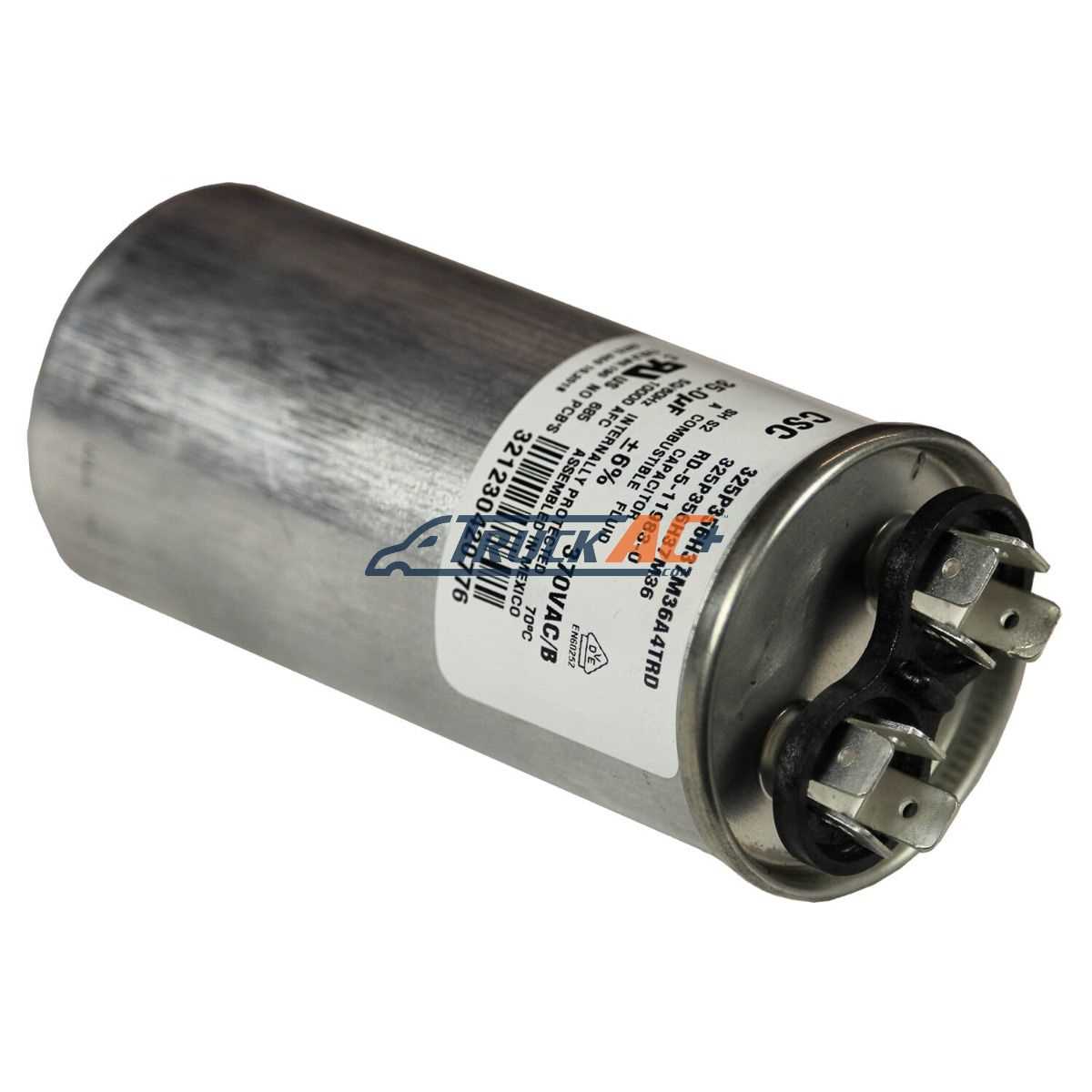
Recognizing early indicators of wear is essential for timely maintenance. Look for unusual noises, leaks, or vibrations, as these can signal underlying issues. Discoloration or cracking in rubber components may also suggest that replacement is necessary. Regular monitoring and addressing these signs promptly can help prevent further damage and ensure the reliable operation of the system.
Best Practices for Efficient Parts Replacement
Replacing components in machinery requires careful consideration and planning to ensure optimal performance and longevity. Adopting effective strategies can streamline the process, reduce downtime, and enhance the overall efficiency of the equipment. Here are several recommendations to achieve successful component substitutions.
| Practice | Description |
|---|---|
| 1. Comprehensive Assessment | Conduct a thorough evaluation of the system to identify the specific components needing replacement, considering factors such as wear, damage, and overall performance. |
| 2. Utilize Quality Components | Always opt for high-quality or OEM alternatives to guarantee compatibility and reliability, thus minimizing future issues and ensuring consistent performance. |
| 3. Follow Manufacturer Guidelines | Adhere to the recommendations provided by the manufacturer regarding installation and maintenance to avoid voiding warranties and ensure proper function. |
| 4. Document Changes | Keep a detailed record of any substitutions made, including dates and reasons for replacement, to maintain a history that aids in future maintenance planning. |
| 5. Regular Maintenance | Implement a routine maintenance schedule to proactively address potential issues and extend the lifespan of both existing and newly replaced components. |