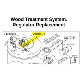
When dealing with complex machinery, it’s crucial to have a clear understanding of its individual elements and how they interact. This section focuses on the essential components that make up the equipment, providing a comprehensive look at their structure and functionality. Proper knowledge of each element plays a vital role in maintaining smooth operations and ensuring efficiency.
By exploring the key sections and assemblies, users can gain valuable insight into the mechanical and functional relationships that make the system work seamlessly. Each part serves a specific role, whether it’s for distribution, control, or protection, and understanding these roles allows for better troubleshooting and optimization of the overall performance.
In this guide, we’ll walk through the main groups that contribute to the effective operation of the device, highlighting their position within the system. This understanding helps users identify potential issues, make informed adjustments, and enhance the longevity of the machine.
Understanding B&G Sprayer Components
When examining the key elements that make up a spraying system, it’s crucial to focus on each individual piece and its role in ensuring smooth and efficient operation. The overall functionality of a device depends on the seamless interaction of various interconnected components, each designed for a specific purpose. Identifying and understanding these elements is essential for both maintenance and effective usage.
Each device is composed of multiple functional units that work together to deliver a reliable performance. Below is a breakdown of the most common components involved in the operation, their roles, and the best practices for their upkeep:
| Component | Description | Role |
|---|---|---|
| Handle | Ergonomically designed for ease of use during operation. | Provides control and stability while dispensing the liquid. |
| Pump | A mechanical or manual system responsible for pressurizing the liquid. | Transfers the liquid through the nozzle with force, enabling efficient coverage. |
| Nozzle | The output component where the liquid exits. | Determines the flow rate and pattern of the output, ensuring precise application. |
| Trigger | The mechanism that activates the flow of the liquid. | Controls the release of the substance, allowing for variable flow depending on pressure. |
| Tank | A container that holds the liquid to be dispensed. | Holds and feeds the liquid to the pump, ensuring continuous flow during operation. |
Key Elements of a Sprayer System
Understanding the core components of a liquid distribution system is crucial for its efficient operation. These systems are designed to ensure precise delivery, reliability, and durability in various applications. Each part plays a significant role in achieving optimal performance, from ensuring even distribution to maintaining the right pressure levels.
The primary elements that make up this type of equipment include:
- Fluid Reservoir: Holds the liquid to be dispensed, ensuring a continuous supply throughout the operation.
- Delivery Mechanism: Facilitates the controlled release of the liquid, often involving pumps or motors that regulate the flow rate.
- Pressure Regulation: Controls the force with which the liquid is expelled, ensuring consistent output and avoiding wastage.
- Application Nozzles: Direct and distribute the liquid in a uniform pattern, optimizing coverage over the target area.
- Hoses and Tubing: Provide the necessary pathways for the liquid to travel from the reservoir to the nozzle.
- Control System: Allows the operator to adjust and monitor the settings, ensuring proper operation and efficiency during use.
Each of these components is designed to work seamlessly together, contributing to the overall effectiveness of the system.
Sprayer Assembly and Function
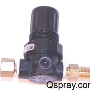
The assembly of a liquid application system involves several interconnected components working together to ensure efficient operation. These systems are designed to distribute liquids precisely and consistently across a targeted area. Each individual piece plays a role in either storage, transport, or application of the solution. The proper functioning of these elements is critical to achieving optimal performance and ensuring that the system operates smoothly under various conditions.
Key Components and Their Role
Several components are integral to the functionality of the application system. Understanding the role of each part helps in maintaining and troubleshooting the setup:
- Reservoir: Holds the liquid to be dispensed, keeping it stable for easy flow.
- Delivery Mechanism: Transfers the liquid from the reservoir to the nozzles or output points.
- Nozzles: Regulate the flow and spray pattern, ensuring even coverage.
- Pressure Control: Ensures the right pressure is maintained for optimal liquid distribution.
- Filters: Prevent blockages and ensure the liquid remains free from contaminants.
System Functionality
The performance of the system relies heavily on how well each of these components works together. Here’s a basic outline of how the system functions:
- The liquid is stored in the reservoir, which is pressurized or gravity-fed to create flow.
- Pressure is adjusted based on the desired spray rate and pattern.
- The liquid travels through hoses or tubes to the nozzles, where it’s dispersed evenly.
- Filters remove any debris to ensure the flow is uninterrupted and consistent.
How the Components Work Together
Understanding the interaction between various elements within a system is crucial for ensuring smooth operation and efficiency. Each element plays a unique role, but it is the coordination between them that brings about optimal performance. When these parts work in harmony, they enhance functionality, minimize errors, and extend the lifespan of the entire mechanism.
Synchronization of Movable Elements
The main moving components are designed to complement each other. Here’s how they interact:
- The central mechanism initiates movement, triggering other elements to respond accordingly.
- Actuators and valves adjust the flow, enabling the desired outcome by controlling the intensity and direction.
- Connecting tubes ensure a consistent transfer of materials, optimizing the efficiency of the system.
Optimizing Efficiency Through Feedback
Feedback mechanisms are essential for continuous improvement and adjustment of performance:
- Sensors monitor the current state and make adjustments to maintain the ideal conditions.
- Pressure gauges track system health, allowing for immediate corrective action when needed.
- Each part responds to changes in real-time, working together to ensure balance and precision.
Common B&G Sprayer Models
Several widely-used devices are designed for the efficient distribution of liquids across various surfaces. These models are valued for their durability, ease of maintenance, and versatility in a variety of tasks. Each model is tailored to specific needs, offering different features and capacities to cater to diverse applications, from industrial to domestic environments.
Understanding the differences between these models can help users select the most suitable one based on their requirements. Below is a list of some of the most popular models and their respective specifications:
| Model | Capacity | Material | Application |
|---|---|---|---|
| Heavy Duty Model | 5 gallons | Stainless Steel | Industrial use, Pest Control |
| Compact Version | 2 gallons | Plastic | Home use, Lawn care |
| Professional Grade | 10 gallons | Aluminum | Agriculture, Commercial applications |
| Portable Model | 1 gallon | Polyethylene | Small-scale tasks, DIY projects |
Overview of Available Variants

This section highlights the different models and configurations available in the market. These variants cater to various needs, from basic setups to advanced systems, providing flexibility and efficiency for users. Each model comes with distinct features and functionalities, designed to suit specific requirements and preferences.
Standard Models
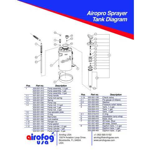
The standard configurations offer essential functions, perfect for users seeking reliable performance without unnecessary complexity. These units are generally more straightforward in design and operation.
- Basic operational features
- Compact design for easy handling
- Cost-effective solution for everyday use
Advanced Models
For those requiring enhanced capabilities, the advanced models provide additional features and more customizable options. These versions are ideal for users who need precision, efficiency, and versatility in their equipment.
- Increased capacity for larger tasks
- Advanced settings for precise control
- Durable components for long-term use
Maintenance Tips for Sprayer Parts
Proper care and routine upkeep of essential equipment components are key to ensuring long-lasting functionality and reliable performance. Regular maintenance helps in preventing wear and tear, reducing the risk of malfunction, and ensuring optimal operation over time. Whether it’s for agricultural tools or any similar device, adhering to a structured maintenance plan is vital.
1. Cleaning and Inspection
- After every use, thoroughly clean all relevant components to remove residue, dirt, and debris.
- Inspect each element for signs of damage, corrosion, or leaks that could affect performance.
- Ensure all moving parts are free of blockages or buildup that may hinder their efficiency.
2. Lubrication and Storage
- Lubricate parts that require smooth motion to reduce friction and prevent premature wear.
- Store the equipment in a dry, cool place away from direct sunlight to prevent material degradation.
- Regularly check seals and joints for any cracks or looseness that might lead to fluid loss or contamination.
How to Keep Your Equipment Efficient
Maintaining optimal performance of your tools requires regular upkeep and attention to detail. Whether it’s a mechanical or electronic system, ensuring that each component is functioning properly is crucial to prolonging the lifespan and achieving consistent results. Proper care can prevent breakdowns, enhance reliability, and reduce the need for costly repairs.
Here are some key practices to consider when managing your equipment:
| Maintenance Task | Frequency | Benefits |
|---|---|---|
| Inspect moving parts | Weekly | Reduces wear and tear, ensures smooth operation |
| Clean regularly | After each use | Prevents buildup of debris and grime |
| Lubricate as needed | Monthly | Reduces friction, extends the lifespan of components |
| Replace damaged parts | As necessary | Prevents further damage and maintains performance |
By adhering to these practices, you can ensure your equipment operates at peak efficiency, minimizing downtime and enhancing overall productivity.
Replacing Damaged Parts in Sprayers
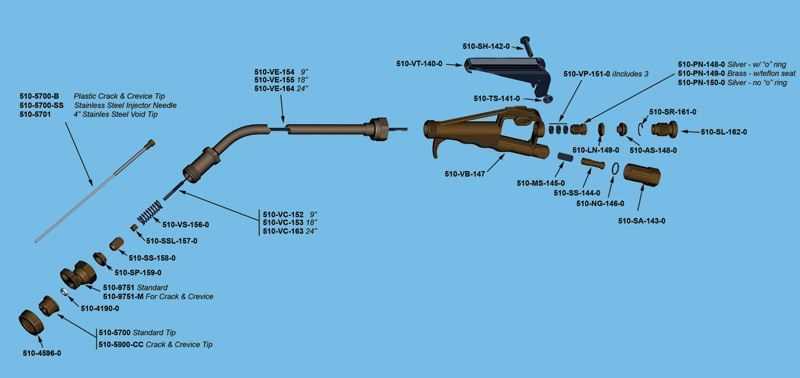
Over time, equipment used for spraying applications may experience wear and tear. Identifying and replacing damaged components is essential for maintaining optimal performance. Proper maintenance ensures that your equipment operates efficiently, preventing downtime and minimizing the risk of malfunction. In this section, we’ll guide you through the process of replacing faulty elements to restore functionality.
Identifying Damaged Components
The first step in the replacement process is to recognize which elements are no longer functioning as intended. Regular inspections help detect issues such as leaks, blockages, or mechanical failures. It is crucial to address these problems promptly to avoid affecting the overall system’s effectiveness.
Steps to Replace Malfunctioning Elements
Once damaged components are identified, follow these general steps to ensure a smooth replacement process:
| Step | Action |
|---|---|
| 1 | Power off the equipment and disconnect from any power source. |
| 2 | Carefully remove the malfunctioning part following the manufacturer’s instructions. |
| 3 | Install the new component, ensuring it fits securely and aligns correctly. |
| 4 | Test the system to verify that the replacement functions as expected. |
When and How to Swap Out Components
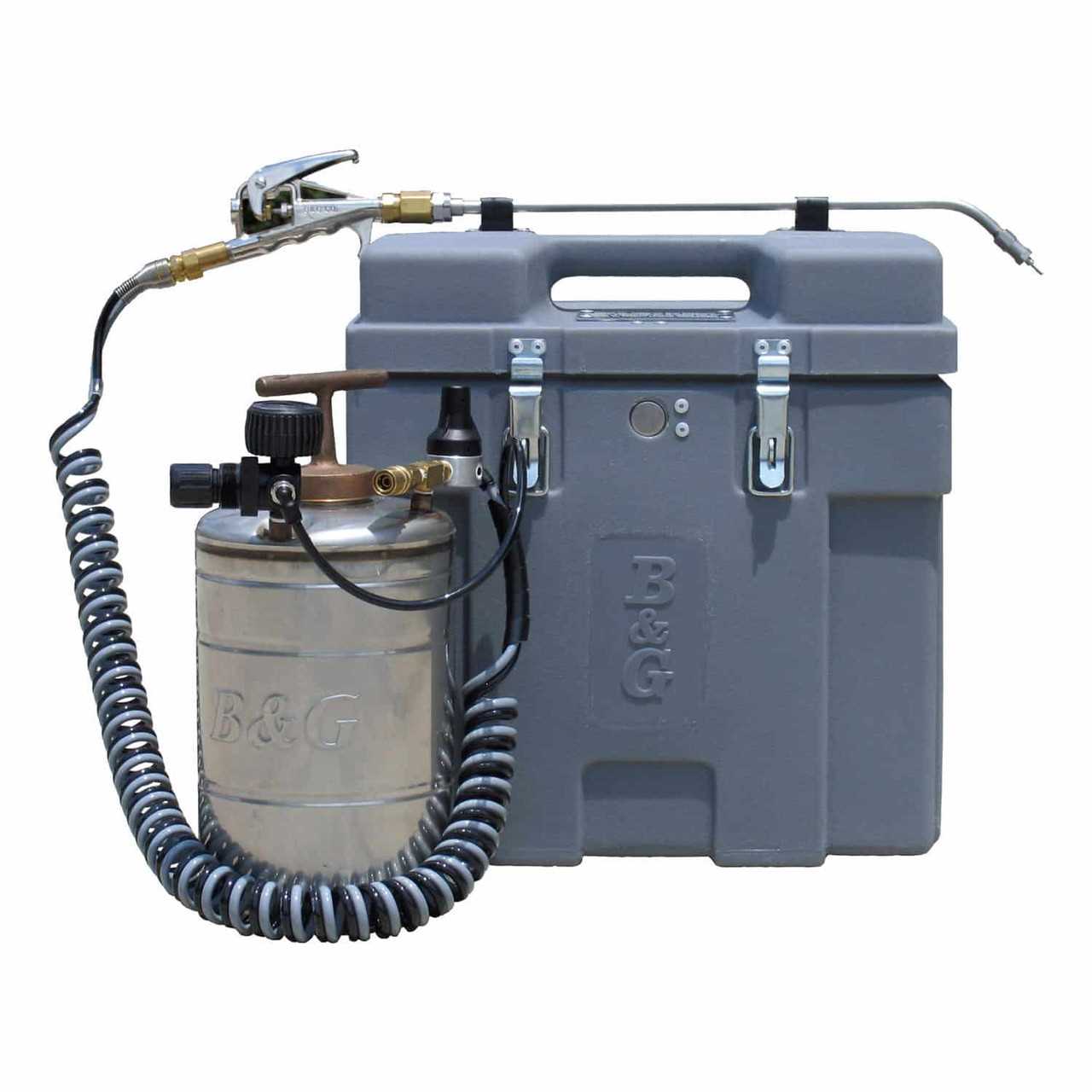
Regular maintenance and timely replacements of certain components are essential to ensuring the optimal functionality of your equipment. Understanding when parts reach the end of their service life is crucial to preventing malfunctions. Replacing worn-out or damaged elements at the right moment can help avoid costly repairs and improve overall performance.
Identifying the Need for Replacement is key to keeping your system in top condition. Most components will show signs of wear through reduced efficiency or visible damage. Monitoring the condition of these elements regularly will help you pinpoint when it’s time for a change.
How to Perform the Swap depends on the specific components involved. Always refer to the manufacturer’s instructions for proper procedures. It is important to handle each part carefully to avoid damaging other systems during the replacement process. If you’re unsure, seeking professional assistance is always a good idea.