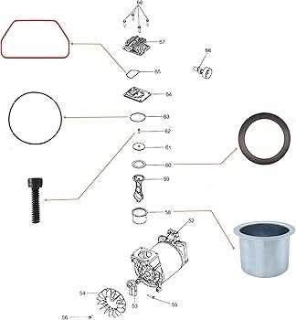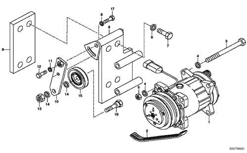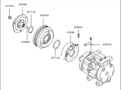
Understanding the intricate arrangement of mechanical elements within a cooling unit provides valuable insight into its operation. These devices rely on a network of interconnected mechanisms that work together to regulate temperatures effectively. By exploring the core components, one can gain a deeper appreciation of how such systems maintain consistent functionality.
A closer examination of the structure reveals individual elements responsible for fluid compression, circulation, and heat exchange. Each section plays a critical role, ensuring efficient energy transfer and smooth operation. Familiarity with these segments helps in troubleshooting and optimizing system performance.
This guide offers a breakdown of essential modules, highlighting their purpose and interaction within the framework. Proper knowledge of these elements not only aids in repairs but also extends the life of the equipment, preventing unnecessary breakdowns and minimizing maintenance costs.
Overview of Compressor Components
Understanding the main elements of a cooling mechanism is essential for efficient system maintenance. These components work together to regulate temperature by managing the flow and transformation of refrigerants within the system.
Motor assembly drives the entire process, powering the mechanism to circulate refrigerants through various stages. Without consistent performance, the system’s efficiency can significantly drop.
An oil reservoir ensures proper lubrication, reducing friction between moving parts. Adequate lubrication not only extends the lifespan of the device but also minimizes operational noise.
Another crucial element is the valve unit, responsible for controlling the flow and pressure. It ensures that refrigerants are directed properly through the system’s stages, preventing unwanted pressure buildup.
Seals and gaskets play an indispensable role in preventing leaks, maintaining stable internal pressure. Even minor damage to these components can lead to significant energy loss and require immediate repair.
How Compressors Power Cooling Systems
Cooling mechanisms rely on the circulation of refrigerants, where pressure changes create the necessary temperature shift. The process begins by compressing vapor, which increases its pressure and temperature, making it easier to transfer heat. This cycle repeats continuously to maintain the desired thermal environment.
Pressure and Temperature Control
The system functions by managing the relationship between low and high-pressure zones. As vapor is compressed, its temperature rises, allowing heat to dissipate when it passes through external coils. The cooled refrigerant then returns to a low-pressure state, ready to absorb more heat from the surroundings.
Continuous Energy Flow
A motorized mechanism ensures the smooth operation of the entire system, driving the refrigerant through the necessary stages. This energy transfer plays a crucial role in maintaining a stable and comfortable atmosphere, ensuring efficient performance over extended periods.
Role of Valves in Airflow Regulation
Valves play a crucial part in managing the movement of gases within mechanical systems. They ensure proper distribution by directing flow paths, balancing pressure, and preventing undesired backflow. Their performance directly impacts the efficiency and longevity of the system.
- Check Valves: Allow flow in one direction while blocking it in the opposite, preventing reverse flow issues.
- Expansion Valves: Control the release of pressurized gases to maintain stable flow levels across components.
- Solenoid Valves: Electrically activated valves that offer precise on-demand regulation of flow.
- Relief Valves: Protect systems by releasing excess pressure, ensuring safety during operation.
Each valve type is essential for maintaining stability and avoiding pressure imbalances, enhancing overall system reliability. Proper valve selection and maintenance are critical to ensure smooth operation and optimal performance under various conditions.
Clutch Mechanism and Its Functionality
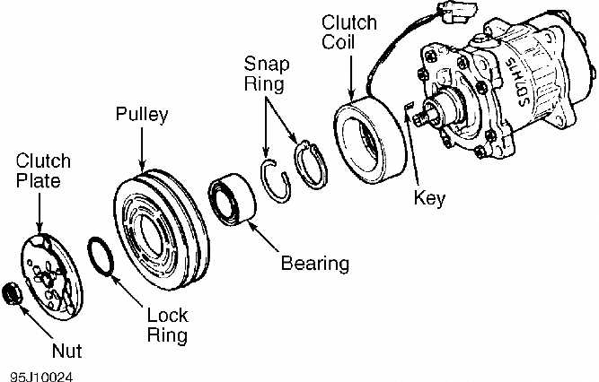
The clutch serves as a key element for regulating the engagement between rotating systems, ensuring efficient control over connected components. It allows selective transmission of motion, activating or disengaging specific elements depending on operational needs.
Mechanically, the clutch links two moving parts, enabling the smooth initiation and cessation of torque transfer. This prevents sudden strain on components and ensures energy is applied precisely when needed. Without it, seamless transitions would be challenging, leading to mechanical wear or malfunction.
Electromagnetic clutches are often employed in modern systems, utilizing electric fields to control the connection. They provide rapid response and high reliability, making them ideal for automated functions. Meanwhile, friction-based designs remain popular in applications requiring robust and straightforward operation.
Importance of Lubrication in Compressors

Proper lubrication plays a crucial role in maintaining the efficiency and longevity of rotating machinery. It minimizes friction between moving elements, reduces wear, and helps manage heat generated during operation. Without effective lubrication, performance drops, and mechanical failures become more likely.
- Friction reduction: A well-lubricated system ensures smoother interaction between surfaces, preventing unnecessary energy loss.
- Temperature control: Lubricants dissipate heat generated by friction, avoiding overheating and ensuring continuous function.
- Wear prevention: By forming a protective film, lubrication reduces metal-to-metal contact, minimizing abrasion and extending service life.
- Corrosion resistance: Many lubricants contain additives that protect internal surfaces from moisture and chemical exposure.
- Sealant function: In some designs, lubricants also serve as a seal, preventing leaks and ensuring pressure stability.
Choosing the right type and quantity of lubrication is essential. Overuse or underuse can lead to issues, such as excessive build-up or insufficient protection. Regular inspection and timely replacement of lubricants are key practices to avoid breakdowns and maintain optimal function.
Common Signs of Compressor Failure
Mechanical cooling systems rely on core components to maintain functionality. When one of these essential mechanisms starts to falter, it can disrupt the entire operation, causing a noticeable impact on performance and energy efficiency.
Unusual Noises or Vibrations
One of the earliest indicators is the presence of unexpected sounds, such as rattling, clunking, or loud humming. These noises suggest that internal components are misaligned, worn out, or experiencing excessive friction, which can lead to further mechanical damage.
Reduced Cooling Capacity
A system that struggles to maintain the desired temperature may signal internal faults. This reduction in cooling efficiency often points to pressure imbalances, mechanical wear, or insufficient lubrication within the key functional elements. If left unresolved, it can lead to complete failure.
Frequent On/Off Cycling: Rapid cycling is another warning sign. When the system switches on and off more frequently than normal, it can indicate a malfunction in pressure regulation, heat transfer, or motor operation, increasing the strain on components and accelerating breakdown.
Increased Energy Consumption: An unexplained rise in power usage often accompanies mechanical issues. Faulty internal components force the system to work harder, consuming more electricity to maintain the desired output, which can be costly in the long run.
Pressure Sensors and Their Operation
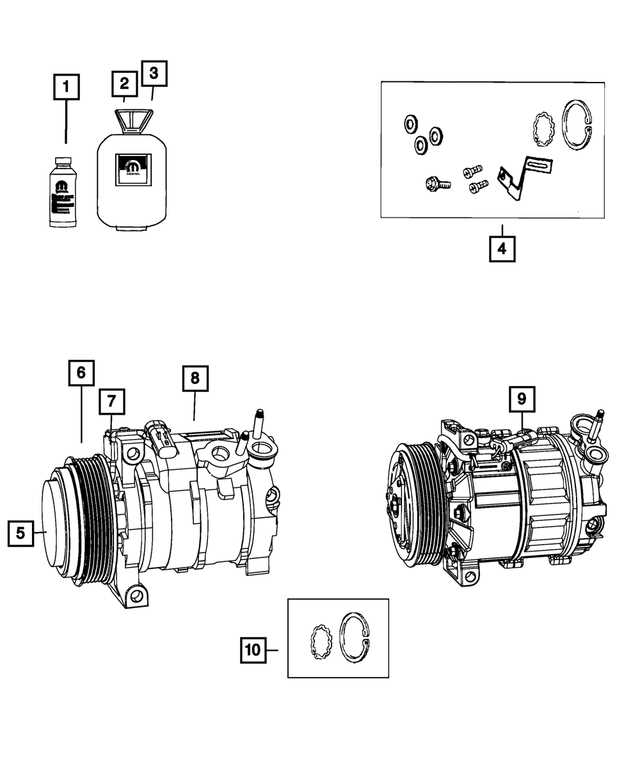
Pressure sensors play a crucial role in monitoring and regulating fluid systems. They provide feedback by detecting changes in force applied to liquids or gases, ensuring efficient operation across various applications. These sensors convert pressure variations into electrical signals, which can then be processed by control units to maintain stability.
Types of Pressure Sensors
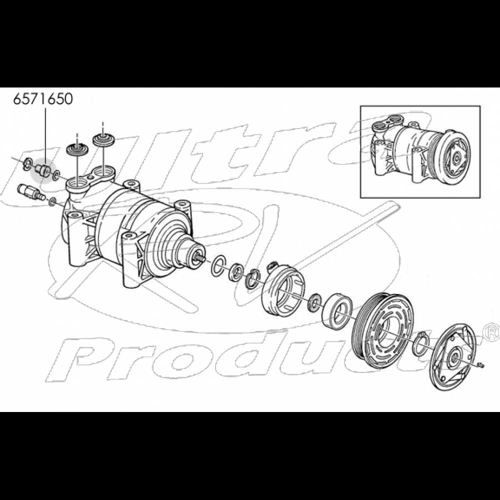
Different sensor types are used based on specific requirements. Some measure absolute pressure, while others focus on gauge or differential readings. Each type offers unique benefits, whether for precision control, overload protection, or system safety.
| Sensor Type | Measurement Approach | Use Case | ||||||||
|---|---|---|---|---|---|---|---|---|---|---|
| Absolute Sensor | Measures relative to a vacuum reference | Used in scientific experiments | ||||||||
| Gauge Sensor | Compares pressure to ambient conditions | Common in automotive systems | ||||||||
| Differential Sensor |
| Component | Function |
|---|---|
| Terminals | Connect wires to the unit, allowing power transfer. |
| Relays | Control the flow of electricity based on operational needs. |
| Wiring Harness | Bundles and organizes electrical connections for efficiency. |
| Fuses | Protect the system from overloads and short circuits. |
Proper installation and regular checks of these electrical components are vital to maintaining functionality and preventing issues that could arise from wear or damage. A comprehensive understanding of these connections allows for better troubleshooting and enhances the longevity of the unit.
