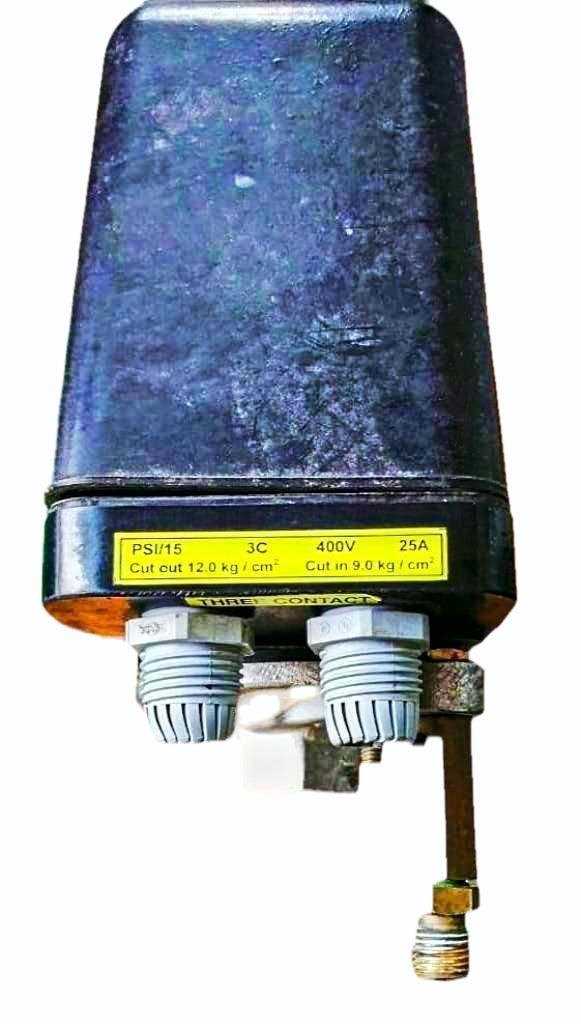
In various industrial and domestic applications, the efficient regulation of system operations relies on specific mechanisms designed to monitor and manage performance levels. These systems play a crucial role in ensuring optimal functionality, enhancing reliability, and prolonging the lifespan of equipment. A clear grasp of the individual components involved is essential for effective troubleshooting and maintenance.
Each element within these regulating systems has a distinct role, contributing to the overall effectiveness of the mechanism. Familiarity with how these elements interact and function together is vital for anyone involved in equipment maintenance or system design. This knowledge not only aids in identifying potential issues but also enhances the ability to implement effective solutions.
In the following sections, we will delve into the intricacies of these essential components, exploring their functions and how they collectively support the overall operation. By examining the arrangement and relationship between these elements, we can gain valuable insights into the efficient management of mechanical systems.
Understanding the Pressure Switch Components
In this section, we will explore the essential elements that contribute to the functionality of a control mechanism. Each component plays a critical role in ensuring the effective operation and regulation of the system, providing stability and reliability.
Key components include various sensors, contacts, and adjustment mechanisms, all of which work together to facilitate the correct performance of the system. A thorough understanding of these elements allows for better troubleshooting and maintenance practices.
| Component | Description |
|---|---|
| Sensor | Detects variations in the system’s condition and provides feedback for adjustments. |
| Contacts | Electromechanical devices that open or close circuits, allowing or interrupting the flow of electricity. |
| Adjustment Mechanism | Enables users to calibrate the operation according to specific requirements, enhancing flexibility. |
| Housing | Protects internal components from external factors, ensuring durability and longevity. |
Functionality of Each Part
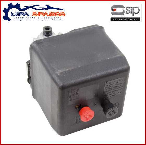
This section explores the roles of various components within a control mechanism, highlighting how each element contributes to the overall operation. Understanding these functions is essential for effective maintenance and troubleshooting.
Key Components Overview
The following table summarizes the main elements and their specific functions within the control system:
| Component | Function |
|---|---|
| Actuator | Responsible for initiating actions based on received signals, regulating the system’s performance. |
| Sensor | Monitors relevant parameters, providing real-time feedback to ensure optimal operation. |
| Control Module | Processes input data and determines the appropriate actions, serving as the brain of the system. |
| Relay | Acts as a switch to control larger loads, enhancing safety and efficiency in operations. |
Operational Interactions
Each component interacts seamlessly, ensuring the system functions as intended. The actuator responds to the sensor’s readings, while the control module processes this data to activate the relay. This interconnectedness is crucial for maintaining the desired performance levels.
Common Types of Pressure Switches
In various applications, controlling fluid dynamics is crucial for efficient operation. Different devices are utilized to monitor and regulate the levels of force within systems. Understanding the distinct categories of these monitoring devices can aid in selecting the right one for specific needs.
1. Mechanical Devices
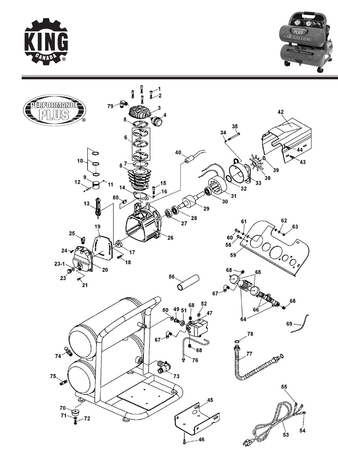
Mechanical devices operate based on the movement of a diaphragm or piston. When the force exceeds a predetermined threshold, the mechanism activates a response. These are commonly used in applications requiring straightforward functionality.
- Diaphragm Mechanisms: These devices use a flexible membrane to sense changes in force.
- Piston Mechanisms: Employing a piston, these units provide robust performance under high-force conditions.
2. Electronic Devices
Electronic devices leverage sensors and electronic components to provide precise monitoring and control. These systems often include programmable features for customized operation, making them suitable for advanced applications.
- Digital Sensors: These units offer real-time readings and can be integrated into automated systems.
- Smart Devices: Equipped with connectivity features, these monitors allow for remote management and data logging.
Identifying Pressure Switch Failures
Recognizing the signs of malfunctioning components in your system is crucial for maintaining optimal functionality. Various symptoms may indicate that specific elements are not operating correctly, which can lead to inefficiencies or complete system failure. Understanding these indicators can assist in early diagnosis and prevent more significant issues down the line.
Common indicators of failure include unusual noises, irregular cycling, and failure to maintain desired levels. These signs can stem from various sources, often pointing to specific components that require inspection or replacement. Proper troubleshooting involves examining each element systematically to identify the root cause of the issue.
| Indicator | Possible Cause | Recommended Action |
|---|---|---|
| Unusual noises | Worn components or debris | Inspect and clean or replace affected parts |
| Irregular cycling | Faulty sensors or incorrect settings | Check settings and replace malfunctioning sensors |
| Failure to maintain levels | Leaks or blockage in the system | Inspect for leaks or obstructions and repair |
Regular maintenance and attention to these signs can greatly extend the life of your system and improve overall efficiency. If persistent issues arise, consulting a professional may be necessary to ensure comprehensive evaluation and repair.
Wiring Diagrams for Connections
Understanding the layout of electrical connections is crucial for ensuring proper functionality and safety. This section provides a comprehensive overview of various configurations that facilitate effective linkages in a system. By utilizing accurate schematics, users can achieve seamless integration of components.
Key Components in Wiring Layouts
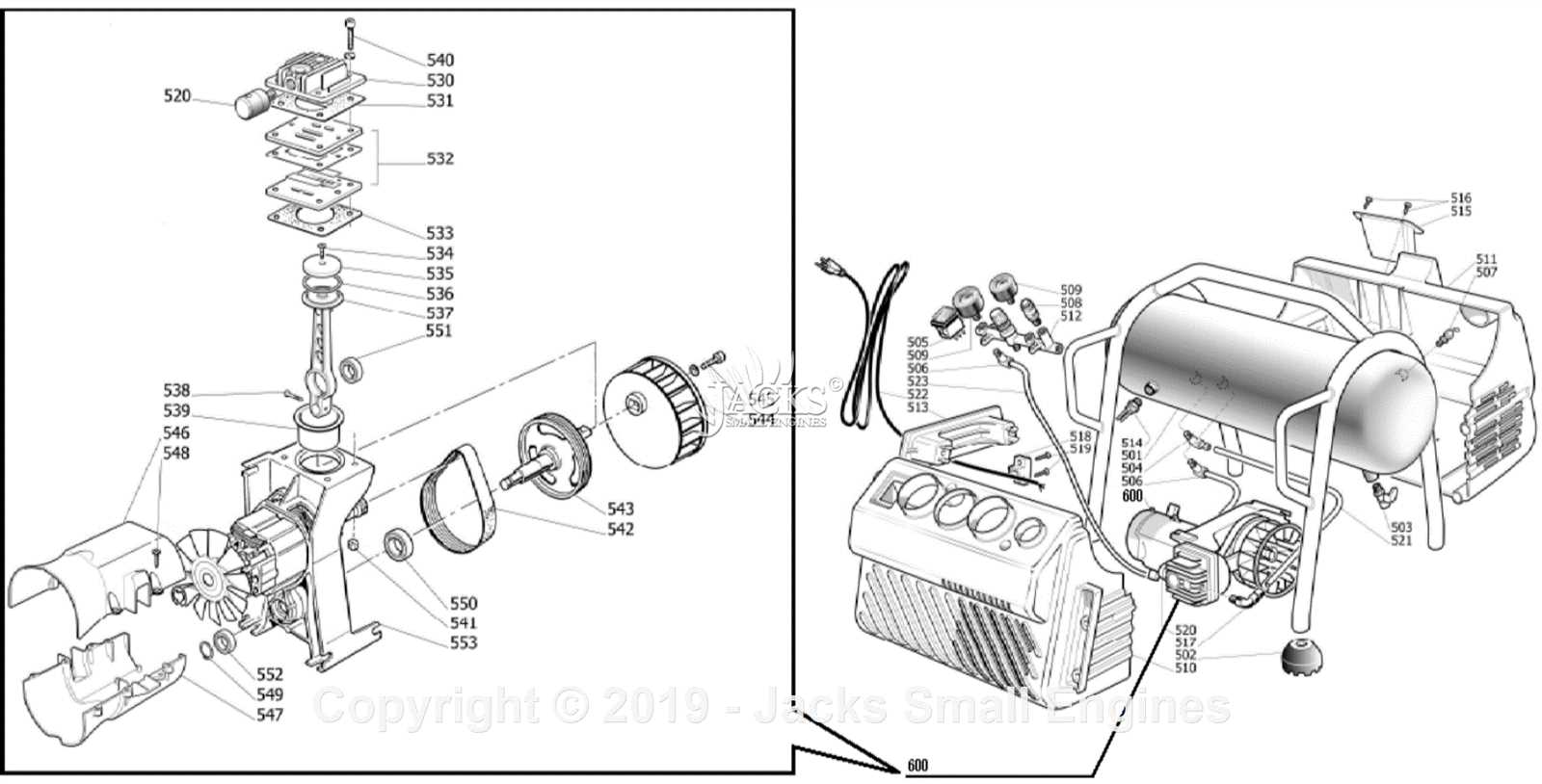
- Power Supply: The source that provides energy to the system.
- Control Elements: Devices that manage and regulate the operation.
- Connecting Wires: Conductors that link different elements together.
- Safety Features: Components that protect against overloads and malfunctions.
Common Wiring Arrangements
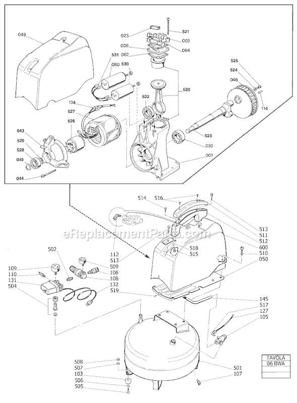
- Series Configuration: All elements are connected along a single path.
- Parallel Configuration: Components are linked across common points, allowing for multiple pathways.
- Complex Layout: A combination of series and parallel arrangements to optimize performance.
By familiarizing oneself with these fundamental concepts, users can ensure reliable connections and enhance the overall efficiency of their systems.
Maintenance Tips for Longevity
Ensuring the durability of your equipment requires regular attention and care. Implementing a few simple practices can significantly enhance the lifespan and performance of your machinery. By adhering to these maintenance suggestions, you can avoid common issues and ensure optimal functionality.
| Maintenance Activity | Frequency | Description |
|---|---|---|
| Inspect Seals | Monthly | Check all seals for wear and tear to prevent leaks and maintain efficiency. |
| Clean Filters | Bi-Monthly | Remove and clean filters to enhance airflow and performance. |
| Lubricate Moving Parts | Quarterly | Apply appropriate lubricants to ensure smooth operation and reduce friction. |
| Check Connections | Monthly | Inspect all electrical and mechanical connections for stability and integrity. |
| Monitor Performance | Ongoing | Regularly assess the operational performance to identify any anomalies. |
By following these guidelines, you can maintain the efficiency and reliability of your equipment, ultimately leading to enhanced performance and reduced downtime.
Replacement Parts and Options
When it comes to maintaining and upgrading your equipment, understanding the available alternatives for essential components is crucial. This section highlights various replacement items that ensure optimal functionality and performance. Selecting the right options can enhance efficiency and extend the lifespan of your system.
Types of Alternatives
- Seals and Gaskets: These components prevent leaks and maintain internal pressure, ensuring the system operates smoothly.
- Relief Valves: Essential for regulating excess pressure, these devices protect the machinery from potential damage.
- Control Modules: Upgrading to advanced control units can improve responsiveness and functionality.
- Electrical Connectors: Reliable connectors are vital for ensuring proper power transmission and safety.
Choosing Quality Options
When selecting replacement components, consider the following factors:
- Compatibility: Ensure the items match the specifications of your existing equipment.
- Material Quality: Opt for durable materials that can withstand the operational demands.
- Supplier Reputation: Purchase from trusted manufacturers to guarantee reliability and performance.
- Warranty: Check for warranties or guarantees to safeguard your investment.
Installing a New Pressure Switch
Replacing an essential component in your system can significantly enhance its functionality and efficiency. This section provides a comprehensive guide on the steps involved in integrating a new device designed to regulate and control operational levels.
Preparation is Key: Before beginning the installation process, ensure you have all necessary tools and components readily available. This will streamline the procedure and minimize the risk of interruptions. Safety gear should also be on hand to protect against potential hazards.
Disconnecting the System: Prior to any work, it is crucial to disconnect the unit from its power source. This step is vital to avoid electrical shocks or accidents during installation. Once disconnected, relieve any residual pressure within the system to ensure a safe working environment.
Removing the Old Component: Locate the existing device and carefully detach it from its mounting position. Take note of the wiring configuration and connections, as this information will be beneficial when connecting the new unit. If necessary, document the setup with photographs for reference.
Installing the New Device: Position the new component in the same location as the previous one. Secure it firmly to prevent any movement during operation. Reconnect the wiring according to the previously noted configuration, ensuring all connections are tight and secure.
Final Checks: Once the installation is complete, reattach the power source and perform a thorough inspection. Activate the system and monitor its performance to ensure the new device functions correctly and efficiently. If any issues arise, revisit the installation steps to verify that everything is properly set up.