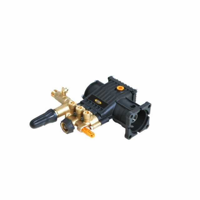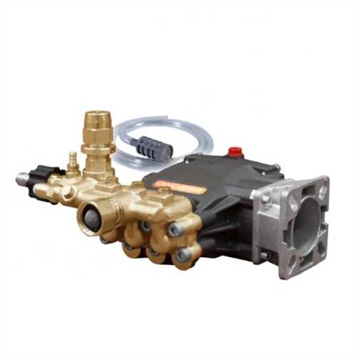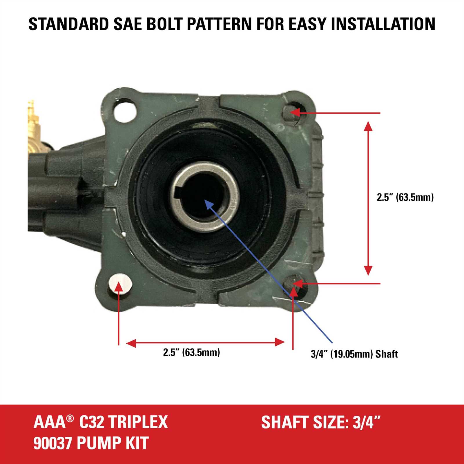
In the realm of fluid dynamics, comprehending the intricate assembly of components is vital for ensuring optimal functionality. This section delves into the various elements that contribute to the efficiency and performance of these systems. By exploring the relationships and configurations of each part, one gains insight into how they work together seamlessly.
The detailed examination of these crucial elements reveals their individual roles and significance. From the core mechanisms that drive the movement of liquids to the auxiliary features that enhance operational stability, each component is designed with precision. This understanding not only aids in troubleshooting but also empowers users to maintain and optimize their systems effectively.
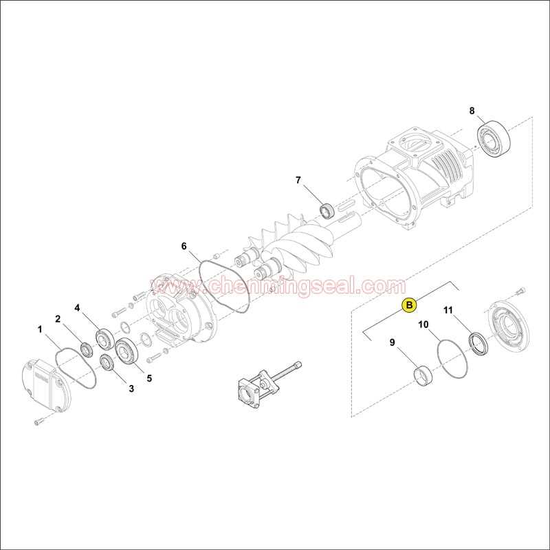
Moreover, visual representations of these elements serve as invaluable tools for both novices and experts alike. By illustrating the layout and interconnections, these graphics simplify complex concepts, making them accessible for deeper learning. Through this exploration, readers will gain a comprehensive view of how each segment contributes to the overall efficiency and reliability of hydraulic operations.
Understanding 8.7ga12 Pump Functionality

This section explores the intricate workings of a specific fluid transfer device, highlighting its operational principles and components. By examining how each element interacts, we can gain insight into the overall effectiveness of the system.
The core mechanism involves converting mechanical energy into fluid motion, allowing for efficient transportation of various substances. Essential components work in harmony, creating a cycle that enhances performance and reliability.
Maintenance plays a crucial role in ensuring longevity and optimal functioning. Regular checks on critical elements can prevent malfunctions, thereby sustaining operational efficiency over time.
Ultimately, understanding the functionality of this system not only aids in effective troubleshooting but also enhances user confidence in its application.
Key Components of the Pump Assembly
The effectiveness of any fluid transfer system relies heavily on its essential elements. Each component plays a pivotal role in ensuring optimal functionality and longevity. Understanding these integral parts is crucial for maintenance and troubleshooting.
Main Elements
- Housing: This outer structure provides protection and support for internal components.
- Impeller: A rotating element that imparts energy to the fluid, facilitating movement.
- Seal: This component prevents leaks and ensures that the system remains pressurized.
- Motor: The driving force that powers the impeller and initiates fluid movement.
Supporting Components
- Volute: This spiral-shaped casing helps in directing the flow of fluid efficiently.
- Bearing: Reduces friction between moving parts, enhancing overall performance.
- Strainer: Filters out debris and contaminants to protect internal components.
- Discharge Pipe: Transports the fluid away from the assembly to its destination.
Recognizing and understanding these key elements aids in efficient operation and maintenance, ultimately extending the lifespan of the system.
How to Read Pump Diagrams
Understanding visual representations of machinery components is crucial for effective maintenance and troubleshooting. These illustrations serve as guides, providing a clear depiction of the assembly, flow paths, and relationships between different elements. By familiarizing oneself with the symbols and layouts used, one can efficiently navigate the complexities of mechanical systems.
To begin, it’s essential to identify the various symbols that represent specific elements, such as valves, inlets, and outlets. Each symbol usually has a standardized meaning, allowing users to interpret the functionality and arrangement quickly. Additionally, directional arrows are often employed to indicate the flow of fluid, making it easier to grasp how the system operates.
Next, pay attention to the legend or key typically provided alongside the visual. This section elucidates the meanings of the symbols, ensuring clarity in interpretation. Understanding these conventions can drastically reduce confusion and enhance the ability to analyze the system’s layout.
Lastly, always consider the context in which the representation is used. Different industries may adopt unique styles or terminologies, so being adaptable and open to learning can prove invaluable. With practice, reading these illustrations becomes an intuitive process, ultimately leading to better performance in system management.
Common Issues with Pump Parts
In the realm of mechanical systems, certain challenges frequently arise, impacting functionality and efficiency. Understanding these obstacles can aid in better maintenance and longevity of the components involved.
Frequent Problems
- Wear and Tear: Regular usage leads to degradation of materials.
- Corrosion: Exposure to various environments can compromise integrity.
- Blockages: Debris accumulation can hinder performance.
- Misalignment: Improper installation may result in operational issues.
Troubleshooting Tips
- Inspect components regularly for signs of damage.
- Clean areas prone to debris accumulation.
- Ensure proper alignment during installation.
- Use protective coatings to combat corrosion.
Maintenance Tips for Longevity
Ensuring the durability and efficiency of mechanical devices requires regular upkeep and attention. By implementing a few simple practices, you can significantly extend their operational life and optimize performance.
1. Regular Inspections: Conduct frequent checks to identify any signs of wear or damage early. This proactive approach helps prevent more significant issues down the line.
2. Cleanliness: Maintain a clean environment around the equipment. Dirt and debris can lead to premature failure, so regular cleaning is essential.
3. Lubrication: Apply appropriate lubricants to moving components as specified by the manufacturer. Proper lubrication reduces friction and minimizes wear.
4. Monitor Performance: Keep an eye on performance metrics. Any deviations from normal functioning can indicate underlying problems that need addressing.
5. Follow Manufacturer Guidelines: Adhere to the maintenance schedule and recommendations provided by the manufacturer. This ensures that all necessary actions are taken at the right intervals.
By integrating these maintenance strategies into your routine, you can achieve the ultimate longevity and reliability of your equipment.
Identifying Replacement Parts Quickly
Efficiently locating necessary components is crucial for maintaining optimal performance. Familiarity with the structure and functionality of each element can significantly enhance the replacement process. By understanding the specific characteristics and variations, you can streamline your search and minimize downtime.
Utilizing detailed schematics can aid in visualizing the assembly, allowing for quicker identification of required items. Consider organizing components by category or function, which can facilitate easy access and reduce confusion during the selection process.
Additionally, keeping an inventory of frequently replaced elements ensures you are prepared for any unforeseen issues. Regularly updating your knowledge about new alternatives or improvements in design can also lead to more efficient maintenance and enhanced system reliability.
Benefits of Accurate Diagrams
Precise illustrations serve as invaluable tools in various fields, enhancing understanding and communication. By providing clear representations, they enable users to grasp complex systems and components effortlessly.
Enhanced Understanding
- Simplifies intricate concepts.
- Facilitates quick learning.
- Reduces misinterpretation.
Improved Efficiency

- Streamlines troubleshooting processes.
- Guides maintenance activities.
- Boosts productivity through clarity.
Differences Between Similar Pump Models
When evaluating various models in a specific machinery category, it’s crucial to understand how they diverge in functionality, efficiency, and design. These distinctions can significantly influence performance, maintenance, and overall suitability for particular applications. Analyzing these factors helps in making informed decisions for both industrial and commercial uses.
| Feature | Model A | Model B |
|---|---|---|
| Flow Rate | 150 L/min | 120 L/min |
| Pressure Range | 1-10 bar | 0.5-8 bar |
| Efficiency | 85% | 80% |
| Weight | 50 kg | 45 kg |
| Noise Level | 70 dB | 65 dB |
Understanding these variations allows users to select the most appropriate model based on specific operational requirements and constraints. By considering factors such as output capacity, durability, and sound emissions, one can optimize performance while adhering to budgetary and environmental standards.
Where to Find Reliable Resources
Accessing trustworthy information is crucial for effective troubleshooting and maintenance. Various platforms and publications can provide accurate insights, enabling users to enhance their understanding and ensure optimal functionality.
Online Databases and Forums
Numerous websites host extensive databases and community forums where enthusiasts and professionals share their knowledge. Engaging with these platforms allows users to connect with experienced individuals and access valuable documentation.
Manufacturer’s Documentation

Directly consulting official documentation from manufacturers guarantees the most precise and relevant information. Manuals, guides, and technical specifications are often available on their websites, serving as essential resources for reliable data.