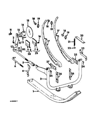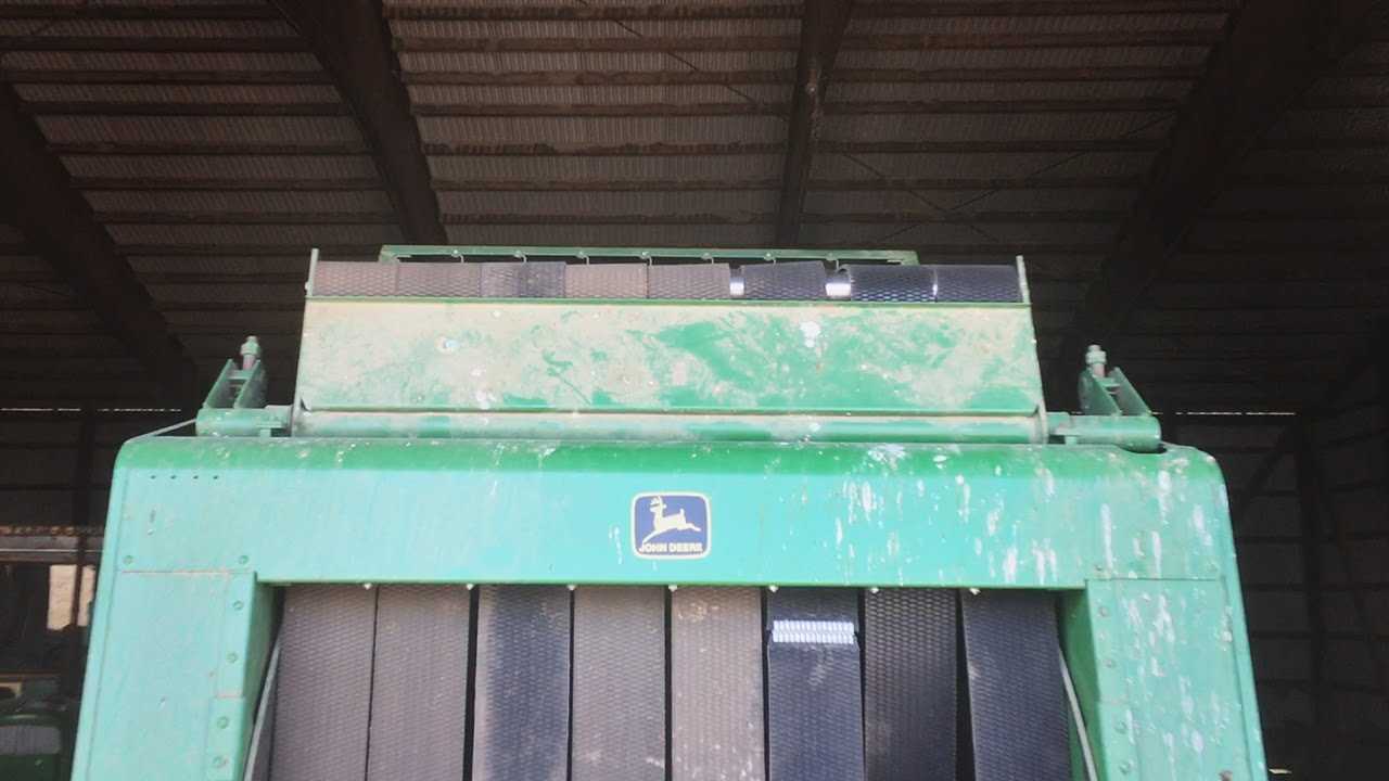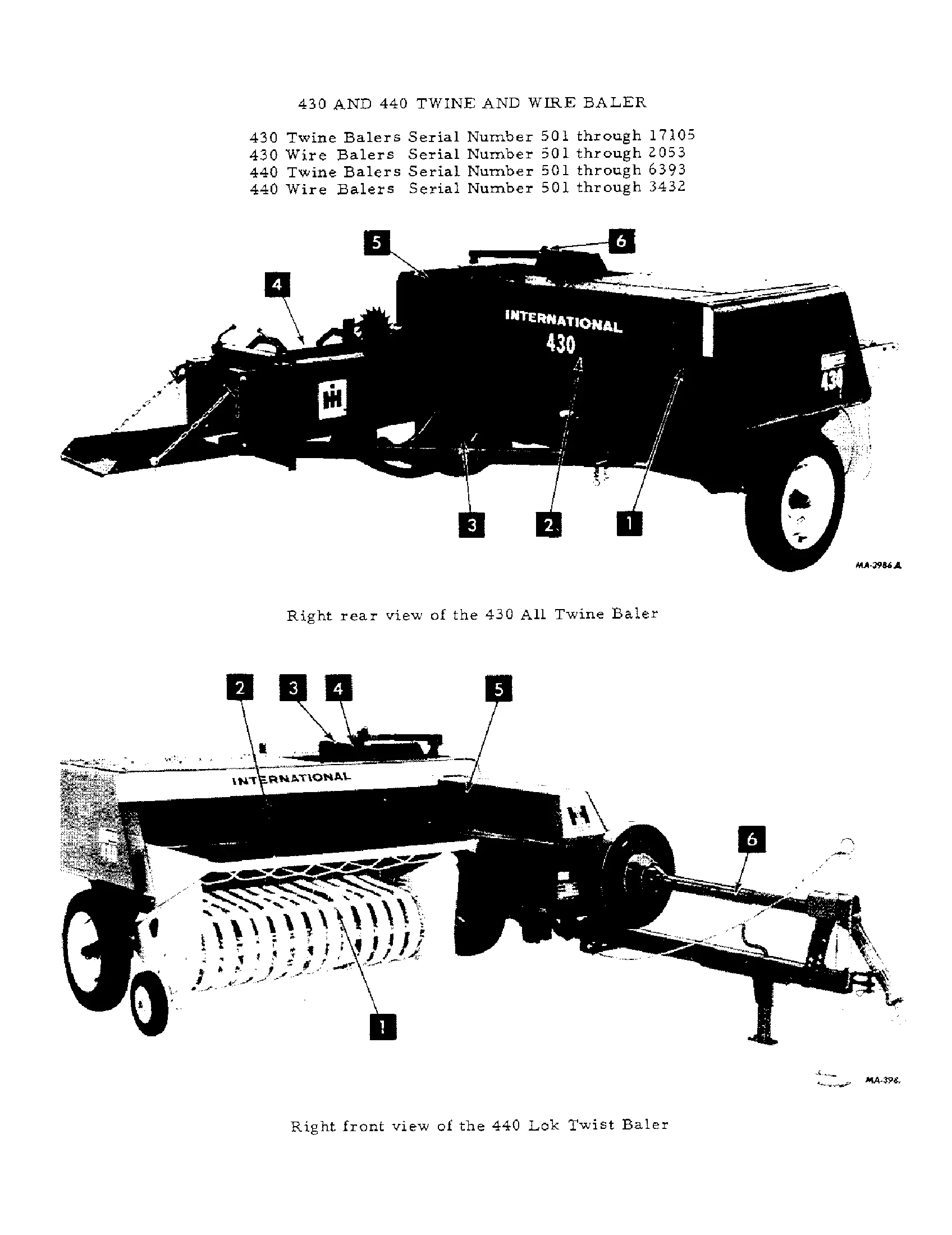
Agricultural machinery plays a crucial role in modern farming, providing efficiency and precision in various tasks. Understanding the individual elements of such equipment is essential for maintenance and troubleshooting. By breaking down the machinery into its core components, we can gain a deeper insight into its functionality.
Each piece of farming equipment consists of multiple working parts that interact to deliver the expected performance. Whether you’re looking to repair or simply comprehend how these machines work, a detailed overview of their mechanical structure will guide you through the process of identifying and understanding each element.
In this section, we will explore the various mechanical parts and how they fit together to create an efficient tool for harvesting and processing. Knowing the functions of these components can help in identifying potential issues and ensure that everything works smoothly during operation.
Overview of Key Components
This section provides a detailed look at the essential mechanisms found in modern agricultural equipment used for processing and handling materials. Each component plays a crucial role in ensuring the smooth operation and efficiency of the machine. By understanding the function of these elements, operators can ensure proper maintenance and avoid potential issues.
| Component | Function |
|---|---|
| Pickup | Responsible for collecting the material from the ground and directing it into the machine for further processing. |
| Feeding System | Moves the collected material into the chamber where it is compressed and shaped. |
| Compression Chamber | Compacts the material to form a denser package, ready for tying or wrapping. |
| Tying Mechanism | Ensures the tightly packed material is securely bound, preventing it from unraveling during transport or storage. |
| Discharge Gate | Releases the finished product onto the ground or into a transport vehicle for further handling. |
Main Functions of the Baler
The primary role of this machinery is to compact and form crops into dense, manageable units. By gathering loose materials, it facilitates their storage and transport, ensuring that harvested produce is efficiently handled. These devices simplify agricultural processes by minimizing the space taken up by the crops, making them more practical for both short-term handling and long-term storage.
Compression Mechanism: One of the essential functions is the mechanism that compresses the material, creating a tightly packed structure. This function ensures that the maximum amount of crop is condensed into a manageable form, reducing the need for frequent stops during the collection process.
Wrapping and Binding: Another key function is the automatic wrapping or binding of the compacted material, securing it for easy handling. This step is vital for maintaining the shape and integrity of the unit, preventing it from falling apart during transport or storage.
Understanding the Knotter Mechanism
The knotter mechanism plays a crucial role in ensuring secure binding during the baling process. By tying the material efficiently, it allows for smooth operation and consistent bale formation. A properly functioning knotter is essential for avoiding issues that can disrupt productivity.
Main Components of the Knotter
The knotter mechanism consists of several key elements that work together to tie and secure the material. These include the twine holder, the needle, and the bill hook. Each part has a specific role, contributing to the overall performance of the system. Regular maintenance and proper adjustment of these components are necessary to ensure reliable operation.
Common Issues and Troubleshooting

Sometimes, the knotter may encounter problems such as missed knots or uneven tying. These issues can often be traced back to incorrect adjustments or wear and tear on specific parts. Ensuring that the tension settings are accurate and regularly inspecting the components for damage can prevent most of these problems and ensure smooth functioning.
Details on the Pickup Assembly
The pickup assembly is a crucial component that ensures effective gathering of materials from the ground, feeding them into the machine for further processing. It is designed to handle various conditions and material types, making it an essential part of the overall efficiency and performance.
Main Components of the Pickup System
- Pickup tines – responsible for lifting the material from the ground and guiding it into the machine.
- Reel – works to control the flow of the material, ensuring it moves smoothly through the assembly.
- Cam track – manages the movement and timing of the tines to ensure proper material pickup.
Maintenance Tips for Optimal Function
- Regularly inspect the tines for wear and damage, replacing them as necessary.
- Ensure the reel and cam track are properly lubricated to maintain smooth operation.
- Check for any obstructions or debris that may interfere with the performance of the assembly.
Explaining the Tensioner System
The tensioner system is designed to maintain the proper force on various components during operation. This mechanism ensures consistent performance by adjusting the tension automatically as needed, avoiding potential disruptions.
Main Components of the Tensioner
Key elements of the system include pulleys, springs, and belts. These parts work in unison to keep the tension balanced, allowing for smooth and efficient function throughout different tasks. The spring mechanism plays a critical role, as it adjusts tension according to the demands placed on the machinery.
How the Tensioner Works
The tensioner automatically regulates the pressure based on real-time conditions. When the force on the system changes, the spring-loaded components react immediately, maintaining optimum tension to ensure continuous operation. This reduces the need for manual adjustments and enhances the overall reliability.
Maintenance of the Drive Chain
Proper upkeep of the drive mechanism is crucial for ensuring optimal performance and longevity of agricultural machinery. Regular inspections and timely interventions can prevent wear and tear, reducing the likelihood of unexpected breakdowns and costly repairs.
Inspection Procedures

Regular checks should be conducted to assess the condition of the drive chain. Look for signs of wear, such as elongation or rust. Ensure that the chain is properly tensioned and aligned with the sprockets. This will help maintain efficiency and reduce the risk of slippage or breakage.
Lubrication and Cleaning
Keeping the drive chain lubricated is essential for smooth operation. Use an appropriate lubricant to minimize friction and protect against corrosion. Additionally, clean the chain regularly to remove dirt and debris that can impede its function.
| Maintenance Task | Frequency | Notes |
|---|---|---|
| Visual Inspection | Weekly | Check for wear and alignment |
| Lubrication | Monthly | Use recommended lubricant |
| Cleaning | Every 3 Months | Remove dirt and debris |
Hydraulic System Parts Breakdown
The hydraulic system is a vital component that facilitates the efficient operation of agricultural machinery. Understanding the various elements involved in this system is crucial for maintenance and troubleshooting. Each part plays a specific role in ensuring smooth hydraulic function, contributing to the overall effectiveness of the equipment.
Main Components of the Hydraulic System
This section highlights the essential elements that make up the hydraulic mechanism. Key components include pumps, valves, cylinders, and hoses, each designed to work in harmony. The pump generates the necessary pressure, while valves control the flow, ensuring that the hydraulic fluid is directed to where it is needed most.
Each component within the hydraulic system serves a unique purpose, contributing to the overall functionality. For instance, cylinders convert hydraulic energy into mechanical force, while hoses transport the fluid, facilitating movement throughout the system. Understanding these functions is vital for efficient operation and effective maintenance practices.
How to Replace Belts
Replacing the belts on agricultural equipment is essential for ensuring optimal performance and preventing mechanical failures. Proper maintenance can extend the life of the machinery and improve its efficiency. This section outlines the steps to effectively change the belts, ensuring safety and accuracy throughout the process.
Before starting, make sure to gather all necessary tools and replacement components. It is advisable to consult the specific equipment manual for precise instructions tailored to your machine’s model. Below is a table summarizing the essential tools and materials needed for this task:
| Tool/Material | Description |
|---|---|
| Wrenches | Used for loosening and tightening bolts. |
| Screwdrivers | Required for removing covers or securing parts. |
| Replacement Belts | Ensure you have the correct size and type. |
| Safety Gear | Protective gloves and goggles are recommended. |
Start by disconnecting the power source to avoid accidents. Remove any guards or covers that obstruct access to the belts. Carefully document the current routing of the belts or take pictures for reference. Once you have access, remove the old belts by loosening the tension and sliding them off the pulleys. Install the new belts following the documented routing, ensuring they sit correctly in the pulleys.
After installation, check the tension on the new belts and adjust as needed to ensure proper operation. Finally, replace any covers or guards and reconnect the power source. Always perform a test run to confirm that everything operates smoothly before resuming regular use.