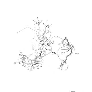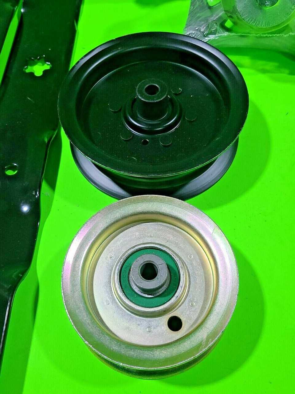
Understanding the internal structure and various elements of mechanical systems is essential for efficient maintenance and troubleshooting. By familiarizing yourself with the layout and connections of each element, it becomes easier to identify potential issues and ensure smooth operation.
In this section, we’ll explore the intricate layout of a widely-used machine, delving into its essential elements and how they interconnect. With this comprehensive guide, you’ll gain valuable insights into the most critical components, helping to maintain optimal performance and avoid unexpected breakdowns.
Key mechanical elements will be outlined to enhance your understanding, ensuring that each part is recognized and its function is clear. This will aid in both routine maintenance and more complex repairs, allowing for greater efficiency and precision.
Essential Components Overview
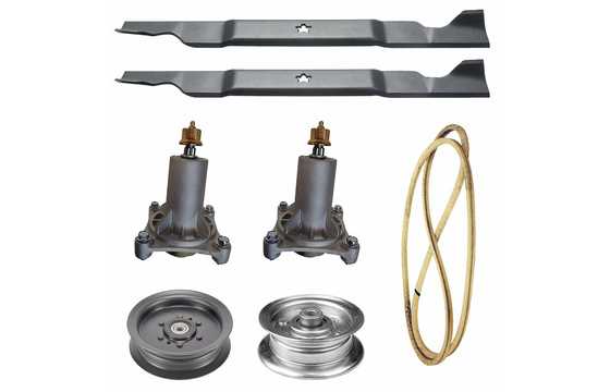
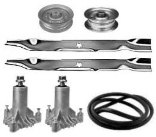
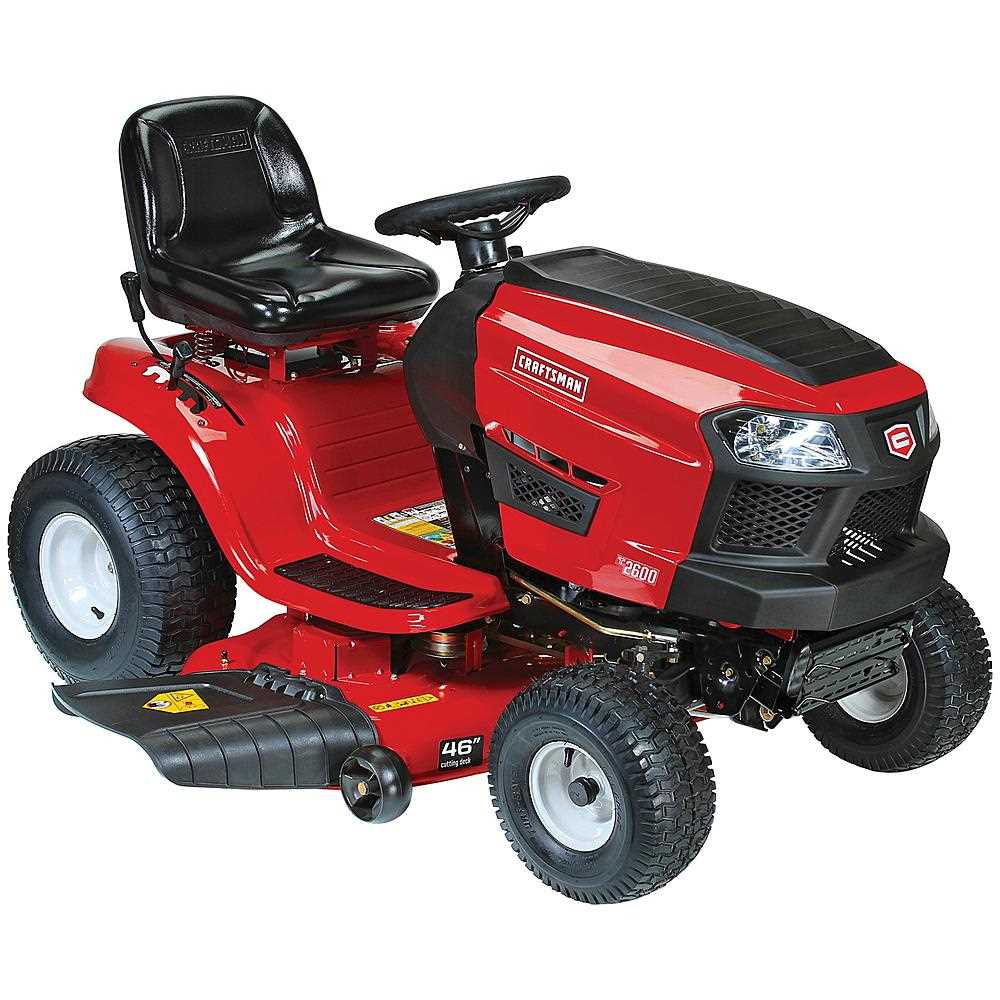
This section provides an in-depth look at the primary mechanical elements that form the backbone of this robust garden tractor. These components are integral to its operation, ensuring efficiency, durability, and ease of maintenance. Understanding the function of each element is crucial for optimal performance and long-term reliability.
Key Structural Elements
The frame and support system provide the foundation, offering strength and stability. The steering mechanism and wheels contribute to maneuverability, making it easier to navigate various terrains.
Operational Mechanisms
The power unit drives the entire machine, while the transmission system ensures smooth motion. Coupled with a durable cutting deck, these elements work together to deliver consistent results.
| Component | Function |
|---|---|
| Frame | Provides structural support and stability. |
| Steering System | Ensures smooth control and direction.
Engine Structure and Key Elements
The internal structure of the engine is designed to ensure efficient performance and durability. Understanding the various components that make up the engine can help in maintaining its optimal functionality and recognizing potential issues before they become major problems. Main Components of the Engine
Supporting Systems
Each of these components works in unison to guarantee the smooth operation of the e Transmission System BreakdownThe transmission system is essential for the efficient operation of any riding equipment, ensuring smooth power delivery from the engine to the wheels. This section focuses on the various components involved in the system, how they function together, and what to look for during maintenance or repairs. Main Components of the TransmissionThe transmission assembly consists of several key elements, including gears, belts, and linkages, each playing a vital role in controlling the movement and speed of the machine. Proper synchronization of these components is necessary for optimal performance. Common Issues and SolutionsOver time, wear and tear can lead to common issues such as slipping belts or gear misalignment. Regular inspections and timely adjustments can prevent these problems from affecting overall functionality, ensuring a long lifespan for the transmission system. Understanding the Steering MechanismThe steering system plays a critical role in ensuring smooth control and navigation of the vehicle. By converting the rotation of the steering wheel into the movement of the wheels, it provides the driver with precise handling. A clear understanding of how these components work together can help in identifying issues and maintaining optimal performance. Key Components of the Steering System
How It All Works Together
Front and Rear Wheel AssembliesThe wheel assemblies play a crucial role in the overall performance and stability of the equipment. These components are designed to ensure smooth movement and effective handling, contributing to the efficiency of the machine. Understanding their structure and functionality is essential for maintaining optimal operation. The front wheel assembly typically consists of the wheel, axle, and hub, all of which work together to provide directional control and support. This assembly is engineered to withstand various loads and ensure stability during operation. In contrast, the rear wheel assembly is designed to support the weight of the machine while providing traction and support on different surfaces. Its construction is vital for enhancing performance and durability. Electrical Components and Wiring LayoutThe efficiency of any power tool relies heavily on its electrical system. Understanding the arrangement of electrical components and their connections is essential for optimal performance and maintenance. This section delves into the key elements of the electrical setup, ensuring that users can effectively troubleshoot and maintain their equipment. Main Electrical Parts
Central to the functionality of the device are the main electrical components, including the motor, switch, and power supply. Each element plays a critical role in ensuring seamless operation. The motor is responsible for converting electrical energy into mechanical energy, while the switch allows for easy control of the device’s power. The power supply ensures that the correct voltage is provided to facilitate efficient functioning. Wiring ConnectionsThe wiring layout connects these components, creating a circuit that allows electricity to flow efficiently. Properly configured wires not only enhance performance but also ensure safety. It is crucial to check for any frayed or damaged wires and to follow the specified wiring layout to avoid potential hazards. Regular inspection and maintenance of the wiring system contribute significantly to the longevity of the tool. Fuel System Parts and Operation
The fuel system is a crucial component in any engine, ensuring that the proper mixture of air and fuel reaches the combustion chamber. Understanding its various elements and how they function together is essential for optimal performance and maintenance. Key Components of the Fuel SystemOperational OverviewThe process begins with the fuel pump drawing fuel from the tank, which is then filtered to eliminate any contaminants. Once cleaned, the fuel is delivered to the injectors, where it is atomized and mixed with air. This mixture is then drawn into the combustion chamber, where ignition occurs, producing power. Maintaining each component of the fuel system is vital to prevent performance issues and ensure a smooth operation. Safety Features and Protective SystemsWhen operating machinery, prioritizing safety is crucial to ensure the well-being of the user and the longevity of the equipment. Effective safety measures are designed to minimize risks and provide essential protection during various tasks. This section explores the key safety mechanisms and systems integrated into modern tools, aimed at safeguarding the user from potential hazards. Key Safety Mechanisms
Protective Systems for Enhanced Safety
Implementing these safety features and systems not only protects the user but also enhances the overall performance and reliability of the machinery. Regular maintenance and adherence to safety guidelines are essential to maximize protection and efficiency during operations. Maintenance Tips for Long-Lasting PerformanceRegular upkeep is essential for ensuring optimal functionality and extending the lifespan of your equipment. By following a few simple practices, you can significantly enhance performance and reduce the risk of unexpected breakdowns. 1. Routine Cleaning: Keep the machinery free from dust and debris by conducting frequent cleanings. Use a soft brush or cloth to remove any buildup that may affect operation. This simple step prevents wear and maintains efficiency. 2. Lubrication: Apply appropriate lubricants to moving parts as recommended in the user manual. Proper lubrication minimizes friction, ensuring smoother operation and reducing the likelihood of component damage. 3. Inspection: Regularly inspect all components for signs of wear or damage. Early detection of issues allows for timely repairs, preventing more extensive damage and costly replacements down the line. 4. Correct Usage: Adhere to the manufacturer’s guidelines regarding usage. Using the equipment beyond its specified limits can lead to premature wear and affect overall performance. Always follow operational instructions to achieve the best results. 5. Store Properly: When not in use, store the equipment in a dry and protected area. Exposure to moisture and extreme temperatures can lead to deterioration. Proper storage is crucial for maintaining functionality over time. |
