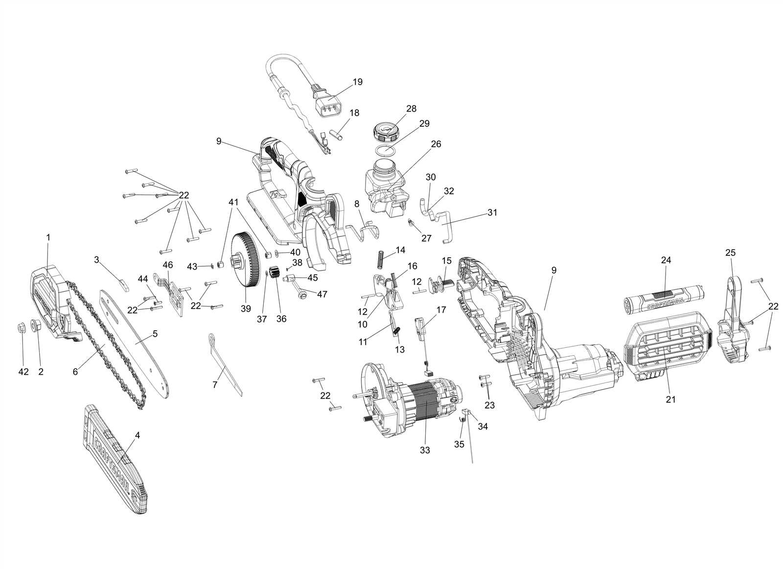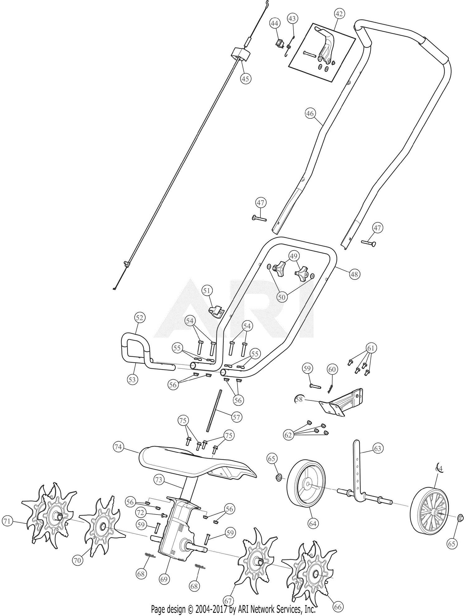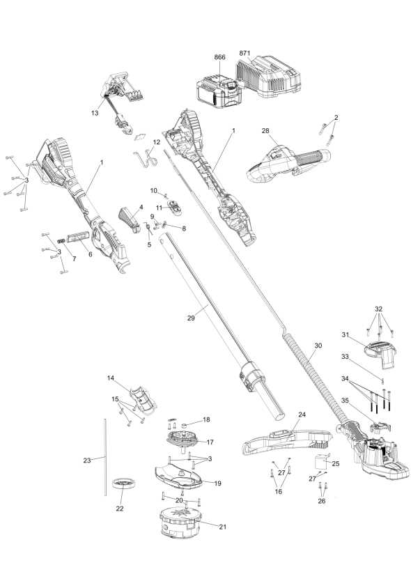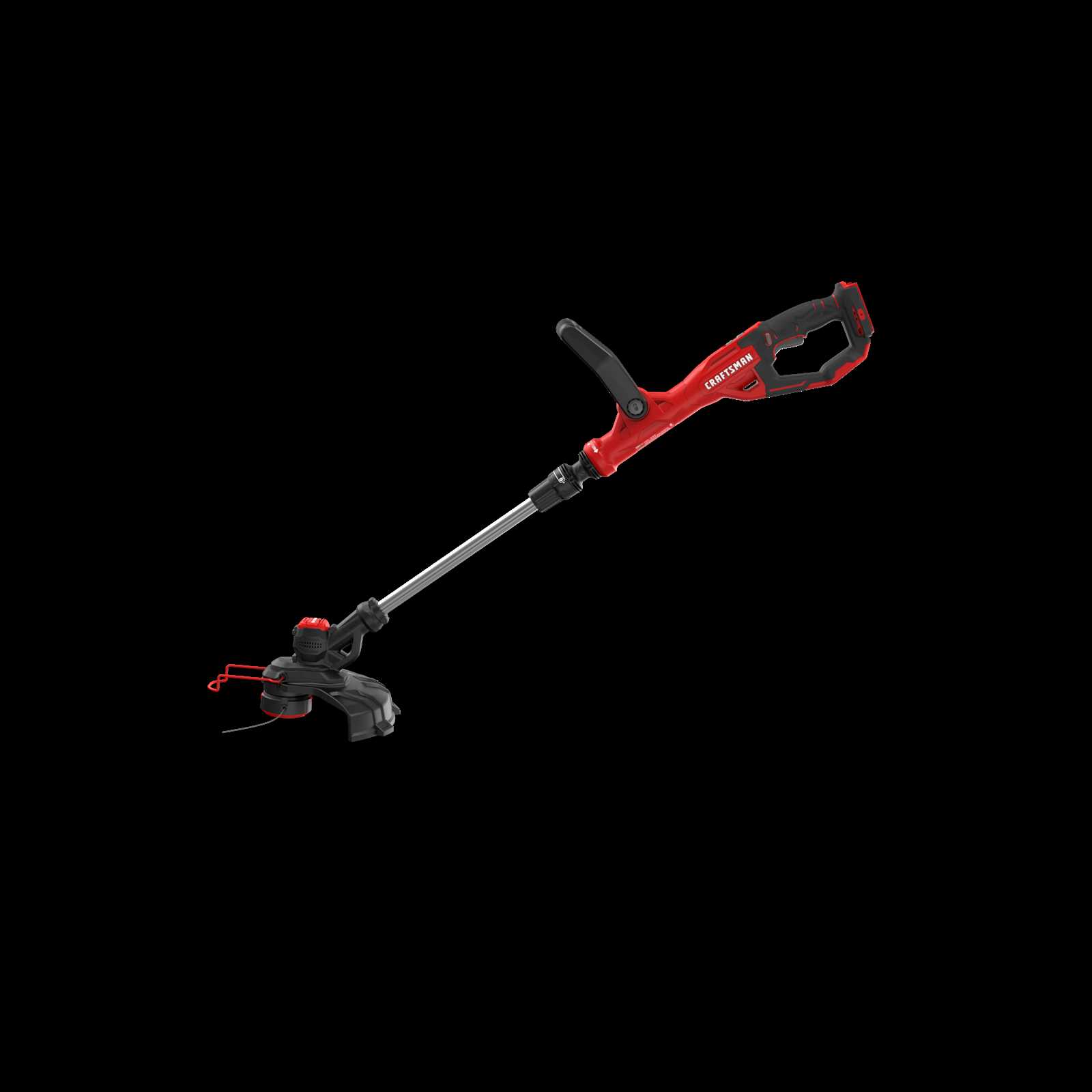
When maintaining or repairing devices, it’s crucial to have a clear understanding of how various elements are arranged and interconnected. This section will guide you through the intricacies of key mechanical and electrical configurations, offering a simplified approach to understanding the internal build of your equipment.
Whether you’re a seasoned technician or a first-time user, having access to accurate and detailed visual references can significantly ease the process of assembly, troubleshooting, and replacement. The following overview provides insight into the functional layout, helping you navigate complex setups efficiently.
We’ll dive into an organized breakdown, focusing on crucial connections and their relationships, ensuring you have the essential knowledge to keep your machine running smoothly. This guide is designed to enhance your ability to diagnose and maintain various components with confidence.
Overview of Key Components in CMCST900

The primary focus of this section is to explore the essential elements that form the core of the device. These components are designed to work in unison, ensuring optimal functionality and reliable performance. Understanding each of these elements can help users maintain and troubleshoot the system effectively.
Main Functional Units
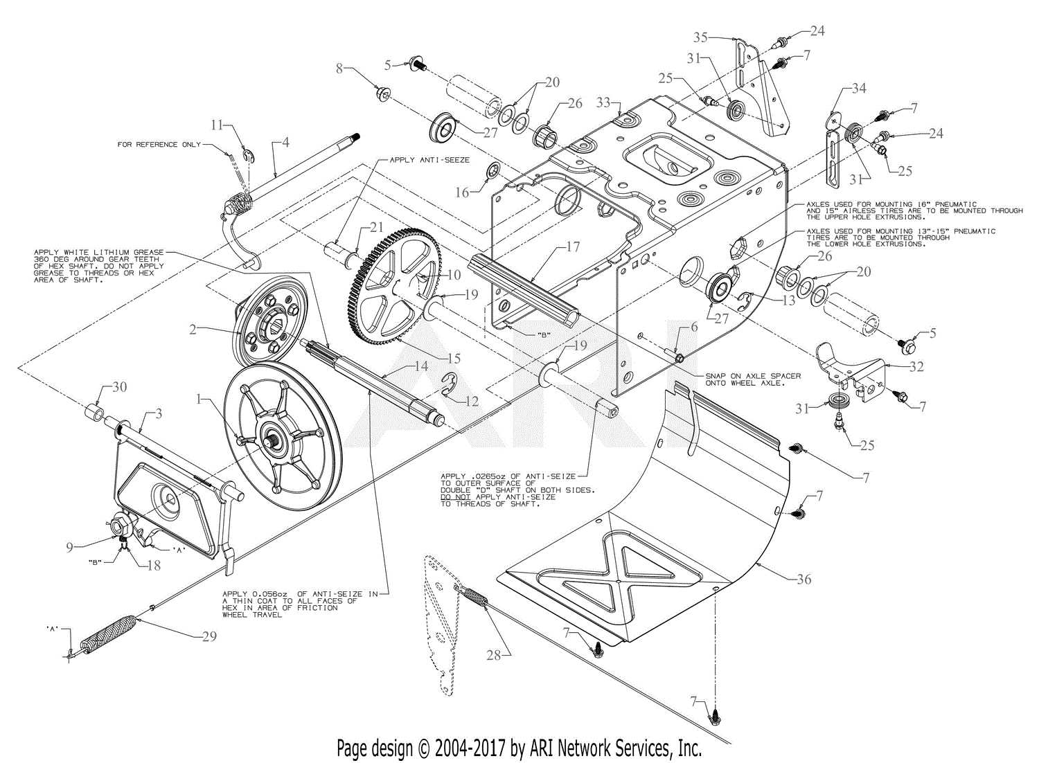
The device operates with several core units that contribute to its overall efficiency. These units include the power mechanism, control interface, and a cutting system. Each of these has been engineered for durability and smooth operation, ensuring that the equipment performs its intended tasks without interruption.
Supporting Features
In addition to the primary functional units, there are various auxiliary components that enhance the device’s usability. These include handles for ergonomic use, adjustable settings for customization, and safety features that protect both the equipment and the user during operation.
| Component | Function | ||||||||||||||||||
|---|---|---|---|---|---|---|---|---|---|---|---|---|---|---|---|---|---|---|---|
| Power Unit | Supplies energy to drive the system efficiently. | ||||||||||||||||||
| Control Interface | Allows users to adjust settings and monitor performance. |
| Component | Description |
|---|---|
| Handle | Provides a firm grip, designed for comfort and control during extended use. |
| Trigger | Activates the tool’s main function, offering precise control over the power output. |
| Lock Mechanism | Ensures the tool remains in a safe, idle state when not in use, preventing unintentional activation. |
| Adjustment Points | Allows customization of handle position to suit different users or specific tasks. |
By regularly inspecting and maintaining these elements, users can prolong the lifespan of their equipment and optimize performance. Proper adjustment and timely repairs will h
Line Feed System and Functionality
The automatic string advancement mechanism plays a crucial role in ensuring continuous and efficient trimming during operation. This system allows the cutting thread to extend as needed, eliminating the need for manual adjustments and interruptions.
Automatic Line Advancement is designed to adjust the length of the cutting thread while the tool is running, ensuring that the optimal length is maintained for precise and clean cutting. This process helps maintain a consistent performance throughout the job.
Key features of the system include its ability to detect when the cutting string shortens and automatically release additional line to maintain the necessary length. This function contributes to the overall ease of use and enhances productivity, especially during prolonged tasks.
Battery Mounting and Power Source Information
Understanding the integration of energy storage solutions is essential for optimal device performance. This section highlights crucial aspects related to the attachment of power units and the overall energy supply framework. Proper installation and maintenance can significantly enhance efficiency and longevity.
Installation Guidelines
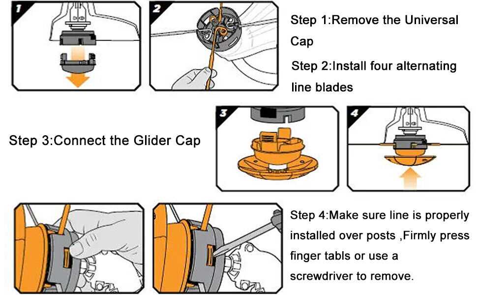
- Ensure the mounting area is clean and free of debris to promote a secure fit.
- Align the battery properly with the designated connectors to avoid damage.
- Use appropriate fastening mechanisms to hold the power source in place.
Maintenance Tips
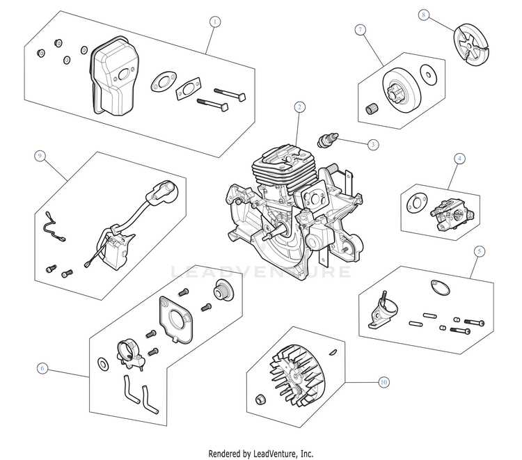
- Regularly inspect connections for corrosion or wear to ensure reliable performance.
- Keep the power source charged and avoid deep discharges to extend lifespan.
- Store in a cool, dry location when not in use to prevent deterioration.
Protective Guard and Cutting Path Overview
The safety features and operational layout of a cutting tool play a crucial role in ensuring user protection and effective performance. Understanding these elements is essential for optimal functionality and maintenance.
The protective cover serves as a vital component designed to shield the user from debris and potential hazards during operation. It is crucial for maintaining a safe working environment while facilitating visibility of the cutting area.
The cutting trajectory determines the tool’s efficiency and precision. A clear understanding of the designated cutting path enables users to achieve better results while minimizing the risk of accidents.
| Component | Description |
|---|---|
| Protective Guard | A safety feature that prevents debris from causing injury and enhances visibility of the cutting area. |
| Cutting Path | The predefined trajectory followed during operation, which affects accuracy and efficiency. |
| Adjustment Mechanism | Allows for modifications to the cutting path, providing flexibility based on the material being worked on. |
Maintenance Tips for Longevity
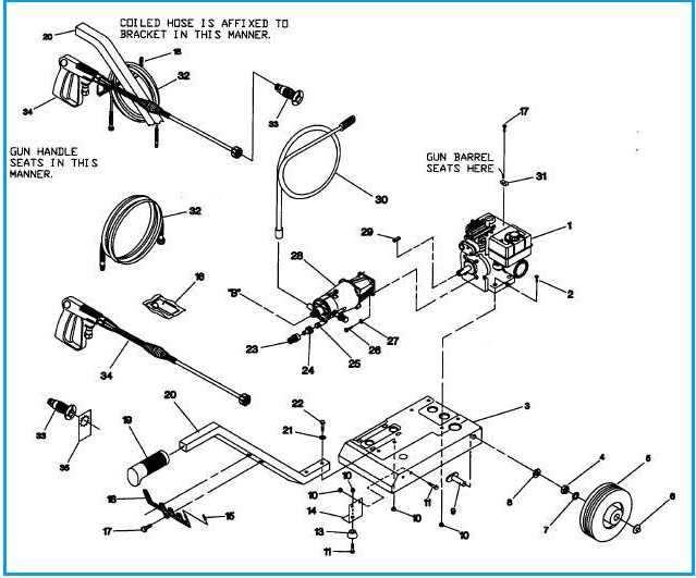
Ensuring the durability and efficient performance of your equipment requires regular upkeep and attention. Implementing effective maintenance practices can significantly extend the lifespan of your tools, reducing the need for repairs and replacements. This section provides practical advice to help you maintain your equipment in optimal condition.
Regular Cleaning
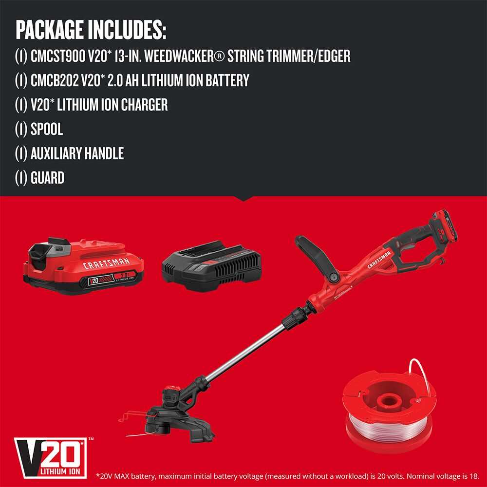
- Remove dust and debris after each use to prevent buildup.
- Use a soft cloth and mild cleaning solution for surfaces.
- Inspect and clean air filters regularly to enhance airflow.
Periodic Inspections
- Check for signs of wear or damage on components.
- Ensure that all fasteners and screws are securely tightened.
- Monitor performance for any unusual noises or vibrations.
By adhering to these maintenance practices, you can significantly enhance the reliability and longevity of your tools, ensuring they continue to perform effectively over time.
Replacing Worn or Damaged Elements
Over time, components within machinery can experience wear and tear, leading to decreased performance and efficiency. Identifying and replacing these compromised elements is essential to ensure optimal functionality and prolong the lifespan of the equipment. Understanding the signs of wear and knowing when to act can make a significant difference in maintenance efforts.
Signs of Wear and Damage
- Visible cracks or breaks in components
- Unusual noises during operation
- Decreased performance or efficiency
- Inconsistent operation or malfunctions
- Excessive vibration
Steps for Replacement
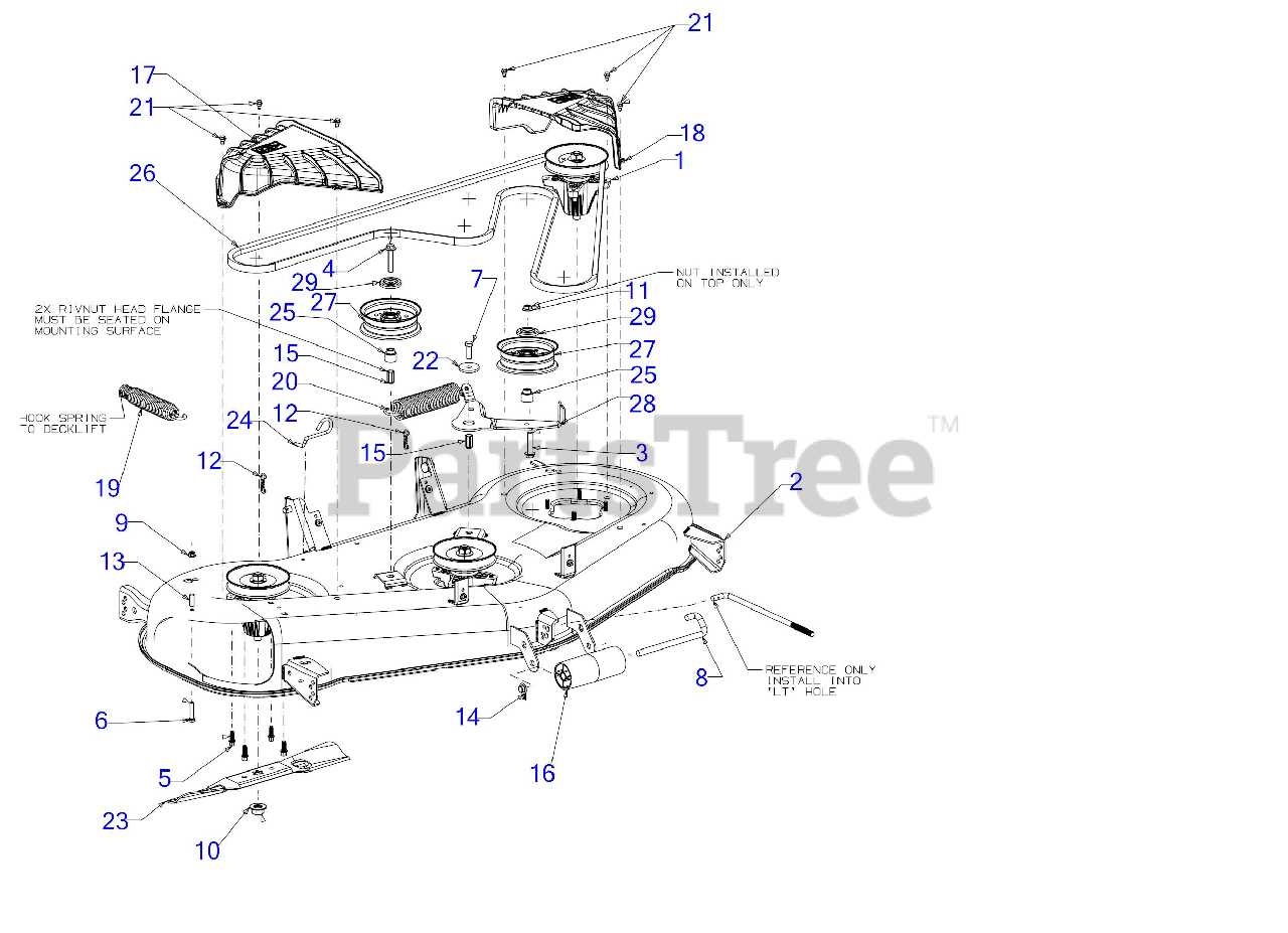
- Turn off the equipment and unplug it from the power source.
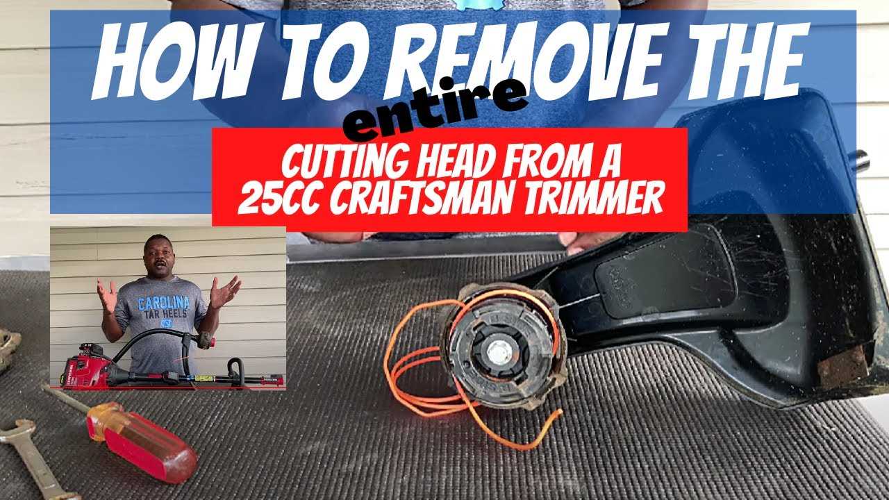
- Carefully disassemble the necessary components to access the damaged parts.
- Remove the worn or damaged elements, noting their orientation for replacement.
- Install new components, ensuring they are positioned correctly.
- Reassemble the equipment, verifying that all parts are securely fastened.
- Test the machinery to confirm proper operation.
