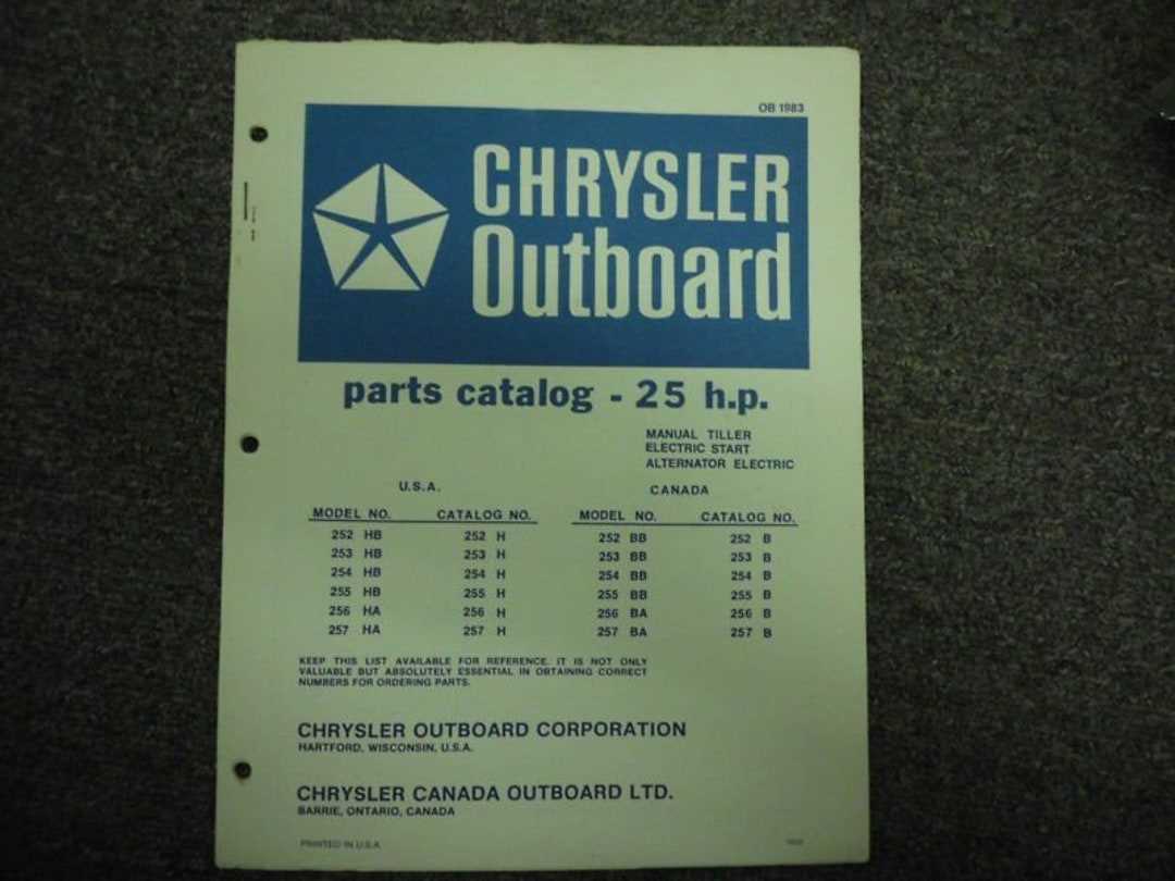
Understanding the structural organization of marine propulsion systems is crucial for ensuring optimal performance and longevity. By examining the key connections and placements within these systems, individuals can better maintain and repair their watercraft. A detailed exploration of each mechanism provides insights into how everything works together to propel a vessel smoothly and efficiently.
Each segment of these propulsion units plays a vital role in the overall operation. From the fuel system to the cooling channels, every component has a specific function that contributes to the seamless functioning of the marine engine. A thorough breakdown of the engine layout helps users identify crucial areas for maintenance or replacement, ensuring that their equipment stays in top condition for a long time.
Familiarizing oneself with the configuration of various components can make repairs and upgrades more straightforward. This guide aims to offer a
Understanding Key Components of Chrysler Outboard Motors
When exploring the mechanics of propulsion systems used in marine vessels, several critical elements play a role in ensuring optimal performance. The configuration of these elements impacts the efficiency, power, and durability of the entire system, making it essential to grasp how each part contributes to the overall functionality.
Engine Block and Power Delivery
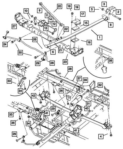
The core of the system lies in its central power unit, responsible for converting energy into mechanical movement. This component works alongside the ignition and fuel mechanisms, driving the necessary force to propel the vessel. Effective power delivery is achieved through precise synchronization between multiple parts, ensuring smooth operation.
Cooling and Lubrication Systems
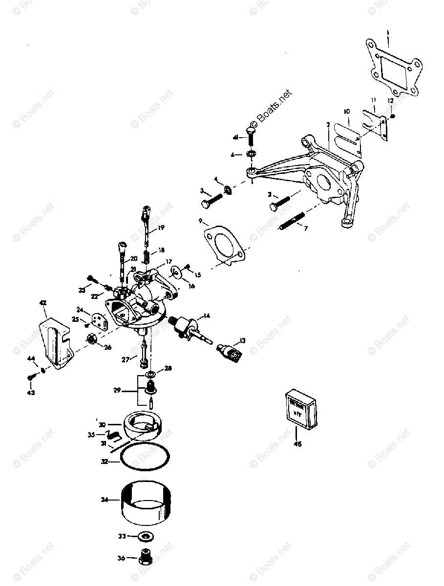
Another crucial aspect involves the regulation of temperature and friction. Cooling channels and lubricants help maintain the engine’s internal conditions, preventing overheating and reducing wear. These systems are designed to circulate fluids efficiently, preserving the longevity and reliability of the machine.
How to Interpret an Outboard Parts Diagram
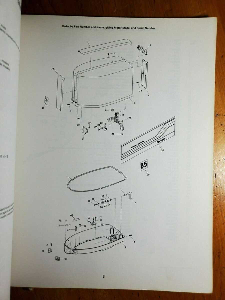
Understanding a technical illustration of engine components is essential for anyone involved in maintenance or repair. By correctly analyzing such visuals, you can identify specific elements, their positioning, and connections, allowing for accurate replacements or fixes. This guide will walk you through the key aspects to focus on when reviewing these diagrams to ensure a thorough and informed approach.
Key Sections of the Diagram
- Main Components: These represent the essential elements that form the core of the engine system. Recognizing them is crucial for identifying what needs attention.
- Support Structures: These typically include the surrounding frameworks or casings that hold other elements in place. Knowing how they interact with the main units can help in understanding the entire setup.
- Connection Points: Bolts, joints, and fasteners are often shown to illustrate how different parts link together. Properly recognizing these ensures safe disassembly and reassembly.
How to Follow Numbered Labels
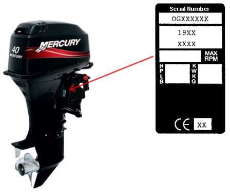
- Identify the legend
Commonly Replaced Parts in Chrysler Engines
Over time, various components of marine motors can wear out due to regular use, exposure to water, and other environmental factors. Understanding which elements typically require attention helps boat owners maintain the engine’s longevity and ensure optimal performance.
- Gaskets: Seals are crucial for preventing leaks in key areas, and they often need replacement due to degradation from heat and pressure.
- Fuel Filters: These protect the engine by ensuring that only clean fuel reaches the internal mechanisms, and replacing them regularly is vital for smooth operation.
- Impellers: Essential for cooling, the impeller tends to wear out, especially when exposed to debris or inadequate water flow.
- Spark Plugs: These are responsible for ignition and tend to wear over time, impacting efficiency if not replaced when needed.
- Thermostats: Temperature control units that, if malfunctioning, can cause overheating or poor engine performance.
Regular inspection and timely replacements of these items ensure smoother operation and prevent more severe issues from arising.
Exploring the Functionality of Cooling Systems
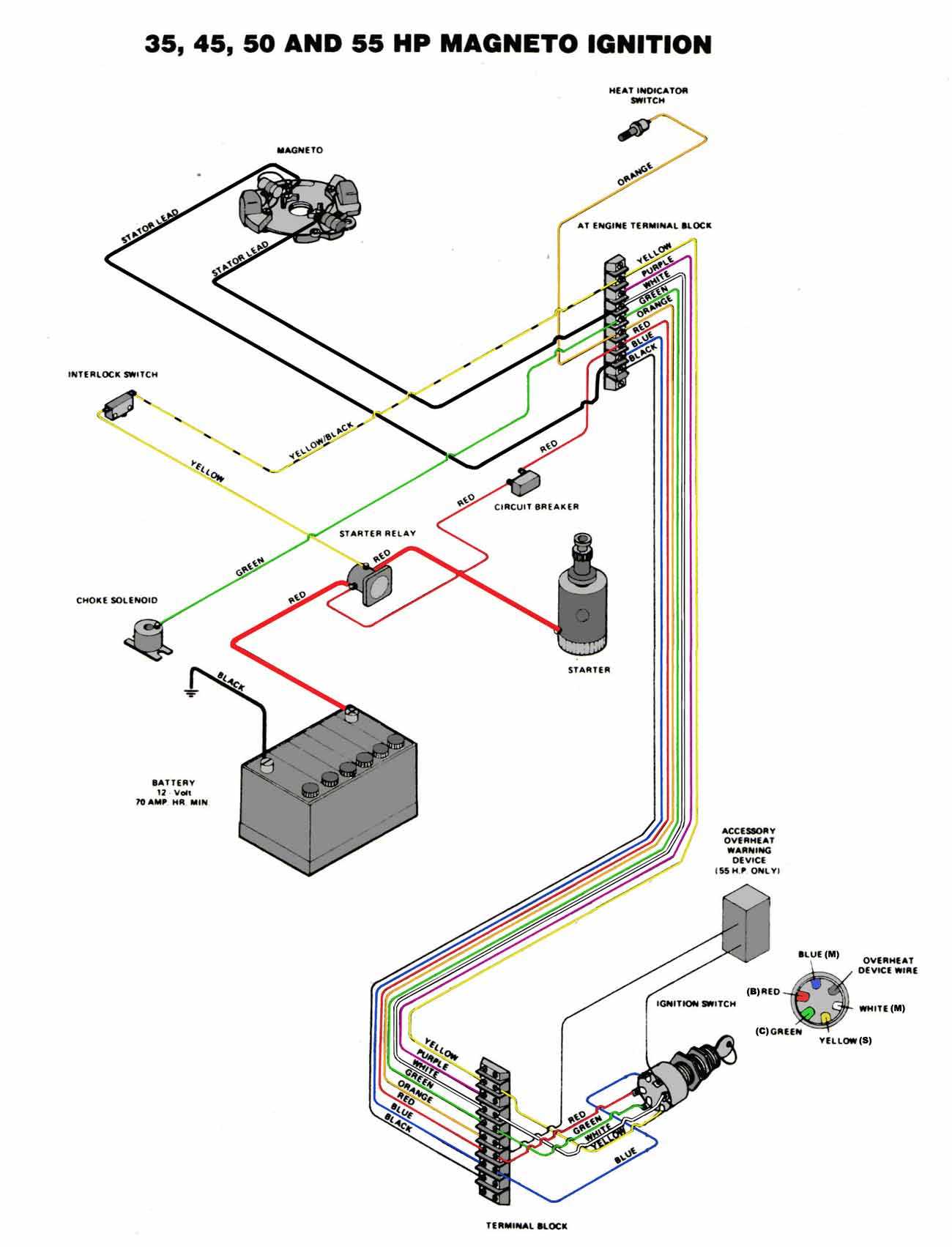
Efficient temperature regulation is critical to the operation of any mechanical engine. A well-designed cooling mechanism ensures that components maintain optimal performance by preventing excessive heat build-up. Without proper control, rising temperatures can lead to severe damage and reduced efficiency.
At the core of these systems is a network designed to move heat away from crucial elements, maintaining a balance between thermal buildup and dissipation. This process relies on the circulation of a specific medium to absorb and transfer excess heat. As this medium moves through the system, it draws energy away from heated surfaces, allowing the engine to operate at safe and stable conditions.
Various components collaborate to keep temperatures in check, ensuring smooth operation. This includes the movement of coolant, the transfer of heat through specialized pathways, and the expulsion of excess energy through outlets. Together, these processes form a cohesive system that protects vital engine functions from overheating, enabling sustained performance.
Ignition System Breakdown for Chrysler Models
The ignition mechanism in these models plays a crucial role in ensuring the engine starts and runs smoothly. This system is responsible for generating the necessary energy to ignite the fuel-air mixture, which powers the motor. Each component within the setup must function in harmony to guarantee optimal performance. From the energy generation unit to the timing control, every part contributes to a seamless operation.
Key Components involved in this system include energy generation devices, wiring assemblies, and control units. Each element is designed to manage the flow of current and ensure precise timing. A well-maintained setup ensures reliability, minimizes the risk of malfunctions, and supports longevity.
Common issues that arise within this system often stem from wear or improper maintenance. Faults in connectors, irregular energy flow, or timing misalignment can lead to reduced efficiency. Regular inspections and timely replacements are essential for maintaining optimal performance.
Identifying Fuel System Components in Diagrams
Understanding the layout of the fuel system can be crucial for ensuring proper maintenance and troubleshooting. Diagrams are a valuable tool for recognizing key elements that enable the flow of fuel, contributing to the engine’s efficiency and performance. By familiarizing yourself with these visual representations, you can more easily pinpoint the necessary components and their locations.
Among the primary elements to locate are the fuel tank, hoses, and filtration mechanisms, which ensure a steady and clean fuel supply. Additional elements, such as connectors, valves, and regulators, manage the pressure and direction of the fuel as it moves through the system. Each component plays a specific role in maintaining the system’s overall functionality.
Being able to identify these individual elements not only helps with part replacement but also aids in diagnosing potential issues that may arise due to wear or malfunction. A clear understanding of the connections between the various components ensures that repairs are made effectively and that the system operates smoothly.
Step-by-Step Guide to Gear Assembly
This section provides a comprehensive overview of the assembly process for the gearing mechanism found in marine engines. Understanding the steps involved ensures a smoother operation and enhances the overall efficiency of the system. Proper assembly is crucial for optimal performance and longevity of the components.
Preparation and Tools
Before beginning the assembly, gather all necessary tools and components. Essential tools typically include wrenches, screwdrivers, and specialized equipment for alignment. Ensure that all components are clean and free of debris to prevent any interference during assembly.
Assembly Procedure
Start by carefully aligning the gears according to the manufacturer’s specifications. Gradually tighten the screws or bolts, ensuring even pressure to avoid any misalignment. Once all components are securely in place, perform a thorough inspection to confirm that everything functions smoothly. Finally, test the assembly by rotating the gears manually to check for any irregularities or resistance.
Note: Always refer to the specific guidelines provided by the manufacturer for detailed instructions and torque specifications to achieve the best results.
Maintaining the Propeller and Lower Unit
Proper care of the propulsion system and its associated components is essential for ensuring optimal performance and longevity. Regular maintenance not only enhances efficiency but also minimizes the risk of potential failures. By adhering to a structured approach, you can ensure that these critical elements remain in peak condition.
Inspection is the first step in this process. Check for any signs of wear, corrosion, or damage on the propeller and lower unit. Look for nicks or dents on the blades, as these can affect the overall functionality. Additionally, inspect the housing for cracks or signs of leakage that could lead to more serious issues.
Cleaning should follow the inspection. Remove any debris, such as weeds or sand, that may have accumulated. A thorough clean helps to prevent fouling and improves performance. Use fresh water and a gentle brush to avoid damaging surfaces.
Lubrication is vital for the moving parts within the lower assembly. Ensure that all bearings and seals are adequately lubricated with appropriate marine grease. This practice helps to reduce friction and wear, extending the lifespan of the components.
Finally, storage practices play a significant role in the durability of the system. When not in use, consider raising the unit out of the water to prevent prolonged exposure to harsh elements. Covering the propeller can also shield it from environmental factors, further enhancing its lifespan.
Troubleshooting Engine Issues Using Diagrams
Diagnosing problems in mechanical systems can often be a challenging task. Utilizing visual representations of components and their relationships can significantly enhance the troubleshooting process. These illustrations serve as a guide, allowing technicians to identify potential malfunctions and pinpoint the sources of issues effectively.
Identifying Common Problems
Visual aids can help users recognize prevalent symptoms and correlate them with specific components. By cross-referencing observed behaviors with detailed visuals, one can systematically rule out various elements and focus on those most likely to be at fault. This method not only streamlines the diagnostic process but also minimizes the chances of overlooking critical issues.
Step-by-Step Analysis
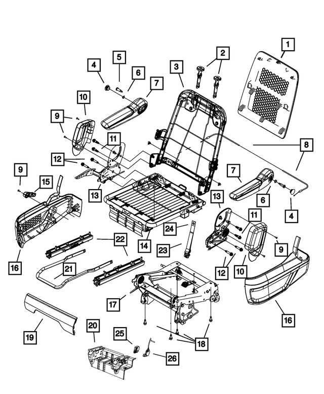
Employing systematic visuals allows for a structured approach to resolving mechanical difficulties. Each segment of the system can be examined in isolation, facilitating a thorough investigation of each component’s functionality. By following a logical sequence, users can trace problems back to their origins, ensuring that repairs are both accurate and efficient.