Understanding the structure and key elements of processing equipment is crucial for ensuring smooth and efficient operations. By familiarizing yourself with how various components interact, you can easily maintain and enhance the functionality of your device, reducing the likelihood of breakdowns and improving overall performance.
The configuration and arrangement of internal mechanisms play a significant role in how effectively the device operates. Each element, whether large or small, contributes to the overall functionality and durability. Regular maintenance and proper handling of these mechanisms are essential for extending the lifespan of your equipment.
In the following sections, we’ll explore the different segments and their roles, providing detailed insights into each element’s purpose and how it impacts the efficiency of your system. By gaining a deeper understanding, you’ll be better equipped to perform routine maintenance, replace worn-out pieces, and troubleshoot common issues.
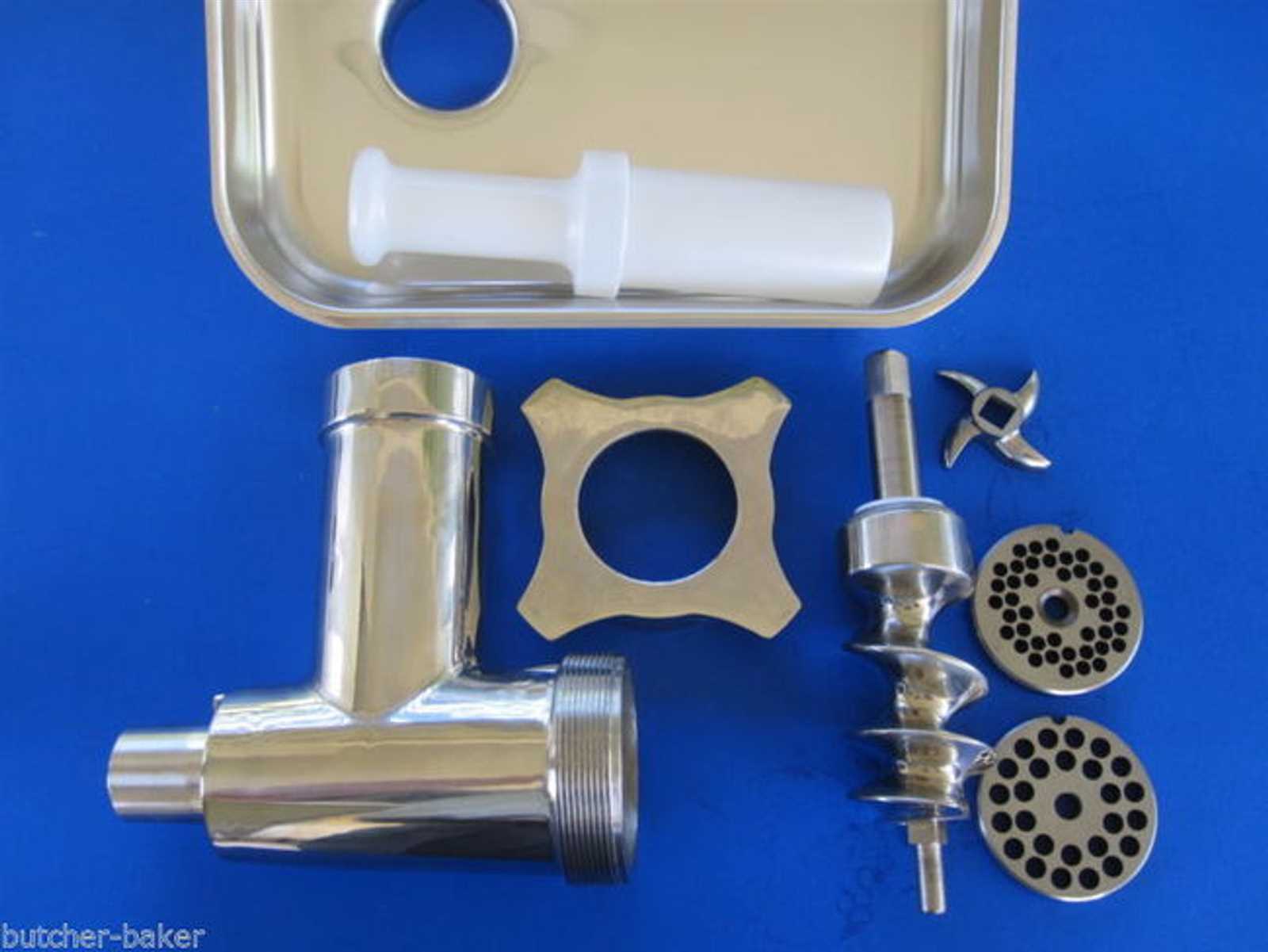
Overview of Hobart Meat Grinder Components
The following section provides a comprehensive look at the key elements that make up the structure of this industrial-grade equipment. Each component plays a vital role in ensuring efficient operation, contributing to the overall durability and performance. Understanding the arrangement of these elements helps in maintaining the system and ensuring long-lasting functionality.
| Component | Description |
|---|---|
| Motor Unit | The powerhouse responsible for driving the entire system, ensuring smooth and consistent performance. |
| Processing Chamber | This section houses the raw materials and directs them through the necessary processing stages. |
| Blades and Cutters | Sharp elements designed to break down materials with precision, contributing to the final product’s texture. |
| Feed Mechanism | Ensures continuous input of materials, regulating the flow for optimal processing efficiency. |
| Output Discharge | The final stage where processed materials are collected, ready for packaging or further use. |
Main Housing Structure and Functions
The central casing serves as the core framework, ensuring stability and protection for the internal mechanisms. It is designed to support all operational components, allowing for efficient and secure functioning. The structure plays a crucial role in safeguarding the machine’s elements from external factors and wear, contributing to its longevity and reliability.
Core Elements of the Housing
- External Frame: The robust exterior shell provides a protective barrier, preventing damage and ensuring the durability of internal parts.
- Support System: The internal supports are designed to hold and align components, maintaining precision and minimizing vibrations during operation.
- Sealing Mechanism: The enclosure often includes seals or gaskets to prevent debris from entering and to maintain cleanliness within the system.
Functions of the Housing
- Structural Integrity: The housing ensures that all internal components are securely fastened and positioned correctly for optimal performance.
- Protection: It shields sensitive internal parts from physical damage and environmental factors, such as moisture and dust.
- Maintenance Facilitation: The design often allows for easy disassembly and reassembly, simplifying routine cleaning and upkeep.
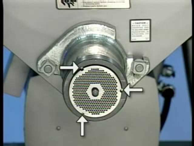
Exploring the Grinder Plate Variants
The variety of plate options available can significantly impact the overall performance of your machine. Each type is designed for specific purposes, ensuring that the final result meets the desired consistency and texture. Understanding the differences between these plates helps you choose the right one for your needs, optimizing both efficiency and output quality.
- Fine Plate: This option is ideal for producing smooth, uniform results, often used for creating delicate textures.
- Medium Plate: A versatile choice, the medium plate strikes a balance between fine and coarse options, offering a consistent texture suitable for various tasks.
- Coarse Plate: When a chunkier consistency is required, the coarse plate provides larger cuts, perfect for tasks requiring less precision.
Each of these plates can be swapped out depending on your specific needs, allowing for flexibility and customization in your work process.
Detailed Breakdown of Cutting Blade Parts
The cutting blade plays a crucial role in ensuring efficient processing. It’s composed of several distinct components, each contributing to its overall performance. Understanding how these elements work together can help maintain smooth operation and prevent malfunctions. Proper care and regular inspection of each component are essential for longevity and functionality.
Blade Edge: The sharpened edge is responsible for precision cuts, ensuring clean and consistent results. Over time, the edge may dull, requiring regular sharpening or replacement to maintain effectiveness.
Central Hub: This part secures the blade in place, allowing it to rotate evenly during use. It’s vital for maintaining balance and preventing unnecessary wear on surrounding components.
Attachment Points: These are the areas where the blade connects to the machine. Secure attachment is necessary for smooth operation, and loose connections can lead to inefficiency or damage.
Proper maintenance and understanding of each part’s function are key to ensuring the cutting blade performs optimally and lasts longer.
Feed Tube Assembly and Its Role
The feed tube assembly plays a crucial function in guiding the material smoothly into the processing system. This component ensures an even and consistent flow, preventing any blockages or interruptions that might affect performance. By channeling the input through a well-structured passage, the assembly guarantees efficiency in operation, making it a key element in the overall mechanism.
Structural Importance: The design of the feed tube allows for optimal movement, directing the contents precisely where needed. This precision enhances productivity and reduces the risk of jams or malfunctions, contributing to a smoother workflow.
Proper Maintenance is essential to keep the feed tube functioning efficiently. Regular inspection and cleaning of this component help maintain its performance and extend the longevity of the entire system.
Motor Functionality in Hobart Grinders
The efficiency and reliability of food processing machines largely depend on their motor systems. In these devices, the motor plays a crucial role, serving as the primary source of power that drives various components, ensuring smooth operation and consistent performance. Understanding how the motor functions can provide valuable insights into the overall effectiveness of the equipment.
Typically, the motor operates through the following mechanisms:
- Power Transmission: The motor converts electrical energy into mechanical energy, facilitating the movement of blades and other parts.
- Speed Regulation: Many models feature adjustable speed settings, allowing operators to control the rate of processing based on specific requirements.
- Overload Protection: Advanced motor systems often include safety features that prevent overheating and damage, ensuring longevity.
Proper maintenance of the motor is essential for optimal functionality. Regular checks and timely servicing can help identify potential issues before they escalate. Here are some recommended practices:
- Inspect electrical connections and wiring for signs of wear.
- Clean the motor housing to prevent dust buildup.
- Lubricate moving parts as per the manufacturer’s guidelines.
Understanding the motor’s functionality not only enhances performance but also contributes to the durability of the equipment, making it an essential aspect of operation.
Maintenance of Auger and Shaft Elements
Regular upkeep of the feed mechanism and its connecting components is essential for ensuring optimal performance and longevity of the equipment. These elements play a critical role in facilitating efficient material movement, and their proper maintenance can significantly impact operational efficiency. This section outlines best practices for caring for these vital components, promoting their durability and functionality.
To maintain the auger and shaft effectively, it’s crucial to follow a systematic approach. Routine inspections should be conducted to identify any wear or damage, and immediate attention should be given to any abnormalities. Cleaning these elements from debris and residue will also help prevent blockages and ensure smooth operation.
| Maintenance Task | Frequency | Description |
|---|---|---|
| Inspection | Weekly | Check for signs of wear, cracks, or other damage. |
| Cleaning | After Each Use | Remove all residues and debris to prevent blockages. |
| Lubrication | Monthly | Apply appropriate lubricant to ensure smooth movement. |
| Tightening Fasteners | Monthly | Ensure all bolts and screws are secure to prevent looseness. |
By adhering to these maintenance practices, the efficiency and reliability of the feed mechanism and its associated elements can be significantly enhanced, leading to improved operational performance.
Understanding the Safety Features
Ensuring a safe working environment is crucial when operating machinery designed for food preparation. These devices incorporate various safety mechanisms to protect users from potential hazards. Understanding these features not only enhances user safety but also promotes efficient and responsible usage of the equipment.
Emergency Stop Mechanisms

One of the essential safety features found in these machines is the emergency stop function. This allows users to quickly halt operations in case of unexpected situations, minimizing the risk of injury. The placement of the emergency stop button is strategically designed for easy access, ensuring that operators can react swiftly when needed.
Protective Guards and Shields
Another critical aspect of safety involves the use of protective barriers. These guards are designed to prevent accidental contact with moving components, significantly reducing the likelihood of accidents. Regular inspection and maintenance of these protective features are essential to ensure they remain effective and intact during operation.
Replacing Worn Out Seals and Gaskets
Maintaining optimal performance in any machinery often hinges on the condition of its seals and gaskets. Over time, these components may wear down, leading to leaks and inefficiencies. Regular inspection and timely replacement are crucial to ensure that the equipment operates smoothly and effectively.
Identifying Signs of Wear
Before proceeding with the replacement process, it’s important to recognize the indicators of degraded seals and gaskets. Common signs include:
| Indicator | Description |
|---|---|
| Leaking Fluids | Presence of liquids around joints or connections suggests seal failure. |
| Visible Cracking | Cracks or splits on the surface of seals indicate they need replacement. |
| Unusual Noise | Increased noise levels during operation may point to gasket deterioration. |
Replacement Process
Once you have identified worn components, follow these steps for effective replacement:
- Gather necessary tools and replacement components.
- Carefully remove the old seals and gaskets, ensuring not to damage surrounding areas.
- Clean the surfaces to remove any debris or residue.
- Install the new seals and gaskets, ensuring proper alignment.
- Reassemble the unit and test for leaks or irregularities.