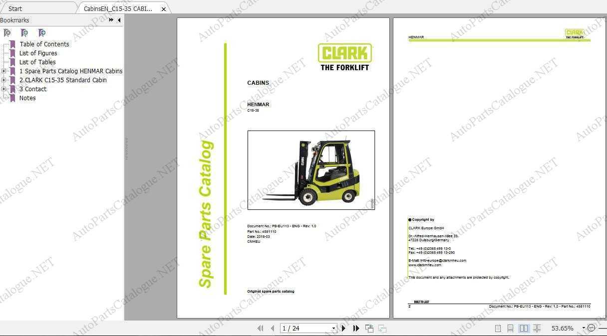
In today’s fast-paced industrial environments, efficiency and proper maintenance of machinery are key to smooth operations. A clear and well-organized visual representation of mechanical elements plays a crucial role in ensuring that routine servicing and repairs are carried out seamlessly. With a clear guide, technicians can easily identify the necessary components and ensure that each part is functioning optimally.
The layout of internal mechanisms in heavy-duty machines can seem complex at first glance. However, with the right approach and understanding, pinpointing specific mechanical pieces becomes much more straightforward. This guide provides an overview of how various elements are structured within these machines, allowing for better planning and more effective problem-solving.
Whether you’re looking to understand the arrangement of intricate mechanisms or need to locate a specific element for maintenance
Understanding the Structure of a Forklift
The design of industrial lifting machines is centered around functionality, ensuring they can handle a wide range of tasks efficiently. These vehicles are carefully engineered to combine stability, power, and versatility, making them essential in many industries. To fully understand their operation, it’s important to break down the key components and how they interact.
- Chassis: The foundation that provides support and houses other critical elements.
- Mast: The vertical assembly that raises and lowers loads, powered by hydraulic systems.
- Counterweight: A heavy block that ensures balance during lifting by offsetting the load.
- Control system: Allows the operator to manage lifting, tilting, and movement, ensuring precision and safety.
- Power source: Usually driven by fuel or electricity, enabling the vehicle’s movement and functionality.
Each part plays a critical role in ensuring the smooth and safe operation of these machines, contributing to their effectiveness in industrial settings.
Key Components of Industrial Lifting Equipment
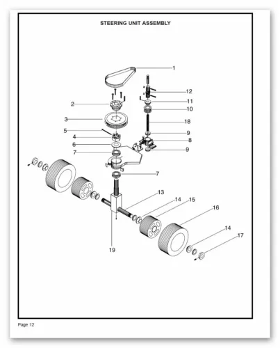
Efficient and durable material handling machines rely on various essential elements working together. These machines are built for strength, precision, and endurance, making each component crucial to their overall functionality. Below is an overview of the most important elements that ensure smooth operation and optimal performance in heavy-duty lifting devices.
- Hydraulic System: This system powers the lifting mechanism, allowing for the smooth and precise elevation of loads.
- Drive Motor: Responsible for propelling the machine forward and backward, the motor is key to mobility and efficiency.
- Mast Assembly: The vertical structure that enables the elevation and lowering of heavy materials, ensuring stability during operations.
- Transmission: Facilitates the transition between speeds and directions, ensuring smooth movement and load handling.
- Counterweight: A heavy mass located at the rear, balancing the load at the front and preventing tipping during operation.
How to Identify Parts on a Diagram
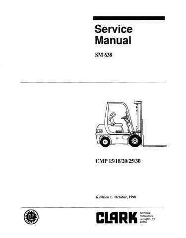
Understanding how to locate individual components within a schematic is crucial for ensuring proper maintenance and repairs. The visual layout of such technical illustrations often includes symbols and labels that represent specific elements, and learning to interpret them efficiently saves time and reduces errors.
| Symbol | Meaning | Location |
|---|---|---|
| Circle | Indicates a connection point | Found at intersections of lines |
| Square | Represents a mechanical element | Often located in the central area |
| Arrow | Shows direction of movement | Typically near moving components |
When reviewing such layouts, pay close attention to the labeling system, which often includes codes or numbers that correspond to a list or key. Familiarizing yourself with this system makes it easier to understand what each part of the illustration represents, allowing you to identify the necessary elements quickly.
Hydraulic System in Clark Forklifts
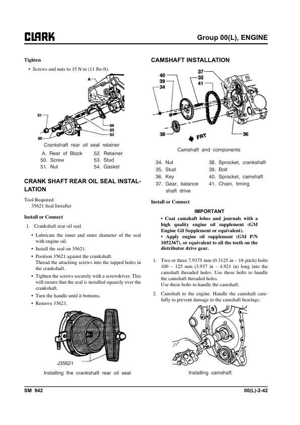
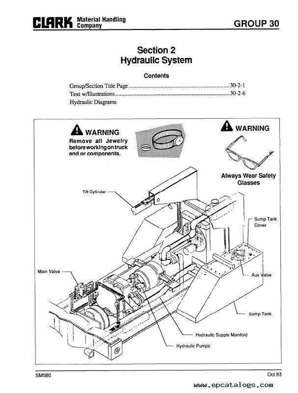
The hydraulic mechanism plays a crucial role in the efficient operation of lifting machinery. This system ensures smooth, controlled movement of the lifting components, allowing for precise handling and enhanced productivity. Proper maintenance and understanding of its functions are essential to avoid downtime and ensure safe operation.
- The system consists of a series of interconnected valves, pumps, and cylinders.
- Each component is responsible for converting fluid power into mechanical energy.
- The hydraulic fluid moves through these elements, creating the force needed to lift heavy loads.
- Pressure regulation is key to maintaining optimal performance and avoiding leaks or malfunctions.
Regular checks on fluid levels, pump integrity, and valve conditions help in prolonging the life of the system and ensuring efficient operation.
Drive System Layout and Function
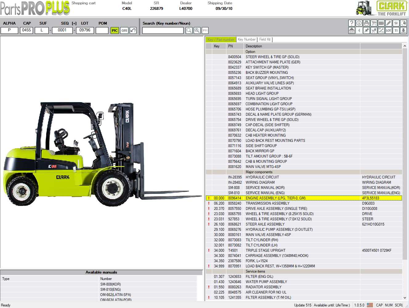
The drive system is essential for transferring power from the engine to the wheels, ensuring smooth movement and operation. It consists of several interconnected components that work together to convert mechanical energy into motion. Understanding how these elements interact is key to maintaining efficiency and performance.
The layout of the drive mechanism is designed to maximize power transmission while minimizing energy loss. Each component, from the transmission to the axles, plays a critical role in ensuring that power is effectively delivered to the wheels, allowing for precise control and handling.
The primary function of the drive system is to regulate speed, torque, and direction of movement. By coordinating the engine’s output with the demands of the terrain and load, the system ensures stable and reliable operation in various conditions.
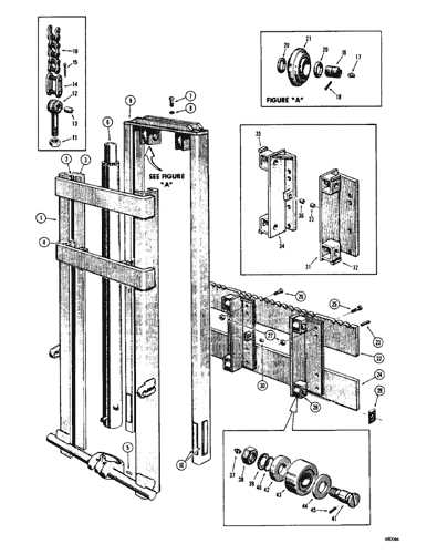
Detailed View of the Mast Assembly
The mast assembly is a critical component in material handling machinery, responsible for elevating and lowering loads efficiently. Understanding its structure and functionality is essential for ensuring optimal performance and safety during operation.
This assembly typically consists of several key elements that work together to provide stability and lifting capability:
- Vertical Channels: These support the overall structure and guide the movement of the lifting mechanism.
- Carriage: This component secures the load and allows it to be raised or lowered smoothly.
- Lift Cylinder: This hydraulic element provides the necessary force to elevate the load.
- Forks: Attached to the carriage, these are designed to support and transport various items.
Regular maintenance of the mast assembly is crucial to prevent wear and tear. Key practices include:
- Inspecting for signs of damage or corrosion.
- Lubricating moving parts to ensure smooth operation.
- Checking hydraulic fluid levels and replacing as needed.
By focusing on these elements and maintenance practices, operators can enhance the longevity and efficiency of the mast assembly, contributing to safer and more effective handling of materials.
Common Wear Parts and Their Location
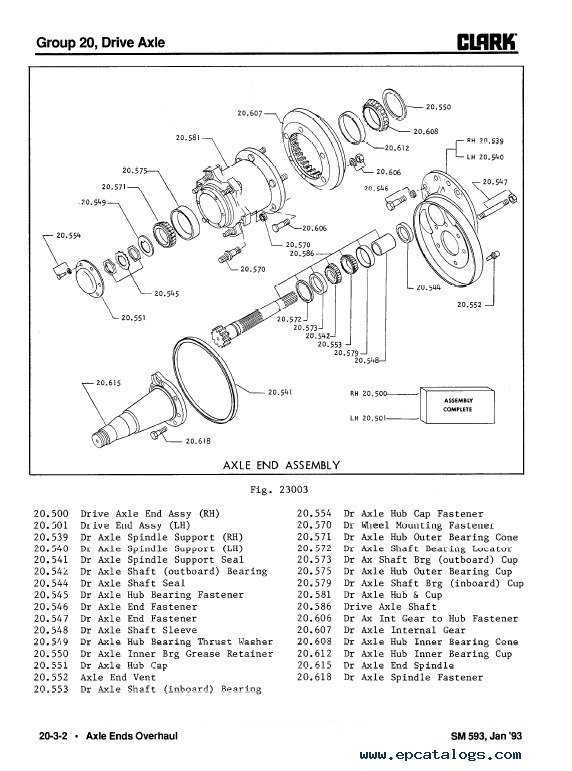
In every lifting vehicle, certain components experience frequent usage and subsequently exhibit signs of wear over time. Understanding the typical areas that are prone to deterioration can help in maintaining optimal performance and ensuring safety. Identifying these crucial elements is essential for effective upkeep.
Key Components Subject to Wear
Among the most commonly affected elements are the tires, which endure constant contact with the ground. Their condition directly influences traction and stability. Additionally, the hydraulic hoses are vital for proper lifting operations and must be regularly inspected for leaks or signs of fraying.
Maintenance and Inspection Points
Regular maintenance should include a thorough examination of the wheel bearings, as they support the vehicle’s weight and ensure smooth movement. Moreover, checking the drive chain and brakes is crucial; these components are integral for safe operation and require periodic adjustments to function efficiently.
Electrical System Overview for Clark Models
The electrical framework of these machinery units plays a crucial role in their efficient operation and functionality. This system encompasses various components that work collaboratively to ensure optimal performance, enabling the vehicle to carry out its tasks seamlessly.
At the heart of the electrical system lies the power source, typically a battery, which supplies the necessary energy for all electrical functions. This component is vital for starting the engine and powering the various systems within the equipment.
In addition, a network of wiring connects different elements, facilitating communication and energy transfer. Proper maintenance and inspection of these connections are essential to prevent electrical failures that could hinder operations.
Another significant aspect is the control unit, which manages the flow of electricity throughout the system. This unit ensures that each component receives the appropriate voltage and current, allowing for smooth and efficient machinery operation.
Furthermore, the inclusion of safety features such as fuses and circuit breakers helps protect the electrical system from overloads and short circuits, enhancing the overall reliability and safety of the machinery.
Finding Replacement Parts Using Diagrams
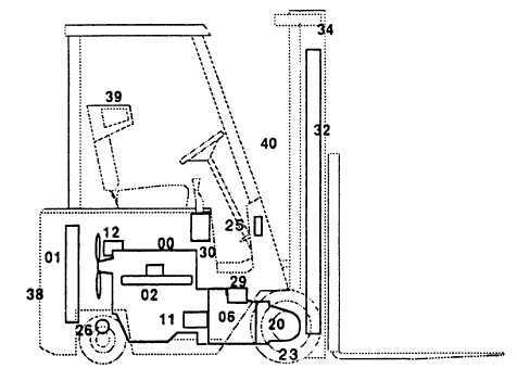
Locating suitable components for machinery can be a daunting task. Utilizing visual aids that illustrate the various elements of a machine simplifies this process. These illustrations provide a clear reference, making it easier to identify the necessary components for repair or maintenance.
Understanding Visual References
Visual references serve as a crucial tool in comprehending the assembly and arrangement of machinery. They help users:
- Identify specific components quickly
- Understand the relationship between various elements
- Enhance accuracy in ordering replacements
Steps to Effectively Use Visual Aids

To maximize the benefits of these illustrations, follow these steps:
- Examine the illustration thoroughly to familiarize yourself with the layout.
- Identify the part you need by comparing it with the visuals.
- Note any part numbers or descriptions for accurate ordering.
- Consult suppliers or retailers with this information to ensure you receive the correct component.