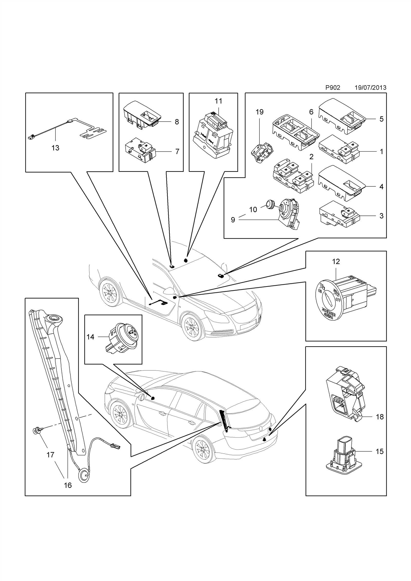
The intricate system of elements within electronic devices requires a clear and precise layout to ensure seamless operation and troubleshooting. This section delves into how to understand and utilize various schematics to pinpoint the arrangement of essential components, making repairs and upgrades more efficient.
When working with intricate machinery, it’s crucial to have a detailed map of where each essential piece resides. With this knowledge, identifying faulty units and replacing them becomes a straightforward task, minimizing downtime and ensuring the longevity of the equipment.
Through a systematic approach, identifying each module’s role in the overall functioning of the system becomes more manageable. This clarity allows users to navigate complex structures with confidence, making maintenance an easier and more effective process.
By mastering these visual guides, individuals can approach equipment management with greater confidence, avoiding unnecessary confusion and enhancing overall productivity.
Understanding Insignia Parts Overview
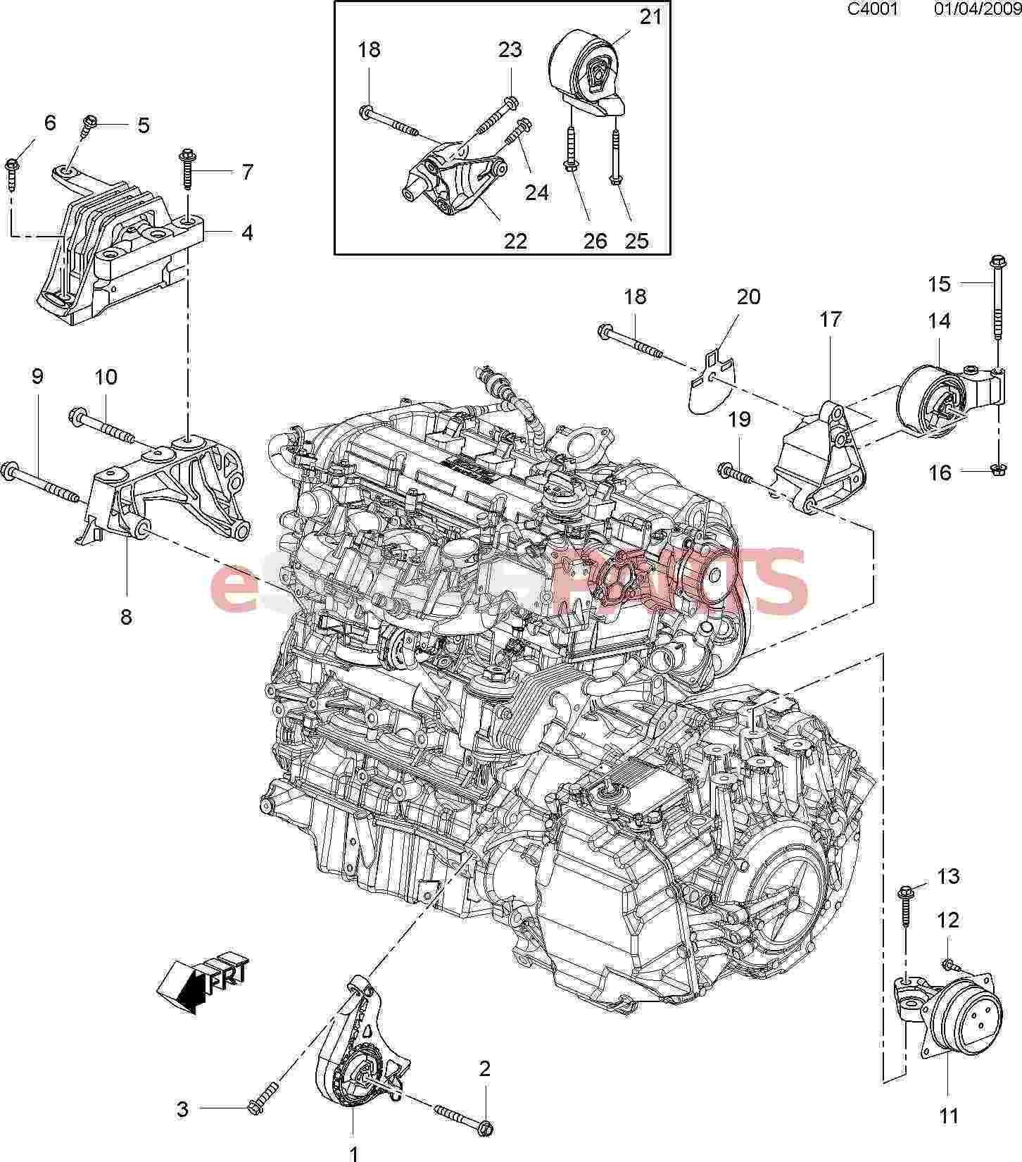
In this section, we will explore the essential components that make up the structure of an electronic device. These elements work together to ensure functionality and efficiency, each playing a key role in the overall performance. Gaining a comprehensive understanding of these components helps users troubleshoot issues and better appreciate how each part contributes to the system’s operation.
Key components often include power units, interface connectors, and internal circuitry that support communication between various functions. Recognizing their role and placement allows users to identify potential malfunctions or areas for improvement when repairs are necessary. By understanding these building blocks, individuals can enhance their experience and ensure long-lasting use.
Key Components of Insignia Products
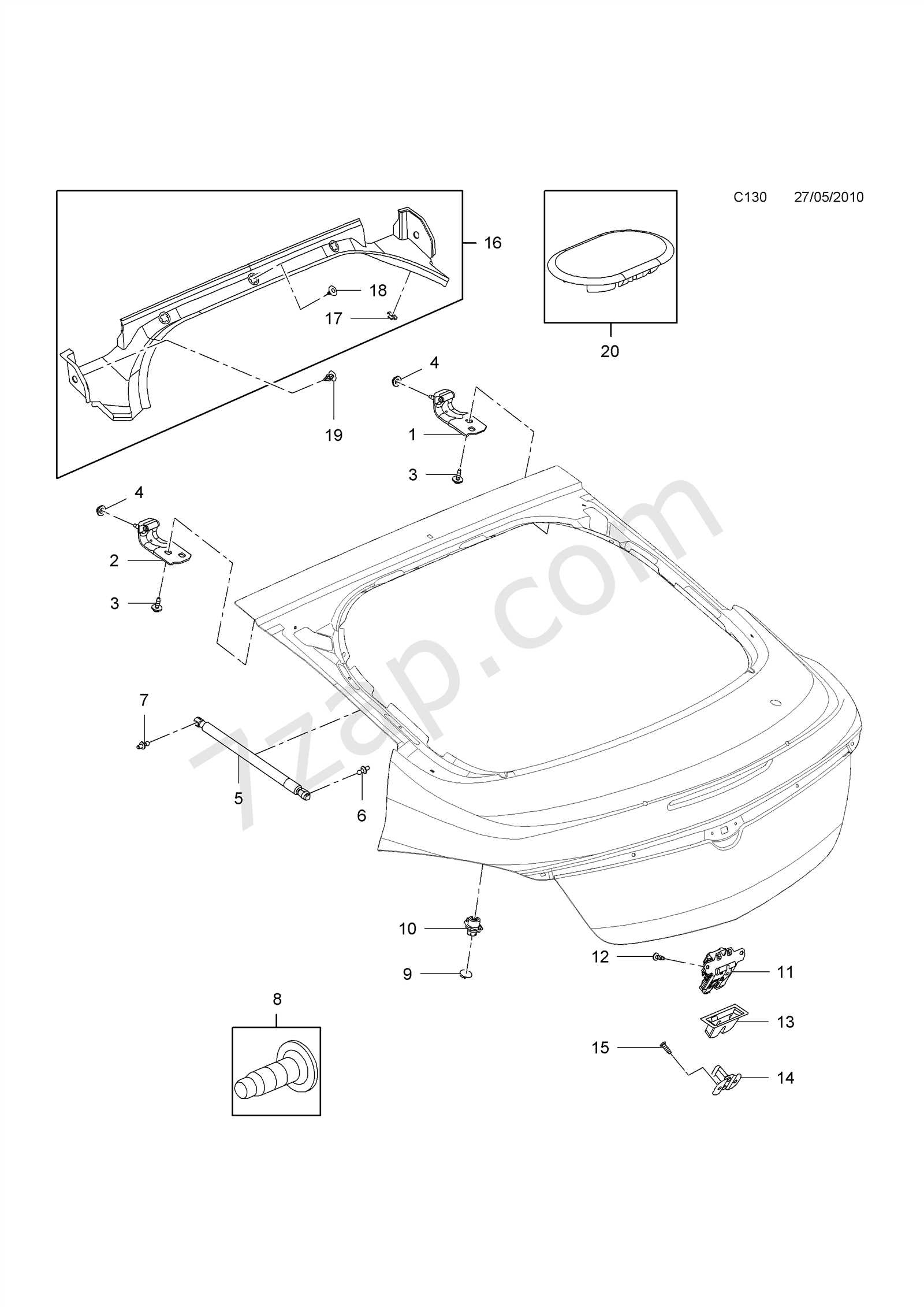
Understanding the core elements of any product is essential for both maintenance and enhancement. These components serve as the building blocks that ensure optimal functionality, performance, and reliability. By breaking down the major features and their roles, users can gain a better insight into how various systems interact and contribute to the overall user experience.
| Component | Function |
|---|---|
| Power Supply | Provides the necessary energy for the operation of the device, ensuring stable and continuous performance. |
| Display Screen | Visual interface for user interaction, displaying relevant data, settings, and content. |
| Control Panel | Allows users to adjust settings, control the functionality, and interact with the product’s system. |
| Connectivity Ports | Facilitate communication between the device and external equipment, supporting various data transfers and peripheral connections. |
| Audio System | Delivers sound output, essential for multimedia and communication functions, enhancing the user experience. |
| Internal Wiring | Ensures proper electrical connections between components, maintaining the flow of power and data throughout the device. |
How to Identify Insignia Parts
When working with any device, knowing how to recognize individual components is essential for both troubleshooting and repairs. This process involves understanding the unique identifiers for each element, which can often be located on the device itself or in accompanying documentation.
To effectively identify these components, follow these general steps:
- Examine the device for labels or tags that list component numbers or serial identifiers.
- Refer to the user manual or technical specifications for descriptions of each part’s function and location.
- Use online resources or manufacturer support tools to match component numbers with visual references.
Additionally, visual cues play a significant role. Identifying shapes, sizes, and connection points can help you match the component to its corresponding number. In some cases, even subtle markings can guide you to the right identification.
- Look for distinguishing features like unique connectors or mounting points that correspond to specific modules.
- Pay attention to the material used, as certain types of components are made from distinct substances or finishes.
By following these guidelines and taking a methodical approach, identifying the necessary parts becomes a manageable and efficient task.
Visual Guide for Component Recognition
In this section, we will explore various methods to identify and understand the components of a device. Recognizing individual elements and understanding their placement within the system can greatly enhance your troubleshooting and repair skills. Whether you’re assembling, disassembling, or repairing, knowing what each part looks like is essential for effective handling and problem-solving.
Key Features to Look For
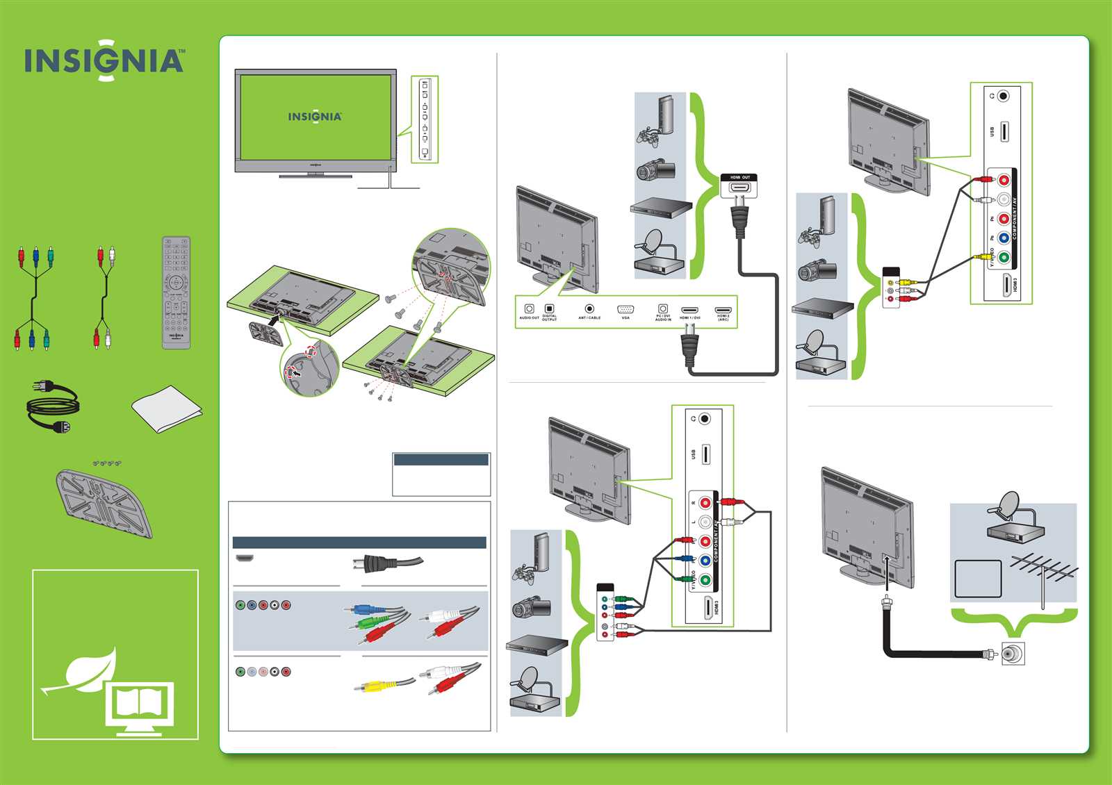
Each component in a device serves a specific purpose and is often marked with distinctive features that make it easier to recognize. Size, shape, and color can give immediate clues about a part’s function, while additional markings like numbers or letters often provide more detailed information about the component’s specifications.
How to Approach Identification
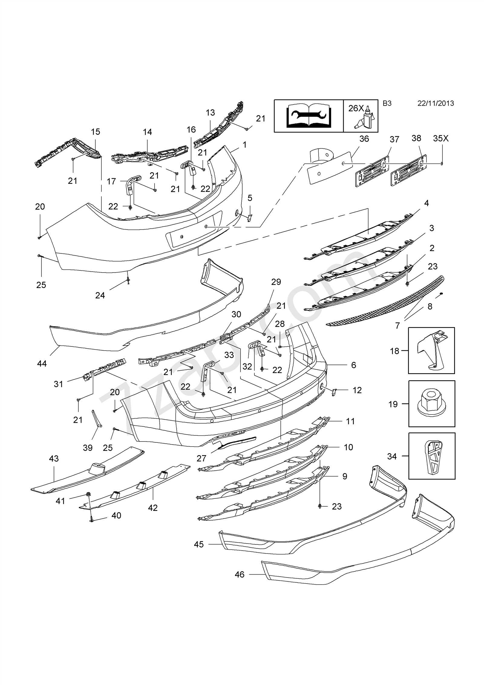
Start by focusing on the most obvious aspects of the components: their physical attributes and placement within the structure. Once identified, understanding how these parts connect to the overall system will help you gain a deeper knowledge of their functionality. Pay close attention to connections, polarity markings, and any symbols that might suggest their role.
Common Issues with Insignia Parts
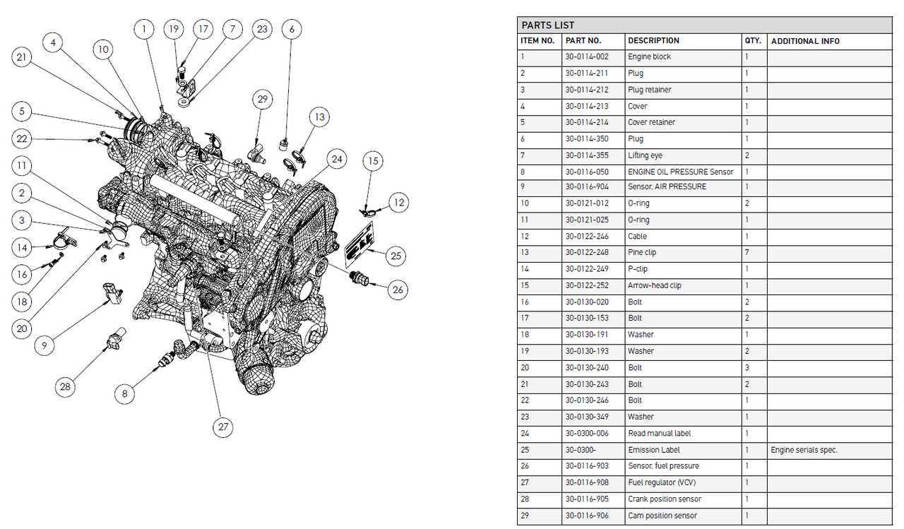
Devices often face various problems over time due to wear and tear, faulty components, or poor manufacturing. It is essential to understand some of the typical challenges that may arise, as these can affect functionality and performance. These issues may vary depending on the type of device, but there are several recurring problems worth noting.
- Connectivity Problems – Wires or connectors may become loose, causing malfunction or intermittent issues.
- Overheating – Inadequate ventilation or poor quality of certain internal components can lead to temperature build-up, resulting in system shutdowns or reduced efficiency.
- Unresponsive Controls – Buttons or touch interfaces may become nonfunctional due to worn-out connections or internal damage.
- Power Failures – Faulty power supply units or broken connectors can cause a complete failure of the device, leaving it unable to start up.
- Audio or Visual Distortions – Problems with internal circuitry may lead to issues with sound clarity or display quality.
Proper maintenance and regular inspection can help prevent many of these common challenges. Understanding how to recognize early signs of trouble can ensure that issues are resolved quickly before they escalate.
Identifying Faulty Components in Devices
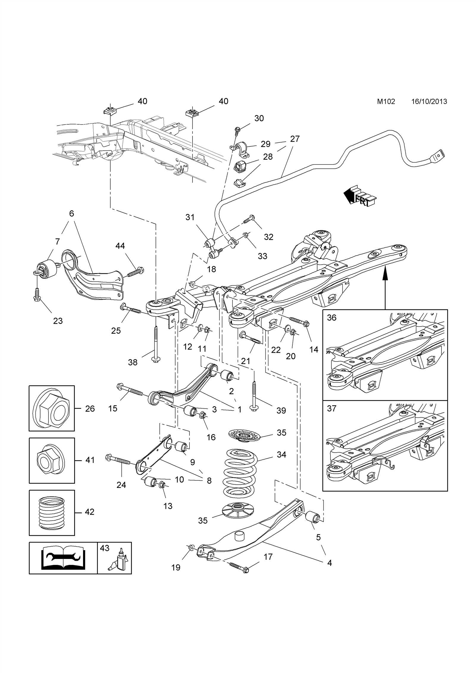
When a device stops functioning as expected, pinpointing the exact cause of the malfunction is crucial. Often, the issue lies with one or more internal components. By carefully examining the structure and function of the various elements, one can effectively identify the source of the problem. Understanding how each part contributes to the overall operation will help in troubleshooting and repair tasks.
Common Signs of Malfunction
- Unusual noises or vibrations during operation
- Complete loss of power or intermittent shutdowns
- Failure to respond to controls or commands
- Visible physical damage, such as cracks or burn marks
Steps to Diagnose Defective Elements
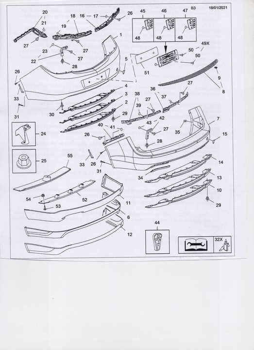
- Start by checking the power supply for any interruptions or inconsistencies.
- Examine the connections between internal circuits for loose wires or corroded contacts.
- Inspect individual components like capacitors, resistors, and chips for any signs of wear or overheating.
- Use testing tools like multimeters to measure voltage, resistance, and continuity across suspect parts.
Insignia Parts Assembly and Functionality
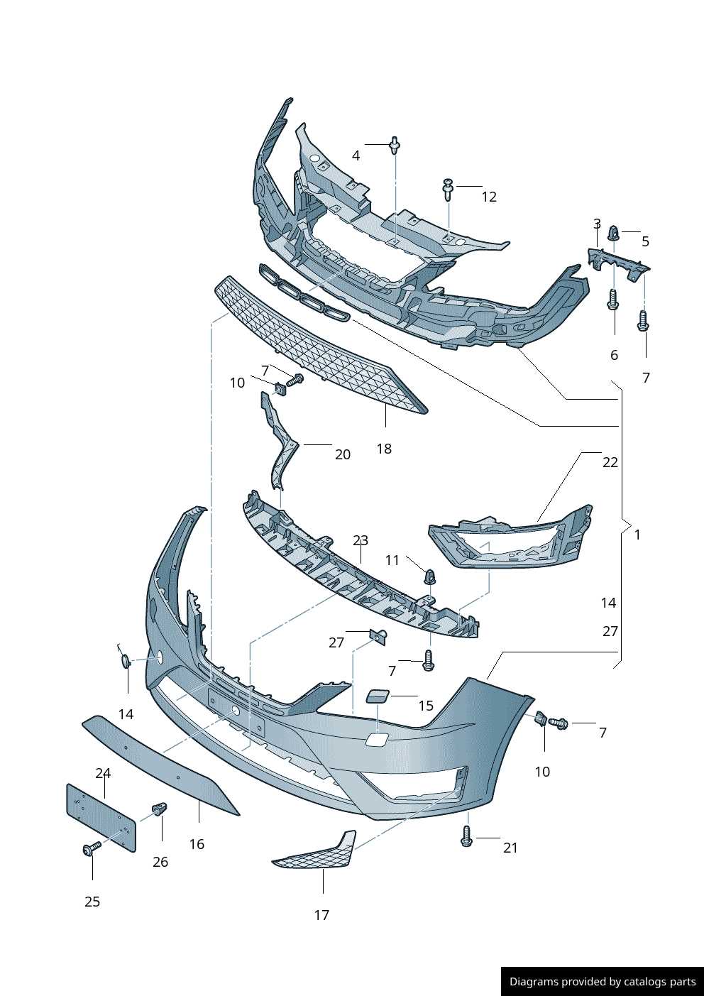
Understanding the structure and roles of various components within a device is essential for both maintenance and optimal performance. Each element, when combined, creates a cohesive system that operates seamlessly, contributing to the overall functionality. These interconnected units work together to ensure that the device performs its intended tasks efficiently and reliably.
Component arrangement is critical, as it determines how energy, data, and signals flow through the system. Proper alignment ensures that each part interacts with others in the most effective way possible, preventing issues like signal loss or mechanical failure. Each unit plays a specific role, whether it’s for power distribution, signal processing, or physical support, all of which are necessary for smooth operation.
When assembling the various elements, careful attention must be paid to how each part is secured and connected. This is not only important for ensuring proper function but also for maintaining durability and longevity of the entire assembly. Small adjustments or improper placements can result in degraded performance or even permanent damage over time.
How Each Piece Fits Together
Understanding how various components come together is essential for assembling and maintaining complex systems. Each element plays a crucial role, ensuring the overall functionality is seamless. The design of these systems allows every individual part to contribute to the larger purpose, enhancing efficiency and reliability. This section explores how these elements interact, working in harmony to create a fully operational whole.
The Interconnection of Components
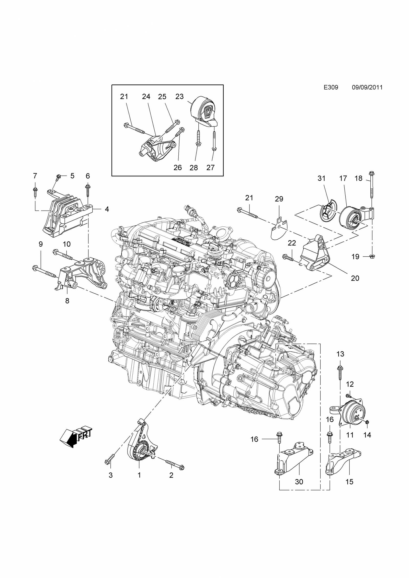
Each segment is strategically positioned to perform specific tasks, often connecting with others to form a cohesive structure. The alignment and integration of these pieces are vital for the system’s performance. Minor misalignments can result in significant issues, emphasizing the importance of precision during assembly.
Maintaining the Integrity of the Whole
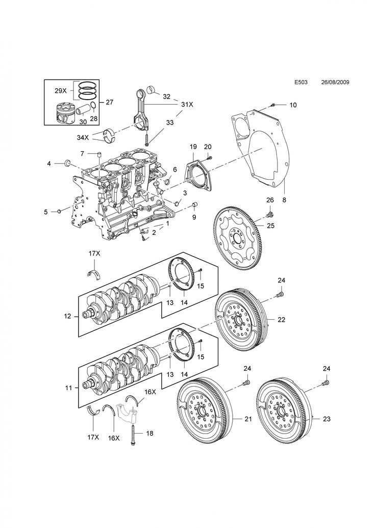
For continued optimal performance, the interaction between components must be maintained. Regular checks and proper care ensure that each piece continues to fulfill its role effectively. Even small adjustments can make a significant difference, highlighting the importance of understanding how each part contributes to the system’s integrity.
Replacing Insignia Parts Safely
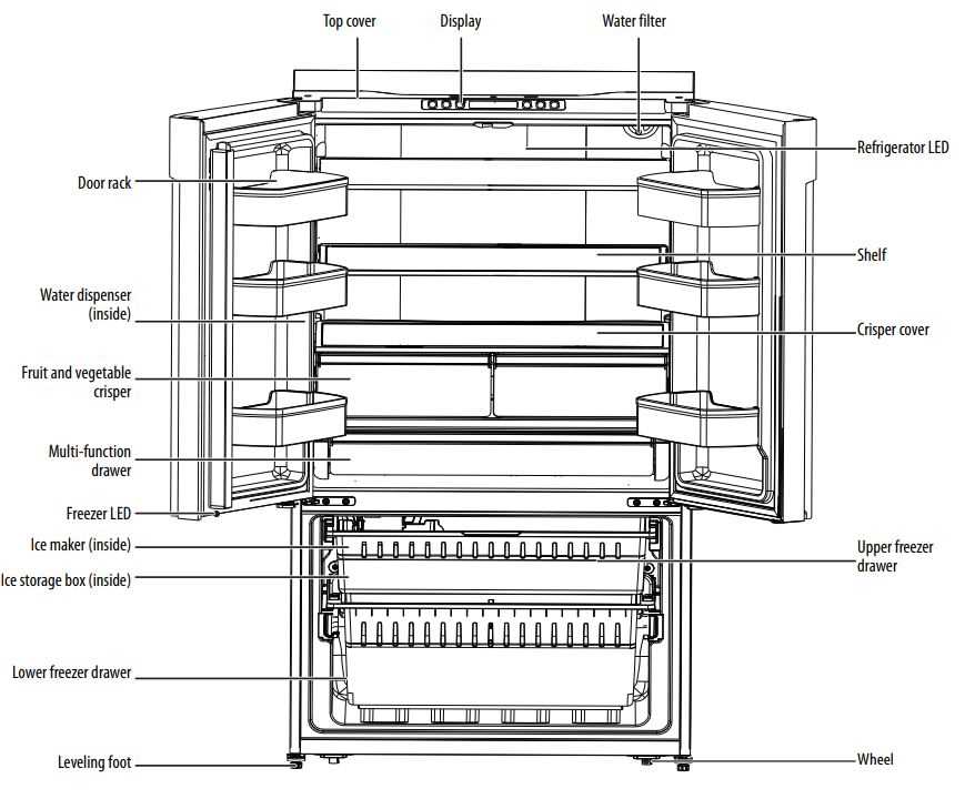
When it comes to handling the replacement of various components in your device, it’s crucial to prioritize safety and precision. Ensuring the correct steps are followed helps avoid damage and ensures the longevity of the equipment. Proper understanding of assembly and disassembly procedures is vital for any repair or upgrade task.
Preparation and Precautions
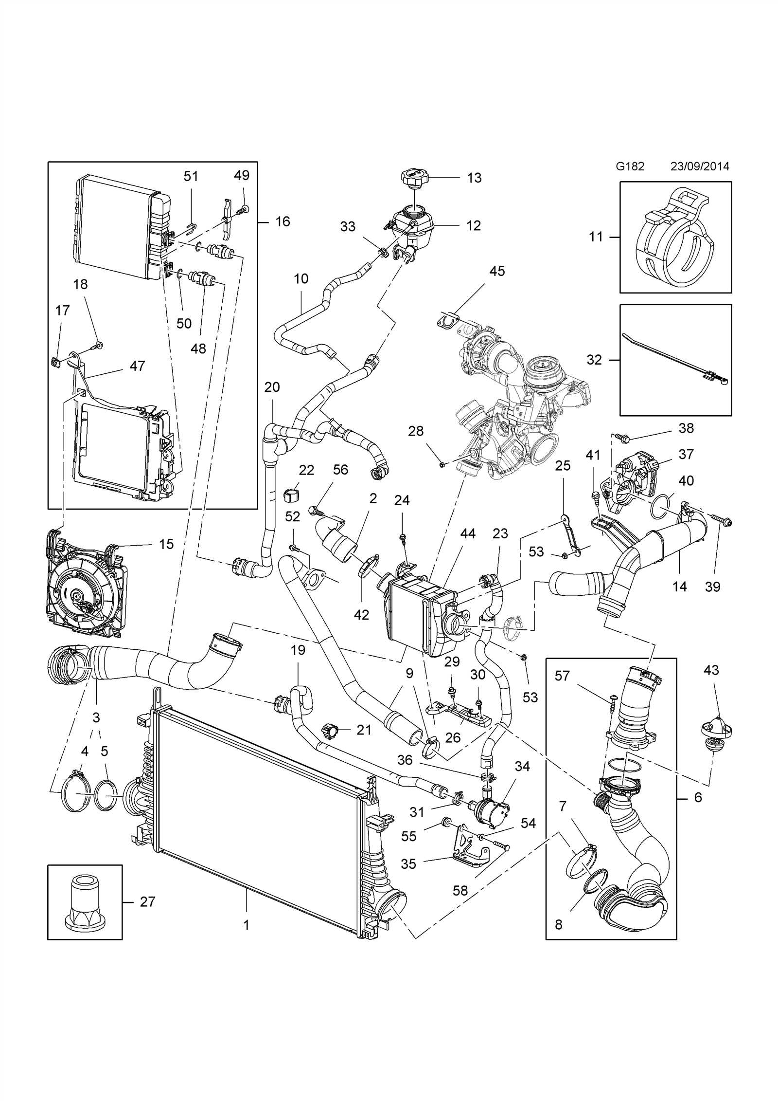
Before starting any replacement task, make sure to take the following steps:
- Disconnect the device from all power sources to avoid electrical hazards.
- Gather the necessary tools and spare components for a smooth process.
- Wear protective gear, such as gloves or safety glasses, to prevent injuries.
- Ensure a clean, well-lit workspace to minimize the chances of losing small components.
Step-by-Step Process
Follow these guidelines for a safe and efficient replacement:
- Carefully remove the old component without damaging surrounding parts.
- Inspect the new part for any visible defects before installation.
- Align the new component accurately to avoid misalignment or additional damage.
- Secure the component with the appropriate fasteners and tools, avoiding over-tightening.
- Test the device thoroughly to ensure proper function before reassembly.
Steps for Proper Component Replacement
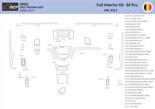
When performing maintenance or repair on a device, it’s essential to follow a clear process to ensure that each element is correctly replaced and functions optimally. Understanding the structure of the system and identifying the necessary components are critical first steps. Proper handling and installation of new parts ensure both longevity and efficiency in the repaired unit.
Begin by turning off and unplugging the device to avoid any electrical hazards. Then, carefully assess the issue to determine which components need to be replaced. Once identified, ensure you have the correct replacement parts that match the specifications required. Next, use appropriate tools to disassemble the unit safely, keeping track of any screws or fasteners that might be needed later. During the removal of old components, take care not to damage surrounding parts, as this can lead to additional repairs.
Once the damaged parts are removed, install the new components with precision. Ensure they are securely connected and properly aligned. After replacing the parts, reassemble the device carefully, ensuring that all parts fit back into place. Finally, test the device to confirm that it operates as expected, ensuring the new components are functioning correctly and no further issues exist.