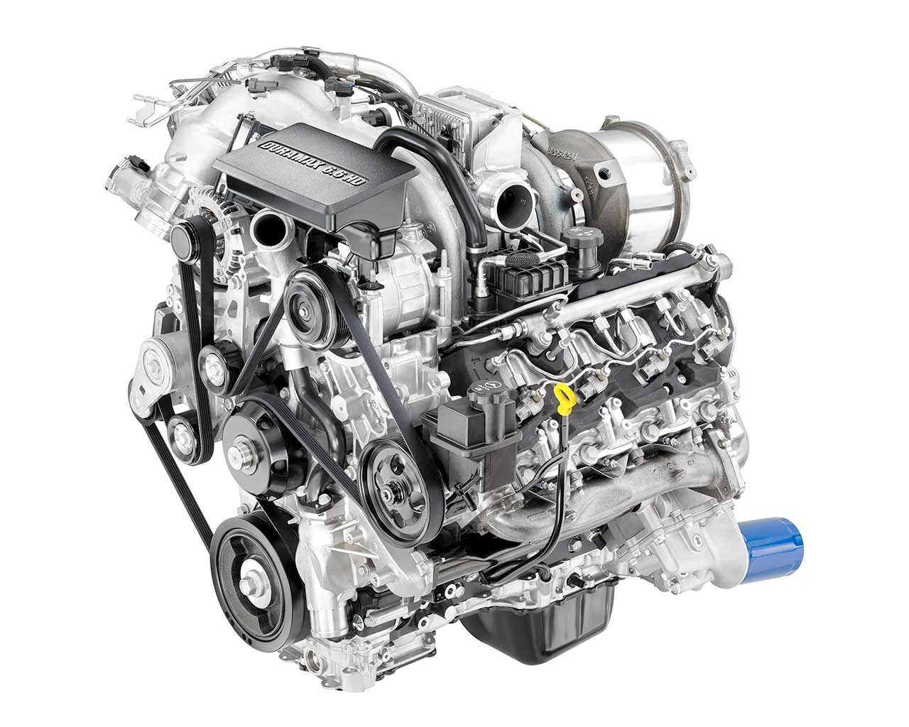
The inner workings of a complex mechanical system can be daunting, especially when it comes to identifying the various elements that contribute to its functionality. Gaining clarity on the arrangement and the roles of different components within the system is crucial for effective maintenance and troubleshooting. This section delves into the essential elements that make up such intricate machinery and explains how they come together in a coherent structure.
By exploring the layout of key elements, you will gain insight into the vital connections and functions that ensure optimal performance. Whether you are looking to enhance your technical knowledge or need practical guidance for repairs, this detailed overview offers a clear understanding of how everything fits and operates in unison.
In the following sections, we will break down the core structures, providing a closer look at each part’s role, its connections to surrounding components, and the significance of proper alignment. This information is essential for those who want to ensure their machinery runs smoothly and efficiently.
Overview of the 6.6 Duramax Engine Layout
The power unit in question is renowned for its durability and efficiency, making it a popular choice in various applications. Its structure is thoughtfully designed, with key components strategically positioned to enhance both performance and ease of maintenance. This section offers a closer look at the arrangement of these crucial elements, helping to understand how each component contributes to the overall functionality.
Main Structural Components
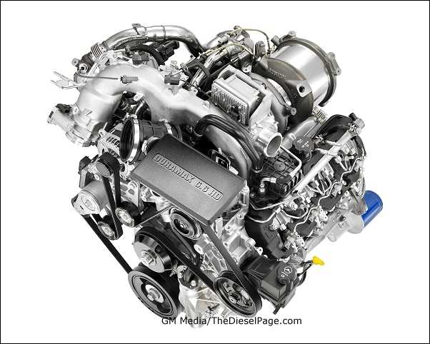
The heart of the system includes a block that serves as the foundation for multiple vital parts. These elements work in harmony to ensure smooth operation and power delivery. The layout also includes essential systems responsible for cooling, fuel management, and exhaust, all arranged to optimize space and functionality.
Connections and Supporting Elements
Supporting components play a crucial role in maintaining the reliability of the entire unit. Various conduits, sensors, and control mechanisms are integrated seamlessly into the design, ensuring efficient communication between different parts. The positioning of these connections contributes to the overall performance and safety of the system.
Main Components of the 6.6 Duramax System
This section outlines the key elements within a complex mechanical assembly, focusing on crucial units that work together to ensure smooth operation and reliability. Each part plays a unique role in managing processes such as power generation, fluid dynamics, and control systems. Below, we will explore the primary structures and their contributions to overall functionality.
Fuel Delivery Mechanism
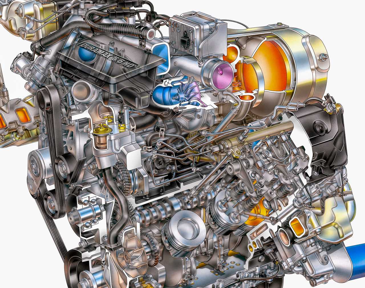
The fuel supply system is integral to the unit’s performance, efficiently managing the flow of fuel to ensure optimal combustion. Key elements in this mechanism include:
- High-pressure pump
- Fuel injectors
- Regulator valves
These components work together to maintain precise fuel distribution, ensuring energy efficiency and minimizing waste.
Cooling and Lubrication System
Maintaining appropriate temperature and reducing friction are essential for the longevity of the assembly. The cooling and lubrication setup involves several critical parts, including:
- Radiator
- Oil pump
Fuel Injection and Distribution Setup
Effective fuel injection and distribution are critical to achieving optimal performance and efficiency in modern systems. The setup ensures precise delivery of fuel, allowing for controlled combustion, which enhances power output and reduces emissions.
The arrangement typically includes multiple components that work together to deliver fuel from the tank to the combustion area. These elements coordinate to regulate pressure, timing, and volume of fuel for efficient operation.
- Fuel Delivery Mechanism: This component ensures a consistent flow of fuel is supplied to the injectors, maintaining the correct pressure throughout the process.
- Injection Nozzles: Precisely calibrated nozzles are responsible for dispersing the fuel into the combustion chamber in fine, controlled patterns.
- Distribution Control: Various sensors and control units monitor conditions, adjusting the flow of fuel based on real-time feedback to maintain balance across all injection points.
Understanding how these components work in harmony is essential for maintaining system reliability and
Cooling Mechanism and Its Functionality
The cooling system plays a vital role in maintaining the optimal temperature of a machine’s core components, ensuring that they do not overheat during operation. This process involves a series of interconnected parts designed to regulate heat dissipation, safeguarding the overall performance and longevity of the system.
At the heart of this mechanism is a fluid-based method that circulates coolant to absorb excessive warmth and transports it to a specialized section where heat is effectively released into the surrounding air. This constant circulation prevents any build-up of excessive temperature, which could lead to malfunction or permanent damage to internal components.
Another crucial aspect of this setup includes sensors that monitor temperature levels and activate additional cooling measures when needed. These responsive actions maintain balance in heat levels, ensuring that the equipment runs efficiently without interruptions. Regular maintenance of this system is essential to ensure its functionality and to prevent the risk of overheating or wear and tear over time.
Turbocharger and Air Intake Pathways

The turbocharger and air intake system play a vital role in boosting performance and optimizing airflow for increased power. By effectively compressing air and delivering it to the combustion area, this system enhances efficiency and overall functionality, contributing to the vehicle’s power output.
How the Turbocharger Works
A turbocharger operates by using exhaust gases to spin a turbine, which in turn compresses incoming air. This compressed air is then forced into the intake manifold, allowing for more oxygen to mix with the fuel. The result is a significant increase in power without additional fuel consumption.
- Turbine powered by exhaust gases
- Compressor increases air pressure
- Enhanced air-fuel mixture for better combustion
Key Components of the Air Intake
Exhaust System Structure and Flow
The exhaust system is a crucial component in any vehicle, ensuring efficient gas expulsion and reducing emissions. Its layout consists of multiple elements working together to channel exhaust gases away from the vehicle’s internal systems, improving performance and reducing environmental impact. The configuration of these elements allows for smooth passage of gases, minimizing resistance and optimizing flow.
Below is an overview of the key sections within the exhaust structure:
| Section |
Function |
| Exhaust Manifold |
Collects gases from the combustion chambers and directs them into the system. |
| Catalytic Converter |
Reduces harmful emissions by converting toxic gases into less harmful substances. |
| Muffler |
Minimizes noise produced by the gases
Electrical Wiring and Sensor Connections
The electrical system in a vehicle involves a network of wires and sensors that work together to monitor and control various functions. These components play a critical role in ensuring the proper operation of the vehicle’s systems by sending and receiving signals to and from the control units. Proper wiring and sensor integration are essential for the accuracy of data and the reliability of the overall system.
Several key components are involved in the electrical connections, including:
- Sensors: Devices that monitor specific conditions, such as temperature, pressure, and speed, transmitting data to the vehicle’s control system.
- Wiring Harnesses: Bundles of wires that provide the necessary connections between the sensors and control units, allowing for the seamless flow of data and power.
- Connectors: Specialized parts that ensure secure and efficient links between different wiring sections, preventing any power loss or signal interference.
The correct configuration and maintenance of these components are crucial to avoid electrical malfunctions. Troubleshooting issues in the wiring system often involves checking the continuity of connections, verifying sensor outputs, and ensuring all connectors are properly engaged.
Key areas to focus on for proper wiring and sensor installation include:
- Proper insulation and protection of wires to prevent short circuits and damage.
- Ensuring that connectors are tightly secured and free of corrosion to maintain optimal signal quality.
- Regular inspections to identify any wear or damage to the wiring system that could lead to malfunction.
Incorporating these practices ensures a more efficient and reliable electrical system, contributing to the smooth operation of the vehicle’s functions.
Lubrication Circuit and Oil Flow
The lubrication system is critical for ensuring smooth operation by minimizing friction between moving components. It delivers oil to various parts to reduce wear and prevent overheating. Understanding the flow and routing of this fluid helps ensure efficient performance and longevity of the system.
Oil Delivery and Pathways
In a typical lubrication system, oil is pumped from the reservoir and circulated through several key components. The system is designed to target areas that experience the most friction, ensuring that each part is adequately lubricated throughout operation.
- Oil pump: Pumps the oil from the reservoir to the various engine parts.
- Oil filter: Removes contaminants from the oil before it circulates through the system.
- Oil galleries: Pathways through which oil travels to reach critical components.
Oil Flow Regulation
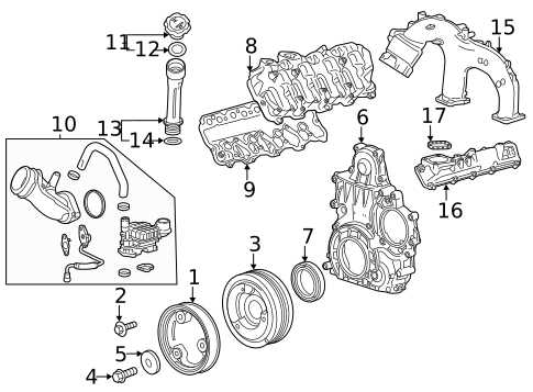
To optimize performance, the flow of oil is carefully regulated. The system typically includes pressure relief valves and temperature sensors to ensure the oil is at the correct pressure and temperature for efficient lubrication.
- Pressure relief valve: Controls oil pressure to prevent excessive buildup.
- Thermostatic valve: Regulates oil temperature by directing flow based on temperature variations.
Transmission Interface with the 6.6 Duramax
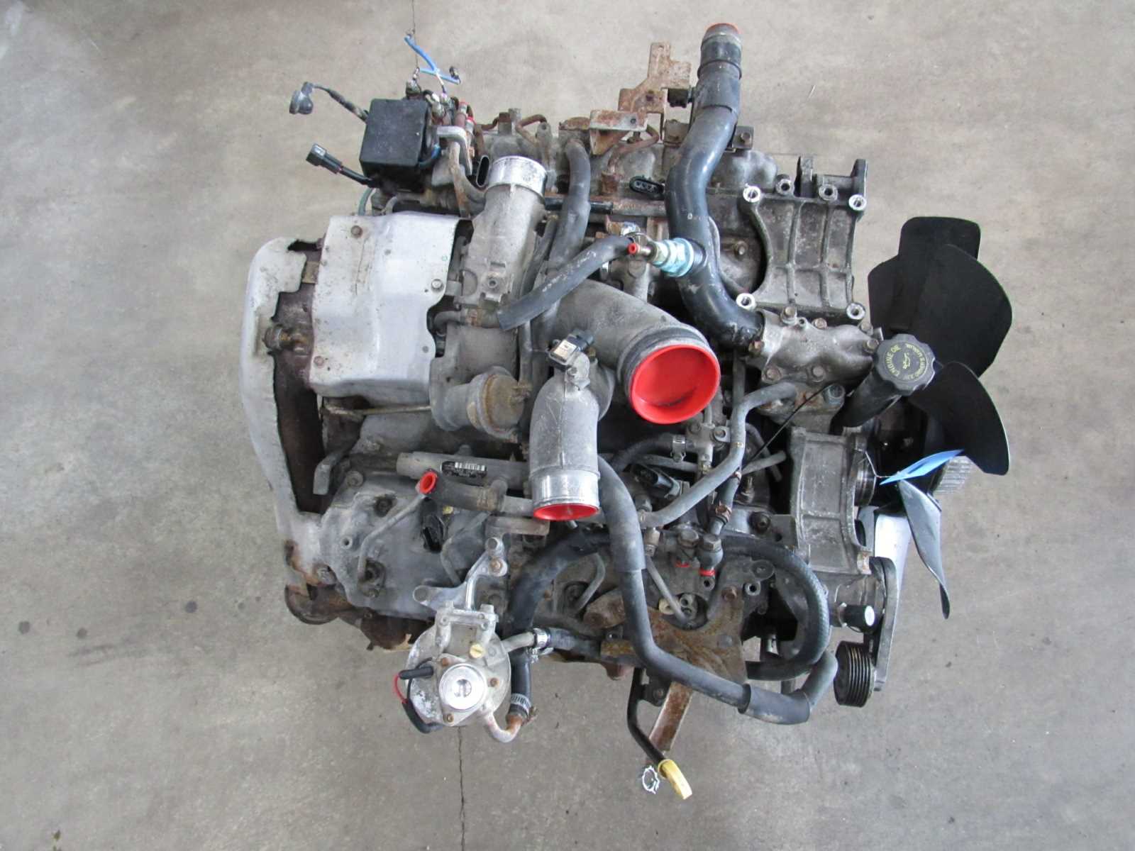
The interaction between the transmission system and the power unit is crucial for optimal performance and smooth operation of the vehicle. This connection ensures that the power generated by the unit is efficiently transmitted to the wheels, providing the necessary torque and speed for driving. Proper coordination between these components is essential for maintaining reliability and minimizing wear over time.
Several components play a significant role in facilitating this interface:
- Torque Converter: Acts as a fluid coupling between the engine and the transmission, allowing for smooth power transfer at varying engine speeds.
- Transmission Valve Body: Controls fluid flow within the transmission to engage the appropriate gear ratios depending on driving conditions.
- Flywheel: Provides rotational mass and helps to smooth out power delivery during shifts, preventing jerky movements.
- Shifter Linkage: Mechanically or electronically connects the driver’s input to the transmission, allowing gear selection.
- Input Shaft: Transfers rotational energy from the power unit to the transmission’s internal components.
The smooth engagement of these components ensures seamless shifting, improved fuel efficiency, and enhanced driving experience. Regular maintenance and checks of the transmission system help preserve this crucial interaction, leading to a longer-lasting drivetrain.
|


