Toro Gas Trimmer Parts Diagram and Component Guide

In toro

toro gas trimmer parts diagram

Understanding the internal layout and essential elements of outdoor maintenance devices can significantly enhance the efficiency of their upkeep and repair. This guide offers a detailed look at the key mechanisms involved in such tools, providing clarity for both routine maintenance and occasional fixes.

By exploring the various components within these landscaping devices, users can better grasp the overall functionality and pinpoint any issues that may arise over time. Whether you’re performing regular upkeep or troubleshooting a malfunction, familiarizing yourself with the intricate connections and configurations is vital for smooth operation.

This section will walk through the primary assemblies, offering insights into the most common replacements and adjustments needed to keep your equipment running smoothly. Understanding these details can help you maintain optimal performance and prolong the lifespan of your tool.

Toro Gas Trimmer Overview

Outdoor maintenance tools are essential for keeping landscapes neat and tidy. These devices are specifically designed to handle dense foliage and various types of vegetation. They offer users efficiency and ease of use when trimming areas that may be hard to reach with larger equipment.

The structure and features of these yard tools allow for precision, while also providing a powerful performance. From cutting through thick grass to managing delicate edges, they serve a wide range of purposes. The following table outlines some of the key attributes that contribute to their effectiveness:

Understanding the Components of Toro Gas Trimmers

toro gas trimmer parts diagram

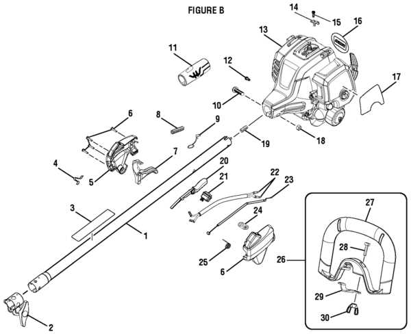
When working with powered cutting tools, it’s essential to become familiar with the various mechanisms that allow the machine to function efficiently. Each part plays a critical role in ensuring smooth operation, from the engine down to the smallest detail. Proper knowledge of these elements can aid in maintenance, troubleshooting, and overall use.

Power Unit: This section contains the main driving force behind the tool, where fuel or energy is converted into the mechanical action needed for operation. It’s essential to ensure this area is kept in good condition for optimal performance.

Cutting Mechanism: The sharp, rotating section responsible for trimming vegetation. Regular cleaning and sharpening are key to keeping it functioning efficiently, ensuring clean and precise cuts with each use.

Control Handles: These parts allow the user to guide and operate the equipment safely and effectively. Designed with ergonomics in mind, they ensure that the tool can be comfortably maneuvered for extended periods.

Understanding how each part contributes to the overall performance can he

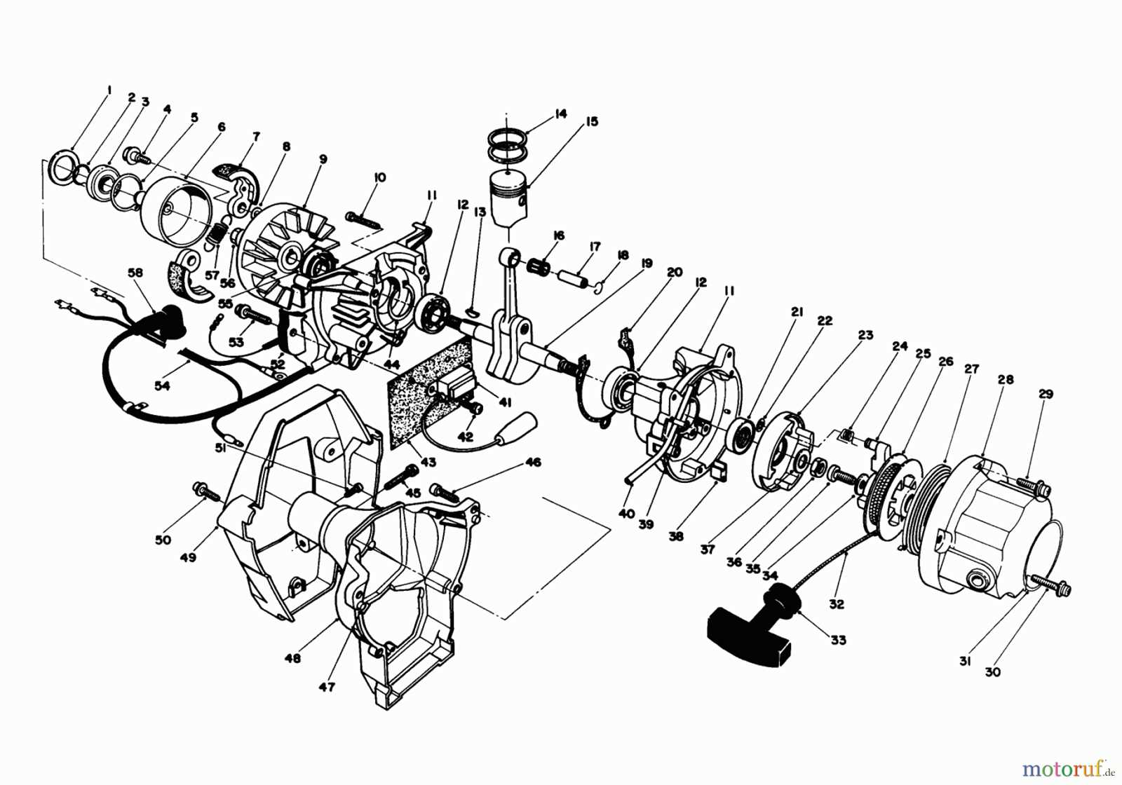
Diagram for Internal Engine Parts

toro gas trimmer parts diagram

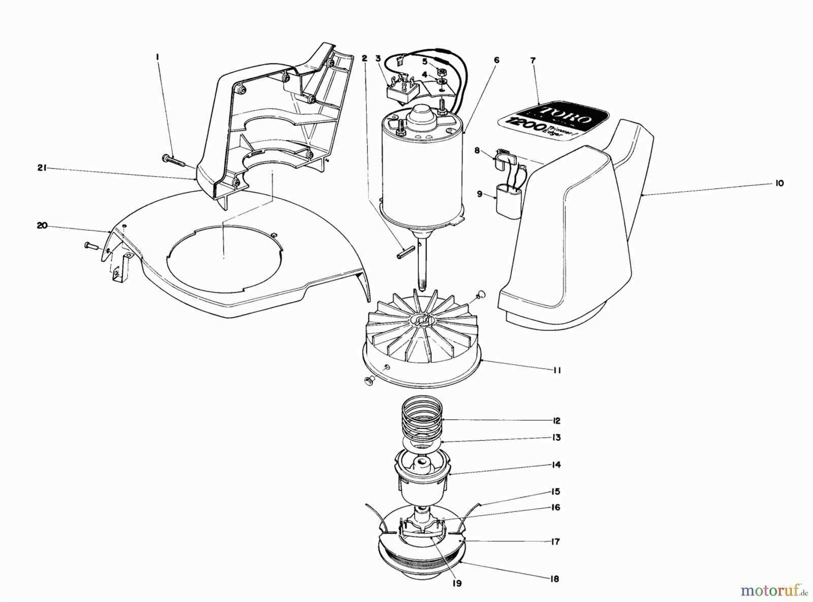
This section focuses on the arrangement and components within a typical small engine. Understanding how internal mechanisms are organized is essential for efficient operation and maintenance. The internal structure includes various interconnected elements that work together to ensure smooth performance.

Key Components of the Engine

toro gas trimmer parts diagram

  • Piston: The central moving element that generates the necessary pressure for movement.
  • Cylinder: A housing unit where the piston moves, controlling the combustion process.
  • Crankshaft: Converts the piston’s linear movement into rotational force.
  • Connecting Rod: Links the piston to the crankshaft, enabling motion transfer.

How the Engine Works

toro gas trimmer parts diagram

  1. The piston moves within the cylinder, creating pressure as the fuel mixture ignites.
  2. The connecting rod transfers this motion to the crankshaft.

    Handle and Control Assembly Breakdown

    toro gas trimmer parts diagram

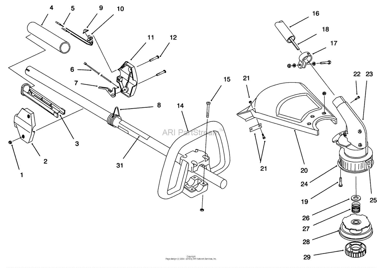
    The handle and control system plays a vital role in ensuring smooth operation and comfort during use. It allows for efficient maneuvering and precise control, ensuring the user can adjust settings easily while maintaining a firm grip. Below is a detailed breakdown of the individual components that make up this essential assembly.

    Main Handle Structure

    toro gas trimmer parts diagram

    The main handle provides stability and ergonomic comfort during prolonged use. It is often designed with cushioned grips and may include adjustable features to suit different hand sizes. This section covers the structure that connects to the shaft and supports the control mechanisms.

    • Ergonomic grip for reduced hand strain
    • Adjustable handle height or angle
    • Durable material for long-lasting performance

    Control Levers and Switches

    toro gas trimmer parts diagram

    The control area is equipped with various levers and switches that allow for seamless operation. These controls are designed for quick access and reliable performance, ensuring that adjustments can be made with minimal effort.

    1. Throttle control

      Fuel System Parts and Their Placement

      toro gas trimmer parts diagram

      The fuel delivery system is crucial for ensuring smooth operation and efficiency. Understanding the components involved in this system and how they are arranged helps maintain optimal performance. Each element plays a specific role in delivering the necessary fuel mixture to the engine.

      • Fuel Tank: This is where the fuel is stored before it flows into the engine. Positioned near the base, it is designed for easy access during refueling.
      • Fuel Lines: Tubes that transport fuel from the storage unit to the engine. They are typically flexible and run along the frame to connect different components efficiently.
      • Fuel Filter: Installed along the fuel line, this device ensures that impurities are removed before the fuel reaches the engine. It is often placed between the tank and the carburetor.
      • Carburetor: A key part that mixes fuel with air in the correct ratio for combustion. It is usually mounted near the engine, close to the intake system.
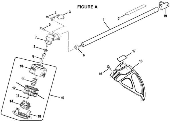
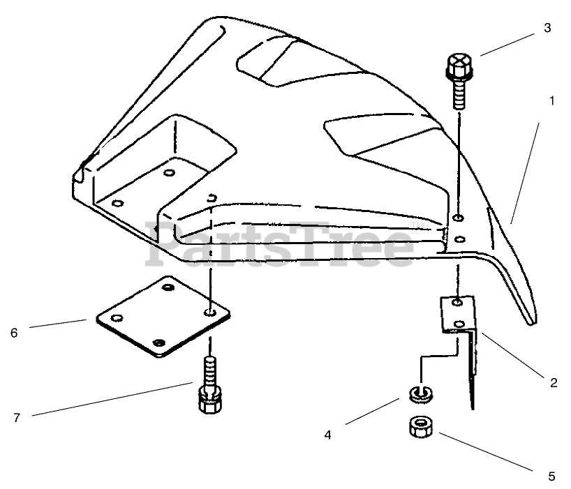
      • Blade Guard and Trimmer Head Structure

        toro gas trimmer parts diagram

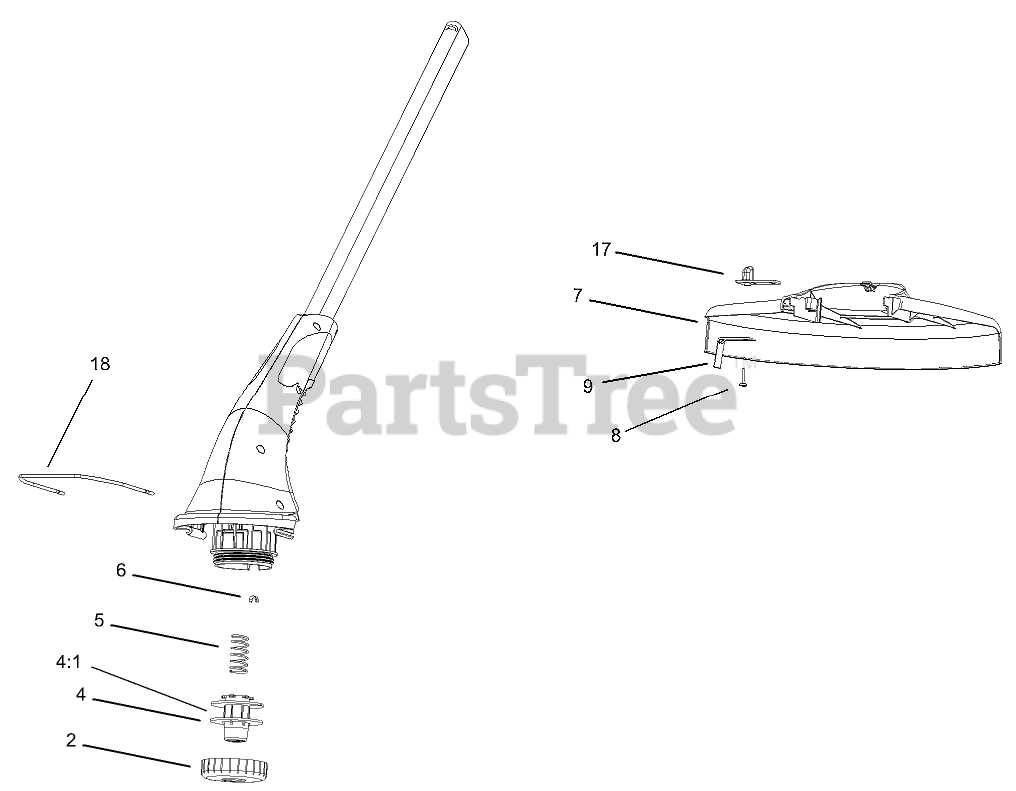
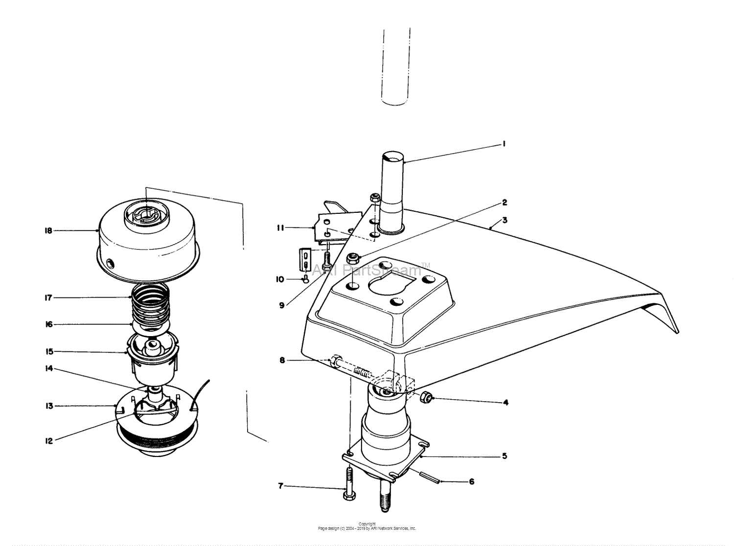
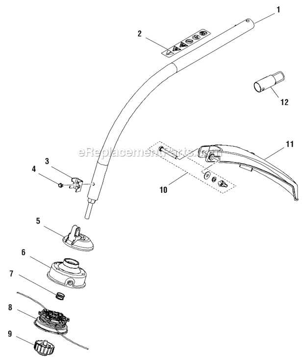
        The blade guard and the cutting head play a crucial role in the functionality of lawn maintenance equipment. These components not only enhance the efficiency of the tool but also ensure safety during operation. Understanding their structure and relationship is essential for effective use and maintenance.

        The blade guard serves multiple purposes:

        • Protects the user from accidental contact with the cutting edge.
        • Helps direct grass clippings and debris away from the operator.
        • Ensures the longevity of the cutting blade by shielding it from damage.

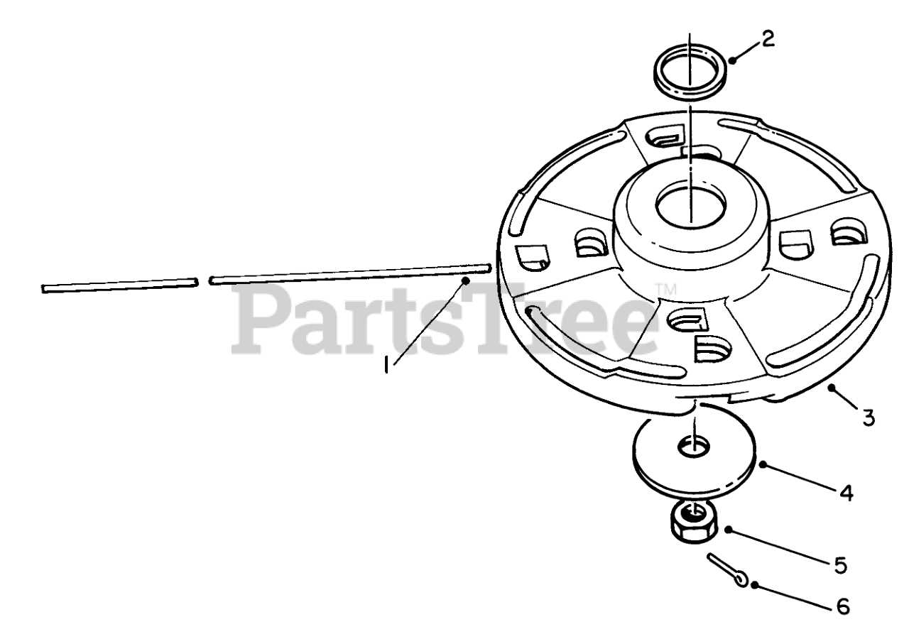
        On the other hand, the cutting head is where the actual trimming action occurs. Its design typically includes the following elements:

        1. Cutting Mechanism: This can be a blade or line, depending on the type of tool.
        2. Attachment Points: These are crucial for securely connecting the cutting head to the motor unit.
        3. Adjustable Features: Some heads allow for height adjustments or angle changes for varied cutting needs.

        Both the guard and cutting head contribute to the overall effectiveness of the equipment, making them essential for any landscaping task. Proper understanding and maintenance of these components can lead to improved performance and safety during usage.

        How the Drive Shaft Assembly Works

        toro gas trimmer parts diagram

        The drive shaft assembly plays a crucial role in transferring power from the engine to the cutting mechanism of outdoor equipment. This assembly is designed to efficiently transmit torque while maintaining stability and performance during operation. Understanding its functionality can help users appreciate its importance in the overall performance of the machine.

        Key Components of the Drive Shaft Assembly

        toro gas trimmer parts diagram

        • Outer Shaft: The outer shaft encases the inner components and provides structural integrity.
        • Inner Shaft: This component rotates and carries the torque from the engine to the cutting head.
        • Couplers: Couplers connect the inner shaft to the engine and cutting head, ensuring smooth power transfer.
        • Bearings: Bearings reduce friction and support the rotating shafts, enhancing efficiency and longevity.

        Functionality of the Drive Shaft Assembly

        toro gas trimmer parts diagram

        The drive shaft assembly operates by converting rotational energy generated by the engine into linear motion that drives the cutting tool. As the engine runs, the outer shaft remains stationary while the inner shaft rotates rapidly. This rotation creates torque that is transmitted through the couplers to the cutting head, enabling effective trimming and cutting actions.

        Regular maintenance and inspection of the drive shaft assembly are essential for optimal performance. Users should check for wear and tear, ensuring all components are functioning correctly to prevent issues during operation.

        Maintenance Tips for Key Parts

        toro gas trimmer parts diagram

        Proper upkeep of essential components is crucial for ensuring optimal performance and longevity of outdoor power equipment. Regular maintenance not only enhances efficiency but also minimizes the risk of unexpected breakdowns. Below are some practical suggestions to help keep vital parts in top condition.

Feature Description
Cutting Mechanism Equipped with durable blades or strings that ensure consistent performance across different terrains.
Ergonomic Design Built with comfort in mind, reducing strain during prolonged use and allowing for better control.
Component Maintenance Tips
Air Filter Inspect and clean the air filter regularly to prevent debris buildup that can hinder airflow. Replace it if damaged or excessively dirty.
Spark Plug Check the spark plug for wear and replace it as necessary. Ensure that the gap is set to the manufacturer’s specifications for optimal ignition.
Fuel System Keep the fuel tank clean and free of contaminants. Use fresh fuel and consider adding a fuel stabilizer if the equipment will not be used for an extended period.
Cutting Head Examine the cutting head for wear and tear. Replace any damaged blades or lines to ensure efficient cutting performance.
Casing Regularly inspect the outer casing for cracks or damage. Clean it to remove dirt and debris, which can lead to overheating.

Troubleshooting Common Issues Using Diagrams
toro gas trimmer parts diagram

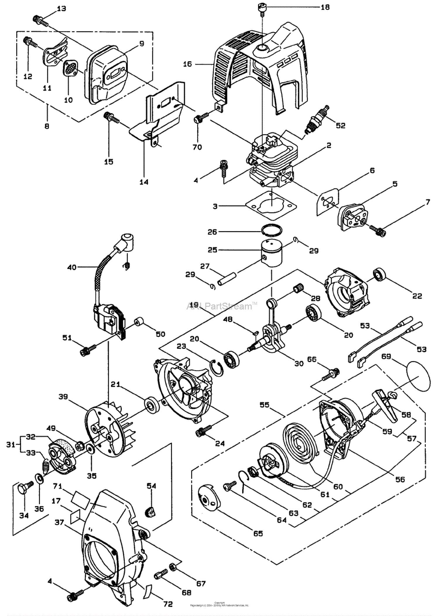
When facing operational challenges with outdoor power equipment, visual aids can be invaluable in identifying and resolving problems efficiently. Utilizing illustrations that depict various components and their functions allows users to pinpoint issues quickly and understand the interrelationships between parts.

Identifying Symptoms: Start by recognizing the specific symptoms your equipment is exhibiting. Common signs might include unusual noises, reduced performance, or failure to start. Having a clear illustration helps to correlate these symptoms with potential causes, allowing for a systematic approach to troubleshooting.

Step-by-Step Guidance: Diagrams often provide a step-by-step guide for maintenance and repairs. By following visual instructions, users can easily locate necessary components and understand how to access them for inspection or replacement. This method not only simplifies the process but also minimizes the risk of errors.

Common Problems and Solutions: Many issues can be traced back to specific components, such as filters, fuel lines, or ignition systems. By referring to a detailed illustration, users can quickly isolate these elements and follow recommended solutions. For instance, if starting difficulties are encountered, the diagram may highlight troubleshooting steps related to the fuel delivery system or spark plug condition.

Maintenance Best Practices: Regular upkeep is crucial for the longevity of any outdoor equipment. Visual aids can help outline essential maintenance tasks, such as cleaning, replacing worn parts, or lubricating moving components. By adhering to a visual maintenance schedule, users can prevent many common issues from arising in the first place.

In conclusion, leveraging visual resources enhances the troubleshooting process. It empowers users to diagnose problems accurately and implement effective solutions, ultimately leading to improved performance and reliability of outdoor power tools.