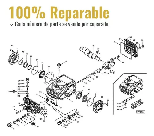
In the realm of fluid dynamics, a comprehensive grasp of the essential elements that contribute to efficient operation is crucial. This segment delves into the intricate world of machinery responsible for transporting liquids, focusing on the fundamental structures that play a vital role in their functionality. By dissecting these components, one can appreciate their significance in ensuring optimal performance and reliability.
Each mechanism comprises various segments, each serving a specific purpose. From the core assembly that facilitates movement to auxiliary features that enhance performance, understanding these intricacies enables a deeper insight into operational excellence. Moreover, a visual representation of these elements can greatly aid in grasping their interrelationships and overall impact on system efficacy.
As we explore these illustrations, emphasis will be placed on the arrangement and connections between individual pieces, highlighting how their design contributes to seamless operation. This knowledge not only assists in troubleshooting but also fosters a better appreciation for the engineering that underpins these complex systems.
Understanding Pump Components

In the realm of fluid movement systems, grasping the intricacies of each element is crucial for optimal performance. A thorough comprehension of these essentials not only enhances efficiency but also aids in troubleshooting and maintenance.
Every mechanism is composed of various elements, each playing a vital role in ensuring smooth operation. Key components such as the casing, impeller, and seal work in unison to facilitate the transfer of liquids from one location to another.
Recognizing the functionality of these individual parts allows for a deeper appreciation of how they interact under different conditions. This understanding is paramount for engineers and technicians striving for the ultimate reliability in their systems.
Importance of Diagrams in Maintenance
Visual representations play a crucial role in the upkeep of machinery and systems. They provide clarity and enhance understanding, making maintenance tasks more efficient and accurate.
- Facilitates quick identification of components
- Aids in troubleshooting issues effectively
- Enhances training for new technicians
- Supports proper reassembly after servicing
Utilizing these visual aids can ultimately reduce downtime and improve overall operational reliability.
Types of General Pump Systems
Understanding the various systems available is essential for efficient fluid movement in numerous applications. Each system is designed with specific characteristics to meet diverse operational requirements, enhancing performance and reliability.
Centrifugal Systems
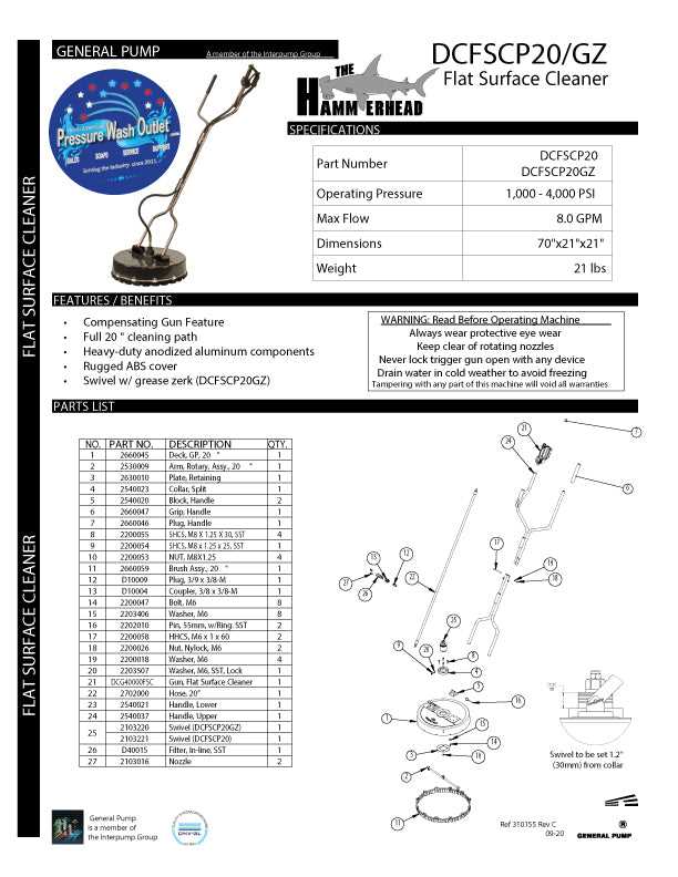
Centrifugal systems utilize rotational energy to propel fluids. This type excels in high-flow scenarios and is widely favored in industrial settings due to its efficiency and simplicity. Key advantages include minimal maintenance and the ability to handle a range of fluid types.
Positive Displacement Systems
Positive displacement systems operate by trapping a fixed amount of fluid and forcing it through the outlet. These systems are ideal for applications requiring high pressure and precise flow control. Applications often include hydraulic machinery and chemical processing, where consistent delivery is crucial.
Common Parts and Their Functions
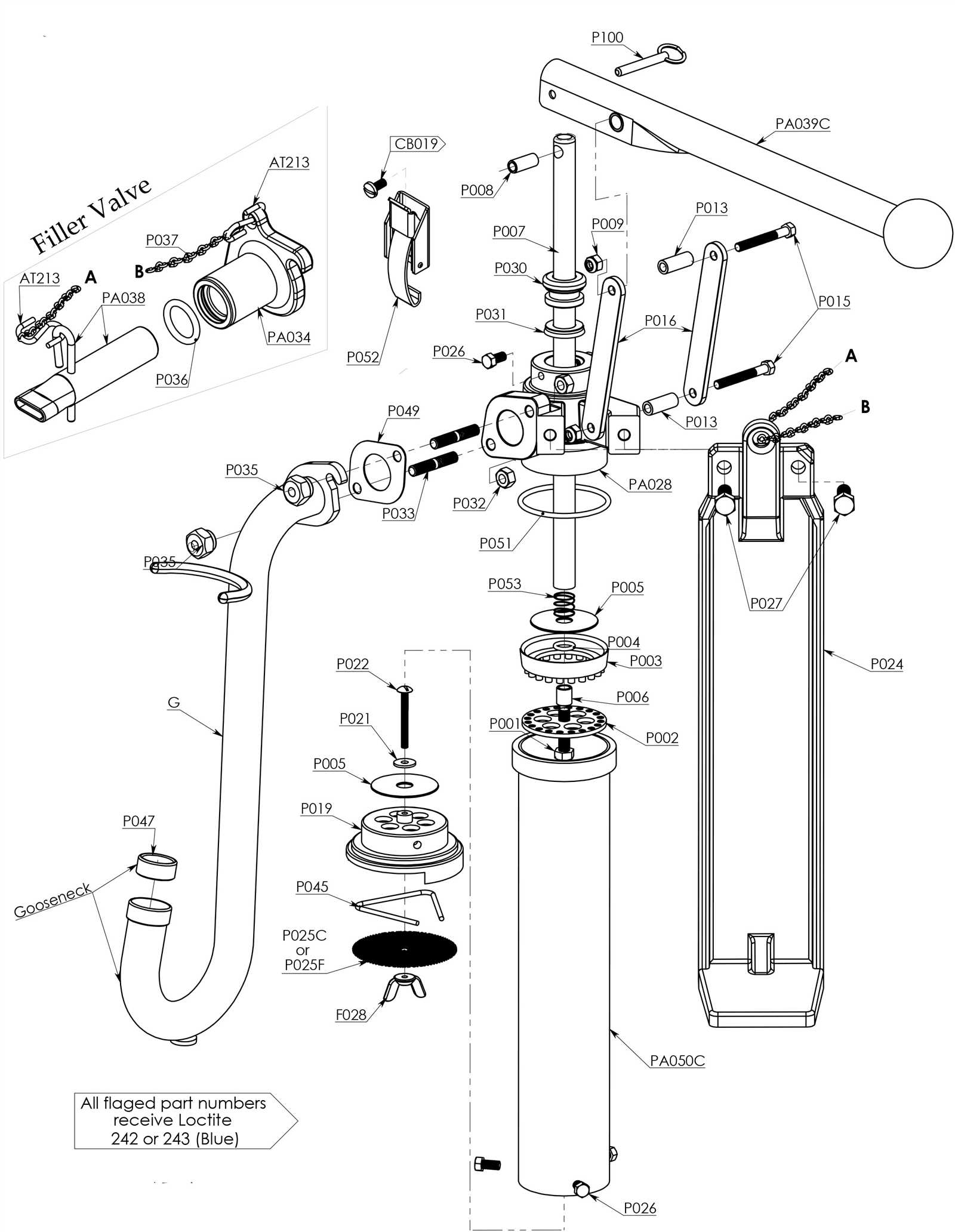
Understanding the key components of a fluid-moving system is essential for optimizing performance and ensuring reliability. Each element plays a vital role in the overall functionality, contributing to the efficiency and longevity of the entire mechanism.
- Impeller: This rotating device is responsible for transferring energy to the fluid, creating flow and pressure.
- Volute: A spiral casing that helps direct the fluid from the impeller to the discharge pipe, increasing pressure and facilitating smooth flow.
- Seal: Essential for preventing leaks, this component protects the internal elements from external contaminants.
- Motor: The driving force behind the system, providing the necessary energy for the impeller to function effectively.
- Strainer: This filtering element prevents debris from entering the system, ensuring that only clean fluid is processed.
By familiarizing yourself with these fundamental components and their specific roles, you can better understand how to maintain and troubleshoot the system effectively.
How to Read Pump Diagrams
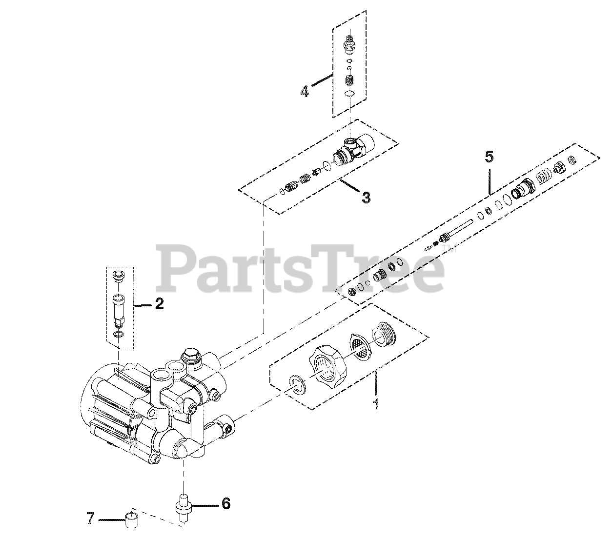
Understanding the visual representations of machinery is crucial for effective maintenance and operation. These illustrations convey essential information about the components, their relationships, and the overall functionality of the system.
To begin, familiarize yourself with the symbols used in these visuals. Each symbol typically represents a specific element, making it easier to identify what each part does. Pay attention to the accompanying legends or keys, as they provide clarity on the meanings behind the symbols.
Next, observe the flow paths indicated in the drawings. This flow direction is essential for grasping how the system operates, allowing you to anticipate the movement of fluids and understand the interactions between components. Identifying inlets and outlets will also help you comprehend the overall process.
Finally, take note of any annotations or notes present within the illustration. These can offer insights into operational parameters, maintenance tips, or safety precautions, enhancing your understanding of the entire setup. By focusing on these aspects, you’ll be equipped to effectively interpret these critical visuals.
Troubleshooting with Diagrams
Visual aids can greatly enhance the process of identifying and resolving issues within mechanical systems. Utilizing graphical representations allows technicians to quickly pinpoint potential malfunctions and develop effective solutions. This approach not only saves time but also improves overall understanding of the intricate components involved.
When faced with a malfunction, consider the following steps to guide your analysis:
- Identify the symptoms: Document the specific issues observed during operation.
- Refer to visual aids: Use graphical representations to locate the affected areas.
- Analyze connections: Examine the relationships between various components highlighted in the illustrations.
- Test individual elements: Focus on each part, utilizing diagrams to inform your checks.
- Implement solutions: Develop a plan based on your findings and execute repairs or adjustments as needed.
To effectively utilize these visual tools, keep the following tips in mind:
- Ensure clarity: Use high-quality images that clearly depict the components.
- Stay organized: Maintain a logical structure in your documentation to facilitate easy reference.
- Collaborate: Share diagrams with team members to enhance collective troubleshooting efforts.
By integrating visual representations into the troubleshooting process, technicians can streamline their efforts, leading to quicker and more effective resolutions.
Maintenance Best Practices
Effective upkeep is essential for ensuring the longevity and reliability of machinery. By implementing systematic approaches to maintenance, operators can minimize downtime and enhance overall efficiency. Regular assessments, timely repairs, and proactive measures contribute significantly to operational excellence.
Routine Inspections
Conducting frequent evaluations helps identify potential issues before they escalate. This includes checking for wear and tear, assessing lubrication levels, and ensuring all components are functioning optimally. Developing a checklist can streamline this process and ensure no critical area is overlooked.
Proper Lubrication Techniques

Utilizing the correct lubrication methods is vital for reducing friction and preventing overheating. Choosing the right lubricant based on operating conditions and manufacturer recommendations will enhance performance and extend the life of the equipment. Regularly scheduled lubrication can lead to significant improvements in efficiency and reliability.
Upgrading Your Pump System
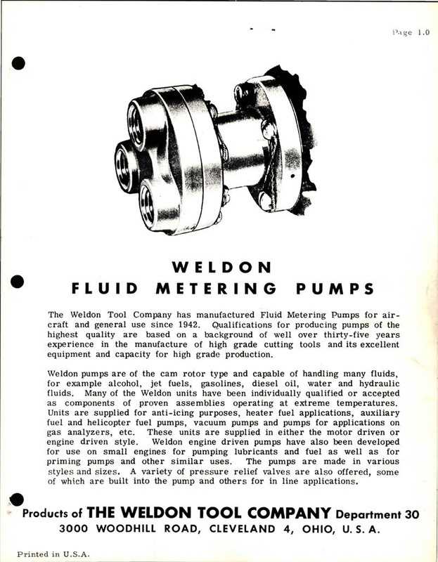
Enhancing your fluid transfer system can significantly improve efficiency and reliability. By modernizing various components, you can optimize performance and reduce operational costs. This section explores effective strategies for elevating your setup.
Assess Current Equipment: Begin by evaluating your existing machinery. Identify any outdated or underperforming elements that may be hindering overall functionality. Consider factors such as wear and tear, capacity, and energy consumption.
Implement Advanced Technology: Integrating state-of-the-art technologies can lead to remarkable improvements. Look for options like variable frequency drives or smart monitoring systems that allow for better control and automation of operations.
Upgrade Components: Replacing older components with modern alternatives can enhance performance. For instance, upgrading seals and bearings can minimize leakage and friction, while more efficient motors can significantly reduce energy use.
Regular Maintenance Schedule: Establishing a routine maintenance plan is essential for sustaining optimal performance. Regular checks and timely replacements of worn-out parts help prevent unexpected failures and extend the lifespan of your system.
Consult with Experts: Don’t hesitate to seek advice from professionals in the field. Their expertise can provide valuable insights and recommendations tailored to your specific needs, ensuring a successful upgrade.