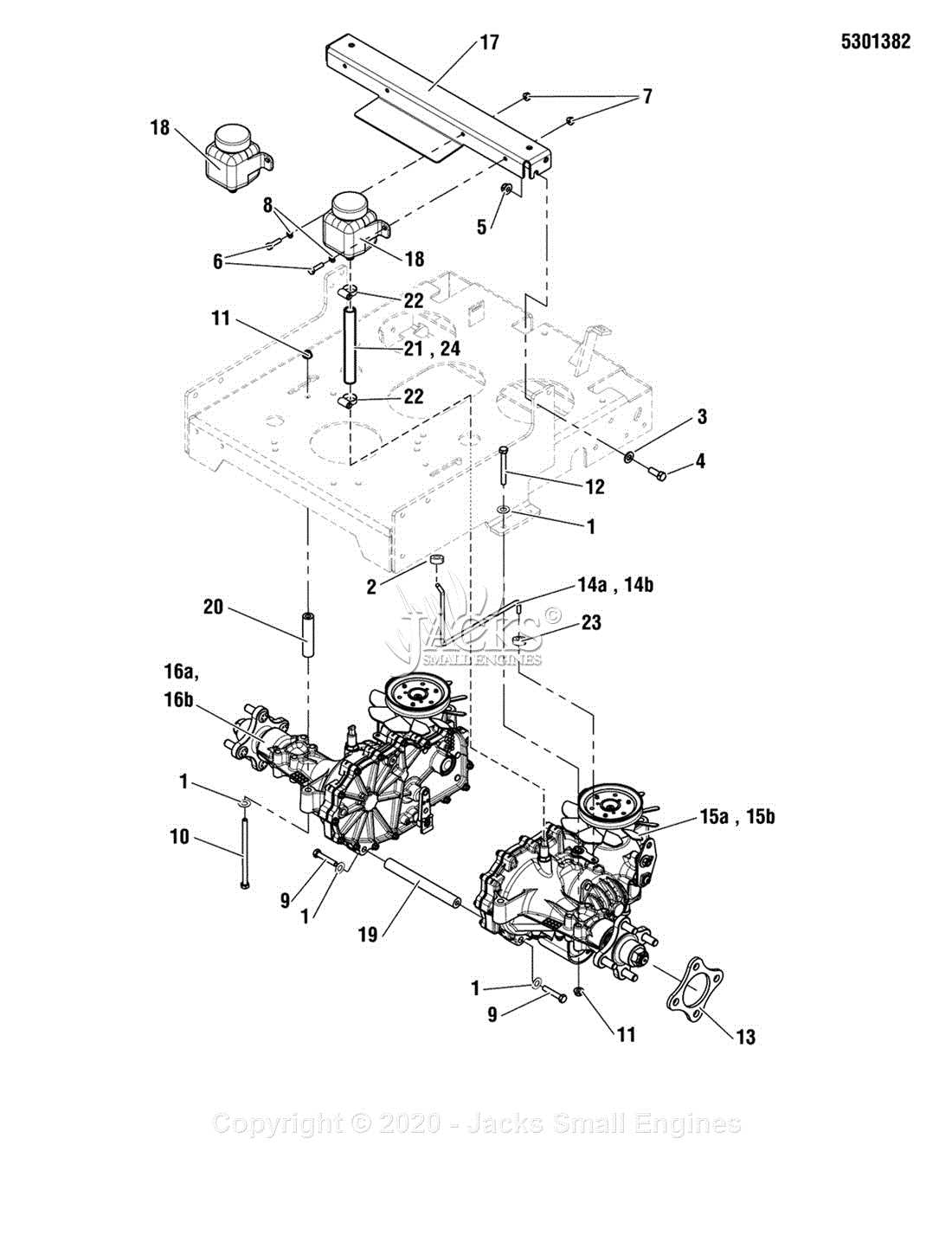
In the realm of machinery maintenance and repair, having a clear visual representation of components is essential. This approach not only enhances comprehension but also streamlines the process of identifying and addressing issues that may arise during operation. A well-organized overview serves as a valuable tool for technicians and enthusiasts alike, allowing for more efficient diagnostics and repairs.
Visual aids play a critical role in illustrating the relationships between various elements within a system. By depicting these connections, users can gain insights into how each segment functions in harmony with others. Such illustrations facilitate better troubleshooting and enhance overall understanding, ensuring that every operator can effectively manage their equipment.
When dealing with complex machinery, it is crucial to have access to detailed visual resources that simplify navigation and assembly. These resources empower individuals to maintain their systems with confidence, promoting longevity and optimal performance. Utilizing these representations can significantly reduce downtime and improve overall productivity.
Having precise representations is essential for understanding the structure and functionality of any system. These visual aids serve as a crucial reference, enabling individuals to comprehend complex relationships and components effectively.
Accurate visuals provide numerous benefits, including:
- Enhanced comprehension of intricate mechanisms.
- Improved communication among team members and stakeholders.
- Streamlined troubleshooting and maintenance processes.
- Facilitated training and onboarding of new personnel.
Inaccurate illustrations can lead to misunderstandings, which may result in errors during assembly or repair. Therefore, investing time and resources in creating and maintaining reliable representations is vital for ensuring optimal performance and safety.
Common Issues in Parts Identification
Identifying components can often present several challenges, especially when dealing with complex machinery. Users may encounter difficulties due to unclear markings, variations in design, or inadequate reference materials. Such issues can lead to confusion and incorrect replacements, affecting the overall functionality of the equipment.
Ambiguities in Component Markings

One significant challenge arises from the ambiguity in the markings found on various elements. These markings can be faded, poorly printed, or inconsistent, making it hard to determine the exact specifications needed for replacement. This can cause delays in repairs and lead to the use of incompatible items.
Inconsistencies Across Different Models
Another common issue involves inconsistencies among different models of the same type of machinery. Variations in design and specifications can make it difficult to ascertain which item is suitable for a specific model. This necessitates thorough research and verification to ensure the correct choice is made.
| Issue | Description |
|---|---|
| Unclear Markings | Faded or inconsistent markings on components can lead to misidentification. |
| Model Variations | Differences in specifications across models can complicate the identification process. |
| Insufficient Reference Materials | Limited access to clear manuals or diagrams can hinder accurate identification. |
How to Read the Diagram Effectively
Understanding the layout of components is crucial for successful maintenance and repair tasks. A clear grasp of the schematic representation allows users to identify the relationships and functions of various elements efficiently. This section provides insights on how to navigate and interpret the visual guide for optimal comprehension.
Begin by familiarizing yourself with the symbols and legends used in the representation. Each icon typically corresponds to a specific element or connection type, which can vary significantly depending on the system. Take time to study the key, as it will help decode the information presented.
| Symbol | Description |
|---|---|
| Indicates a connection point | |
| ⚙️ | Represents a mechanical component |
| Shows electrical connections | |
| Denotes a moving part or mechanism |
Once you understand the symbols, follow the lines connecting the various elements. These lines illustrate the flow and interaction between components, providing a roadmap for troubleshooting or assembly. Pay close attention to any annotations or notes that might indicate specific instructions or warnings.
Finally, practice by analyzing different representations. The more you engage with them, the more proficient you’ll become at interpreting the intricate details, leading to more effective handling of the system.
Tips for Maintenance Using Diagrams
Utilizing visual aids for upkeep can significantly enhance the efficiency and effectiveness of the maintenance process. These illustrations provide a clear representation of components, making it easier to understand how different elements interact and function together. This approach not only streamlines the repair process but also minimizes the risk of errors, ensuring that tasks are completed accurately.
Understanding Component Relationships
Grasping the connections between various elements is crucial for successful maintenance. Diagrams serve as valuable resources to illustrate how each part fits into the overall system. By studying these visuals, you can identify which components require attention and how to approach replacements or repairs.
Organizing Maintenance Tasks
Clear visual representations can help in prioritizing tasks. When you have a well-organized visual reference, you can determine the most critical areas needing maintenance. This systematic approach allows for efficient planning, ensuring that each step is carried out in a logical sequence, ultimately saving time and effort.
Resources for Additional Diagram Information
For those seeking to enhance their understanding of assembly schematics, a variety of resources are available. These platforms provide valuable insights and detailed illustrations that aid in the comprehension of complex components.
Online Resources
- Manufacturer websites often feature downloadable manuals and visual aids.
- Forums dedicated to machinery offer community-shared resources and troubleshooting advice.
- Video tutorials on platforms like YouTube can visually demonstrate the assembly process.
Printed Materials
- Technical manuals provide in-depth information and diagrams for specific models.
- Catalogs from suppliers may include reference images and specifications.
- Industry publications often contain articles that discuss best practices and maintenance tips.
Comparing Different Models’ Diagrams
Understanding the variations among various models is crucial for effective maintenance and operation. Each version may have unique configurations and components, which can significantly impact performance and functionality. Analyzing these variations helps users make informed decisions and enhances their ability to troubleshoot issues.
Key Differences in Layouts
When examining the layouts of distinct models, several factors come into play, including the arrangement of elements and the specific functions each component serves. The following table highlights notable differences:
| Feature | Model A | Model B | Model C |
|---|---|---|---|
| Element Arrangement | Linear | Compact | Open |
| Component Variability | High | Medium | Low |
| Accessibility | Easy | Moderate | Difficult |
Implications for Users
Identifying these differences can enhance user experience by tailoring maintenance strategies to each model’s specific requirements. Knowledge of component layout and functionality aids in efficient operation and prolongs the lifespan of the equipment.
FAQs About Ferris Parts Diagrams
This section addresses common inquiries regarding the schematics and components of outdoor machinery. Understanding these elements can enhance maintenance and repair processes, ensuring optimal performance and longevity of equipment.
- What is the purpose of the schematics?
These visuals provide a clear representation of the machine’s components and their relationships, making it easier to identify parts during repairs.
- How can I locate specific components?
Refer to the diagrams for numbered sections that correspond to individual components, allowing for quick identification and replacement.
- Are there any guides available for assembly?
Yes, many schematics include assembly instructions to help users understand the correct placement and orientation of each part.
- Where can I find these visuals?
Diagrams are typically available in the owner’s manual, on the manufacturer’s website, or through authorized dealers.
- What should I do if I can’t find the information I need?
If you encounter difficulties, consider contacting customer support for assistance or consulting online forums dedicated to equipment maintenance.