Small gardening machines are indispensable for maintaining a neat and tidy yard, offering the ability to tackle a variety of outdoor tasks with ease. Knowing the internal layout of these devices is crucial for proper maintenance, ensuring each element functions smoothly over time. A clear visual breakdown of individual mechanisms can greatly assist in recognizing key areas that may need attention or replacement.
For those looking to extend the life of their outdoor machinery, having a reference for the arrangement of different sections is invaluable. It provides a clearer picture of how various elements work together and where to find specific connections. This knowledge can simplify the process of troubleshooting and repair, allowing owners to address potential issues themselves, without relying on extensive technical support.
The ability to identify each segment and its role not only aids in repairs but also enhances the overall understanding of how the equipment operates. This deeper insight can lead to better upkeep and timely adjustments, ultimately ensuring the long-term performance of the device. Whether you’re a seasoned gardener or a beginner, a well-organized overview of the device’s structure is a helpful tool for keeping it in peak condition.
Understanding the Structure of MC43 Components
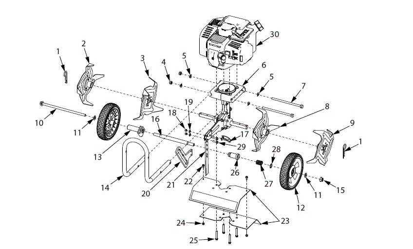
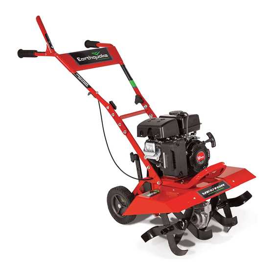
The overall assembly of this compact machine involves various interconnected elements that work together to ensure efficient performance. Each segment is designed with specific functionality, contributing to the device’s smooth operation. Exploring the different elements provides insight into how each contributes to stability, power delivery, and user control.
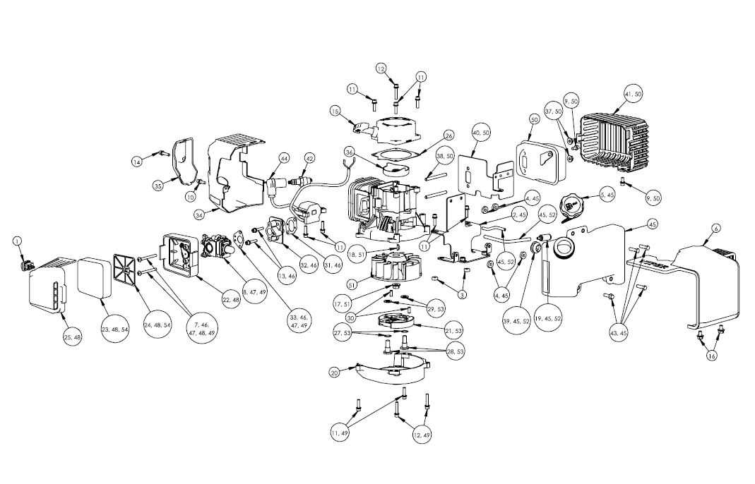
One key area of focus is the power generation unit, where energy is produced and then transferred through different channels. This section includes elements that control fuel intake, ignition, and the release of energy, ensuring consistent operation during use. Maintenance of these elements is crucial to the longevity of the unit.
The transmission section manages the flow of energy to other areas, converting raw power into controlled motion. Precision in this area ensures that the equipment maintains balance and delivers force as needed. Understanding the design of these parts can aid in troubleshooting and repair.
Additional elements like the handling controls are pivotal for user interaction, allowing smooth maneuvering and adjustments. These include grips, levers, and mechanisms that are ergonomically designed to provide ease of use and ensure safety. Proper care of these controls can significantly extend their usability and effectiveness.
Internal Mechanisms of the MC43 Model
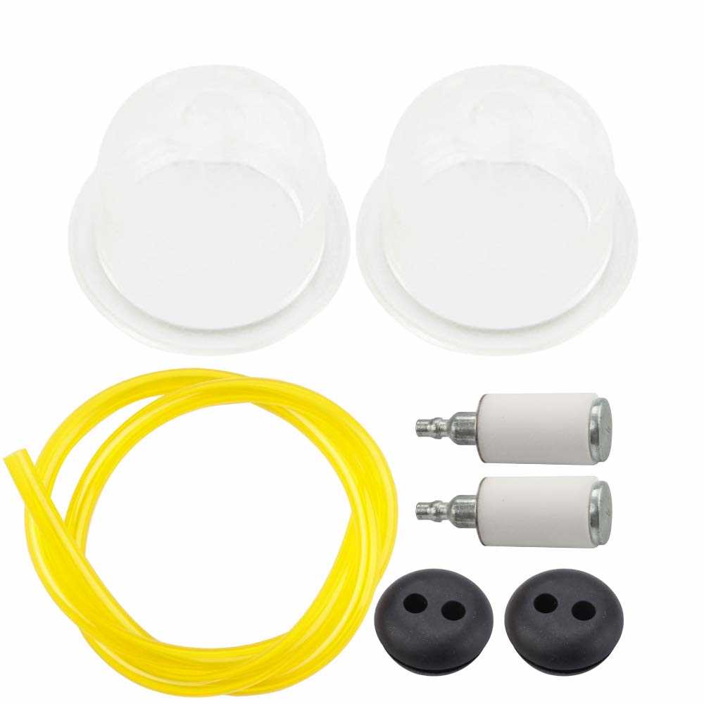
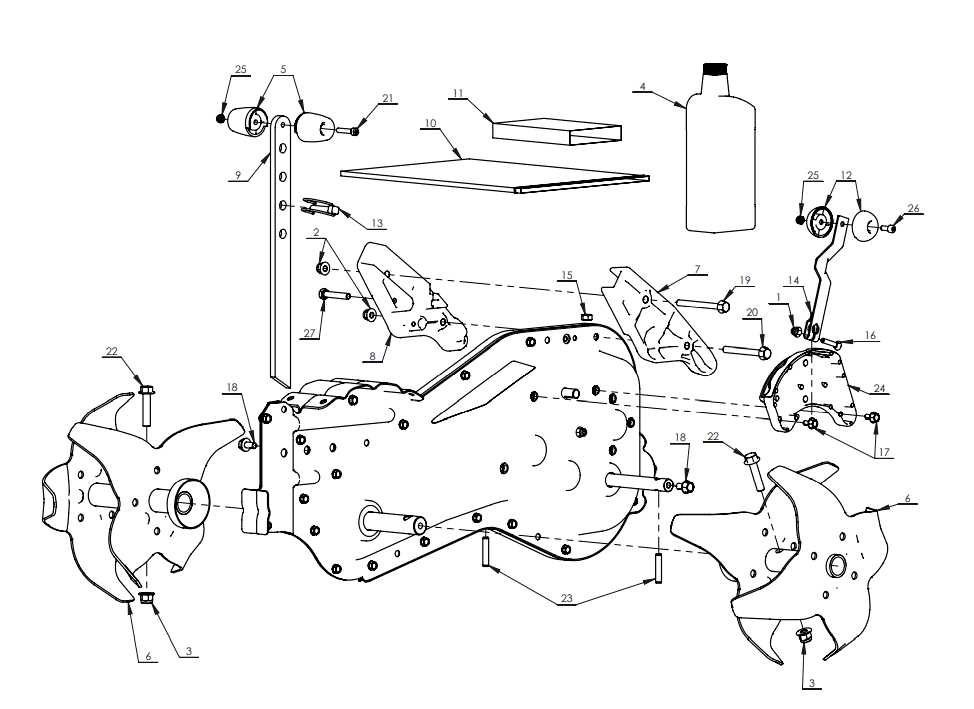
The intricate design of this model relies on a well-coordinated arrangement of components that work together to ensure efficient operation. Each element is precisely aligned to deliver consistent performance, combining mechanical precision with practical engineering.
Main Engine Structure

The core of this system includes a robust power source, connected through a series of gears and linkages. These elements translate the energy into mechanical motion, driving the device with steady force. The arrangement of these gears ensures smooth transitions, minimizing energy loss during operation. Additionally, the setup aids in reducing vibrations, enhancing the overall stability.
Transmission and Control Elements
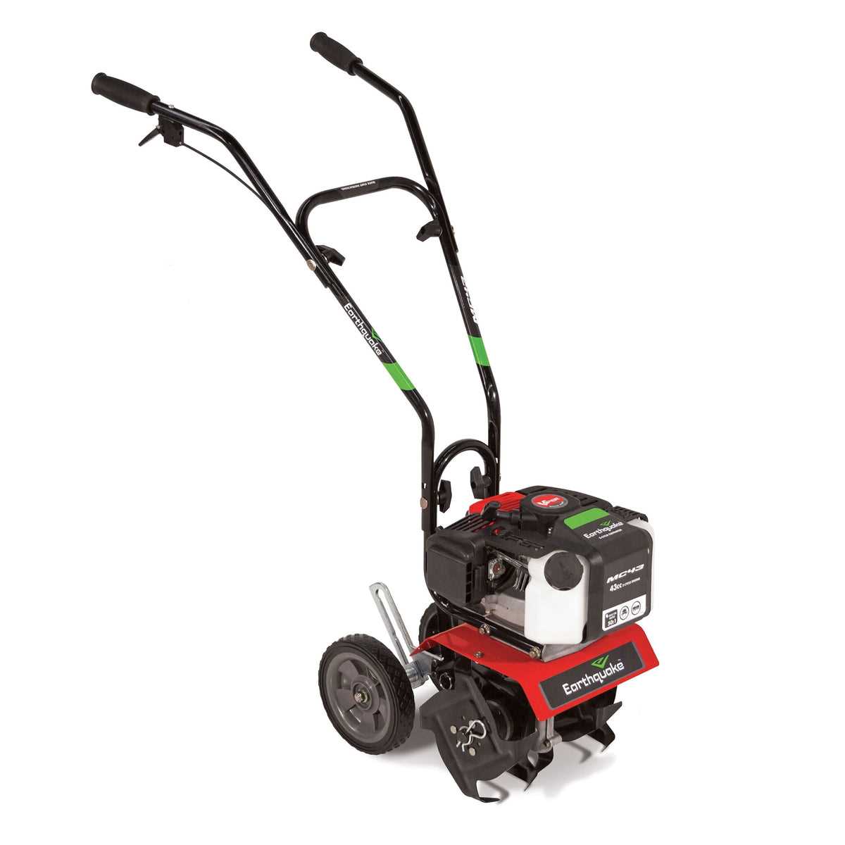
Vital control features manage the energy flow, adjusting speed and torque based on operational needs. A carefully designed transmission unit allows seamless shifts between different speeds, providing adaptability in various working conditions. This balance between power and control enables precision, ensuring that each task is completed effectively without undue strain on the system.
With these internal elements working in harmony, the model achieves a balance of power, durability, and adaptability, making it suitable for a wide range of tasks.
Key Elements in the Earthquake MC43
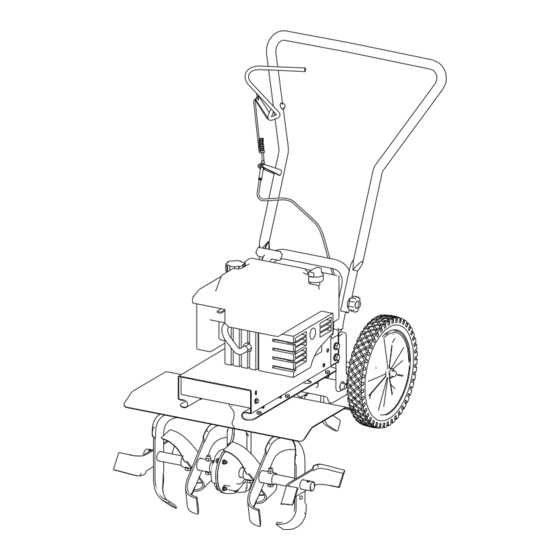
This section delves into the primary components that make up this versatile machine. Understanding each element and its function is crucial for maintaining its efficiency and ensuring smooth operation.
Engine Assembly
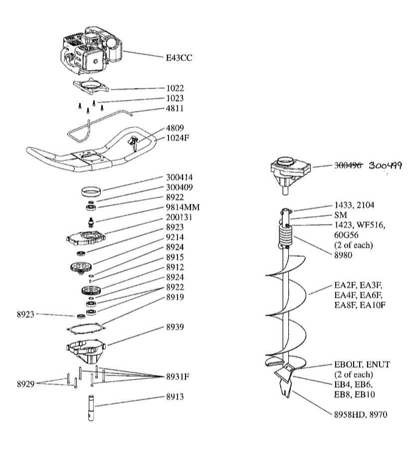
The power unit drives the entire mechanism, converting fuel into mechanical energy. Its design includes various features that work together to deliver consistent output. Proper maintenance is essential to keep this core part running smoothly.
- Fuel System: Ensures the steady flow of fuel for optimal performance.
- Cooling Mechanism: Helps in dissipating heat during extended use.
- Ignition System: Sparks the internal combustion process for starting the machine.
Transmission and Drive Mechanism

This system transfers power from the engine to the working tools, making the device capable of handling different tasks. Precision in this area determines how effectively the power is applied to the ground.
- Clutch: Regulates the connection between the power source and the working parts.
- Gearbox: Adjusts the speed and torque according to the required task.
- Drive Shaft: Transfers motion directly to the working attachments.
Assembly Guide for MC43 Parts
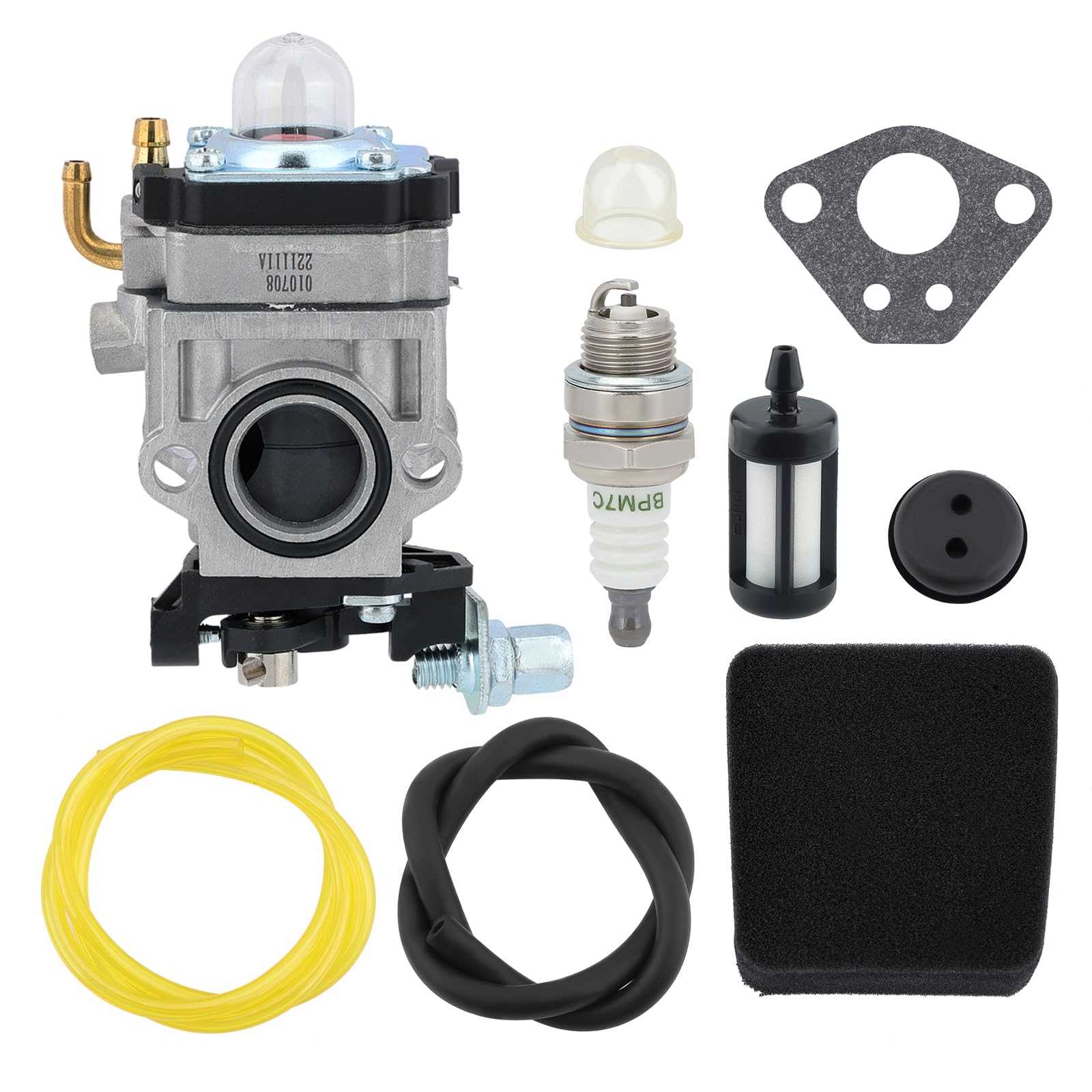
This section provides a clear and comprehensive overview of how to put together the essential components, ensuring a seamless setup process. Follow the instructions carefully to achieve proper alignment and connection of all elements.
The following table outlines the key components and their corresponding steps for an efficient build:
| Component | Step Description | ||||||||||||||||||||||||||||||||||||||||||||||||||||||
|---|---|---|---|---|---|---|---|---|---|---|---|---|---|---|---|---|---|---|---|---|---|---|---|---|---|---|---|---|---|---|---|---|---|---|---|---|---|---|---|---|---|---|---|---|---|---|---|---|---|---|---|---|---|---|---|
| Handle Assembly | Attach the upper and lower segments, securing them with provided fasteners. Ensure the alignment is straight to maintain stability during use. | ||||||||||||||||||||||||||||||||||||||||||||||||||||||
| Engine Mounting | Position the motor onto its bracket, aligning the mounting holes. Tighten screws gradually in a cross pattern for even support. | ||||||||||||||||||||||||||||||||||||||||||||||||||||||
| Control Cable Routing | Guide the control cables along the designated path, ensuring they do not twist or tangle. Secure them using clips to prevent any interference. | ||||||||||||||||||||||||||||||||||||||||||||||||||||||
| Gearbox Installation | Slide the gearbox into place, matching the grooves for a snug fit. Fasten bolts evenly to avoi
Common Issues with MC43 Components
Over time, certain elements of this machine may encounter wear or malfunctions. Understanding frequent challenges can help in diagnosing problems and prolonging the lifespan of the equipment. Below is an overview of typical concerns that users may face, accompanied by possible symptoms and their causes.
|
